US7717539B2 - Apparatus and method for coating polyimide layer - Google Patents
Apparatus and method for coating polyimide layer Download PDFInfo
- Publication number
- US7717539B2 US7717539B2 US11/645,731 US64573106A US7717539B2 US 7717539 B2 US7717539 B2 US 7717539B2 US 64573106 A US64573106 A US 64573106A US 7717539 B2 US7717539 B2 US 7717539B2
- Authority
- US
- United States
- Prior art keywords
- wiper
- cleaning
- polyimide layer
- cleaning liquid
- liquid
- Prior art date
- Legal status (The legal status is an assumption and is not a legal conclusion. Google has not performed a legal analysis and makes no representation as to the accuracy of the status listed.)
- Expired - Fee Related, expires
Links
Images


Classifications
-
- G—PHYSICS
- G02—OPTICS
- G02F—OPTICAL DEVICES OR ARRANGEMENTS FOR THE CONTROL OF LIGHT BY MODIFICATION OF THE OPTICAL PROPERTIES OF THE MEDIA OF THE ELEMENTS INVOLVED THEREIN; NON-LINEAR OPTICS; FREQUENCY-CHANGING OF LIGHT; OPTICAL LOGIC ELEMENTS; OPTICAL ANALOGUE/DIGITAL CONVERTERS
- G02F1/00—Devices or arrangements for the control of the intensity, colour, phase, polarisation or direction of light arriving from an independent light source, e.g. switching, gating or modulating; Non-linear optics
- G02F1/01—Devices or arrangements for the control of the intensity, colour, phase, polarisation or direction of light arriving from an independent light source, e.g. switching, gating or modulating; Non-linear optics for the control of the intensity, phase, polarisation or colour
- G02F1/13—Devices or arrangements for the control of the intensity, colour, phase, polarisation or direction of light arriving from an independent light source, e.g. switching, gating or modulating; Non-linear optics for the control of the intensity, phase, polarisation or colour based on liquid crystals, e.g. single liquid crystal display cells
- G02F1/133—Constructional arrangements; Operation of liquid crystal cells; Circuit arrangements
- G02F1/1333—Constructional arrangements; Manufacturing methods
- G02F1/1337—Surface-induced orientation of the liquid crystal molecules, e.g. by alignment layers
-
- B—PERFORMING OPERATIONS; TRANSPORTING
- B41—PRINTING; LINING MACHINES; TYPEWRITERS; STAMPS
- B41J—TYPEWRITERS; SELECTIVE PRINTING MECHANISMS, i.e. MECHANISMS PRINTING OTHERWISE THAN FROM A FORME; CORRECTION OF TYPOGRAPHICAL ERRORS
- B41J2/00—Typewriters or selective printing mechanisms characterised by the printing or marking process for which they are designed
- B41J2/005—Typewriters or selective printing mechanisms characterised by the printing or marking process for which they are designed characterised by bringing liquid or particles selectively into contact with a printing material
- B41J2/01—Ink jet
- B41J2/135—Nozzles
- B41J2/165—Prevention or detection of nozzle clogging, e.g. cleaning, capping or moistening for nozzles
- B41J2/16517—Cleaning of print head nozzles
- B41J2/16535—Cleaning of print head nozzles using wiping constructions
-
- B—PERFORMING OPERATIONS; TRANSPORTING
- B41—PRINTING; LINING MACHINES; TYPEWRITERS; STAMPS
- B41J—TYPEWRITERS; SELECTIVE PRINTING MECHANISMS, i.e. MECHANISMS PRINTING OTHERWISE THAN FROM A FORME; CORRECTION OF TYPOGRAPHICAL ERRORS
- B41J2/00—Typewriters or selective printing mechanisms characterised by the printing or marking process for which they are designed
- B41J2/005—Typewriters or selective printing mechanisms characterised by the printing or marking process for which they are designed characterised by bringing liquid or particles selectively into contact with a printing material
- B41J2/01—Ink jet
- B41J2/135—Nozzles
- B41J2/165—Prevention or detection of nozzle clogging, e.g. cleaning, capping or moistening for nozzles
- B41J2/16517—Cleaning of print head nozzles
- B41J2/16552—Cleaning of print head nozzles using cleaning fluids
-
- G—PHYSICS
- G02—OPTICS
- G02F—OPTICAL DEVICES OR ARRANGEMENTS FOR THE CONTROL OF LIGHT BY MODIFICATION OF THE OPTICAL PROPERTIES OF THE MEDIA OF THE ELEMENTS INVOLVED THEREIN; NON-LINEAR OPTICS; FREQUENCY-CHANGING OF LIGHT; OPTICAL LOGIC ELEMENTS; OPTICAL ANALOGUE/DIGITAL CONVERTERS
- G02F1/00—Devices or arrangements for the control of the intensity, colour, phase, polarisation or direction of light arriving from an independent light source, e.g. switching, gating or modulating; Non-linear optics
- G02F1/01—Devices or arrangements for the control of the intensity, colour, phase, polarisation or direction of light arriving from an independent light source, e.g. switching, gating or modulating; Non-linear optics for the control of the intensity, phase, polarisation or colour
- G02F1/13—Devices or arrangements for the control of the intensity, colour, phase, polarisation or direction of light arriving from an independent light source, e.g. switching, gating or modulating; Non-linear optics for the control of the intensity, phase, polarisation or colour based on liquid crystals, e.g. single liquid crystal display cells
Definitions
- Embodiments of the invention relates to coating, and more particularly, to an apparatus and method for coating a polyimide layer.
- a liquid crystal display (LCD) device is an apparatus for displaying a desired image by adjusting quantity of light reaching a color filter substrate. The adjustment of the quantity of light is accomplished by changing intermolecular orientation of liquid crystal molecules interposed between a transparent insulating substrate serving as the color filter substrate and an array substrate.
- LCD liquid crystal display
- TFT LCD thin film transistor liquid crystal display
- an LCD device includes an LCD panel for displaying an image and a driver for driving the LCD panel by applying driving signals to the LCD panel.
- the LCD panel includes a color filter substrate and an array substrate bonded to each other with a predetermined gap therebetween.
- a layer of liquid crystal molecules is in the gap between the color filter substrate and the array substrate.
- the color filter substrate and the array substrate of the LCD panel are manufactured through a plurality of masking processes.
- Polyimide layers are formed on respective substrates after finishing the masking processes and before the substrates are bonded to each other.
- the polyimide layers are used as alignment films to arrange the liquid crystal molecules in a predetermined direction.
- the polyimide layers can be coated on the substrates through a variety of methods, such as a spin-coating method, a spray-coating method, and an inkjet-coating method.
- a spin-coating method a spray-coating method
- an inkjet-coating method a coating method that is the quickest and easiest to apply because of the use of an inkjet coating apparatus.
- a plurality of inkjet heads are used in an inkjet coating apparatus to jet polyimide liquid onto the substrates.
- FIG. 1A and FIG. 1B are schematic views illustrating an accumulation problem in an apparatus for coating a polyimide layer according to the related art. More specifically, FIG. 1A and FIG. 1B are schematic views illustrating the surface flatness of the inkjet head 10 before and after jetting polyimide liquid onto the substrates in the inkjet-coating method according to the related art.
- the inkjet head 10 moves in a predetermined direction above a print table on which a target substrate is placed while jetting polyimide liquid onto the target substrate, thereby coating a polyimide layer onto the substrate. As shown in FIG.
- polyimide liquid when the jetting surface of the inkjet head 10 is clean and does not have any residue thereon, polyimide liquid can be jetted uniformly so that a polyimide layer having uniform thickness can be formed on the substrate.
- polyimide liquid residue can accumulate on the jetting surface A 1 of the inkjet head 10 even after only one inkjet coating process.
- a non-uniform polyimide layer may be coated on a substrate or, in extreme cases, no polyimide layer is coated on a substrate.
- the non-uniform polyimide layer can include pinhole faults and/or line blemishes. Even if the jetting surface of the inkjet head is cleaned using a cleaning bar, polyimide residue may still remain on the inkjet head.
- embodiments of the invention is directed to an apparatus and method for coating a polyimide layer that substantially obviates one or more of the problems due to limitations and disadvantages of the related art.
- An object of embodiments of the invention is to provide an apparatus and method for coating a polyimide layer that includes the capability of effectively removing polyimide residue from the jetting surface of an inkjet head.
- Another object of embodiments of the invention is to provide an apparatus and method for coating a polyimide layer that prevents pinhole faults and line blemishes from occurring in the polyimide layer.
- an apparatus for coating polyimide layer includes a print table for affixing a substrate thereon, an inkjet head installed over the print table and having a jetting surface with a plurality of nozzles for jetting polyimide liquid onto the substrate, a polyimide liquid supply tank for receiving a polyimide liquid therein, a cleaning liquid supply tank for receiving cleaning liquid, a wiper cleaning bar adjacent to the cleaning liquid supply tank, and a wiper movable from one side of the jetting surface to an other side of the jetting surface while the wiper contacts the jetting surface of the inkjet head, and rotatable to dip the wiper into the cleaning liquid and then contact the wiper cleaning bar so as to remove cleaning liquid from the wiper.
- method for coating polyimide layer that includes placing a substrate on a print table, loading polyimide liquid into a polyimide liquid supply tank, loading a cleaning liquid vessel filled with cleaning liquid into a cleaning liquid supply tank, jetting the polyimide liquid onto the substrate through a plurality of nozzles provided in the jetting surface of the inkjet head after the polyimide liquid is supplied to the inkjet head installed over the print table, wiping off the jetting surface with a wiper, dipping the wiper into the cleaning liquid, and removing the cleaning liquid remaining on the wiper with a wiper cleaning bar.
- a method for coating polyimide layer includes wiping off a jetting surface of an inkjet head after polyimide liquid is jetted from the inkjet head with a wiper, dipping the wiper into the cleaning liquid, rotating the wiper into a first direction so as to dip the wiper into the cleaning liquid, and rotating the wiper further in the first direction such that the wiper contacts the wiper cleaning bar.
- FIG. 1A and FIG. 1B are schematic views illustrating an accumulation problem in an apparatus for coating a polyimide layer according to the related art
- FIG. 2 is a schematic diagram illustrating an apparatus for coating a polyimide layer according to an embodiment of the invention
- FIG. 3A through FIG. 3C are schematic views for showing operational movement of a wiper with respect to a wiper cleaning bar
- FIG. 4 is a flow chart showing a method of coating a polyimide layer according to another embodiment of the invention.
- FIG. 5 shows a process for wiping an inkjet head in accordance with the process step of FIG. 4 ;
- FIGS. 6A-6C shows a process for cleaning a wiper in accordance with the process steps of FIG. 4 .
- FIG. 2 illustrates constitution of an apparatus for coating a polyimide layer according to an embodiment of the invention.
- the apparatus for coating a polyimide layer according to an embodiment of the invention includes a print table 100 , an inkjet head 110 , a polyimide liquid supply tank 102 , and a wiper 130 .
- the polyimide layer coating apparatus has the print table 100 on which the substrate 120 to be coated with a polyimide layer is placed and fixed.
- the substrate 120 can either be a color filter substrate or a thin film transistor array substrate of an LCD device.
- a plurality of inkjet heads 110 are arranged in parallel with each other over the substrate 120 , and each inkjet head 110 is connected to the polyimide liquid supply tank 102 .
- the polyimide liquid supply tank 102 receives polyimide liquid from a pressure tank 101 , and supplies the polyimide liquid to the inkjet head 110 at a predetermined constant pressure and flow rate.
- Polyimide liquid has the advantage of being heat resistant, chemically stable and high reliability.
- a gas connection pipe provides nitrogen (N 2 ) to the pressure tank 101 .
- a polyimide liquid recovery connection pipe provides polyimide liquid recovered from the inkjet head to the pressure tank 101 .
- a polyimide supply connection pipe through which polyimide liquid is provided to the polyimide supply tank 102 through a filter is connected to the pressure tank 101 .
- a back pressure supply connection pipe for providing back pressure to a cleaning liquid supply tank 103 is also connected to the pressure tank 101 . Further, each connection pipe is provided with a valve for controlling amount of the content passing through the connection pipes and the pressure in the connection pipes.
- a jetting surface of each inkjet head 110 which faces the substrate 120 , is provided with a plurality of nozzles 111 for jetting the polyimide liquid therethrough.
- the inkjet head 110 scans over the substrate 120 while jetting the polyimide liquid onto the substrate 120 , thereby forming a polyimide layer on the substrate 120 .
- the jetting surface of the inkjet head 110 is wet with the polyimide liquid.
- the polyimide liquid remaining on the jetting surface of the inkjet head 110 is then removed through a wiping method. Accordingly, the jetting surface of the inkjet head is maintained in a state such that polyimide liquid can be jetted uniformly.
- the wiper 130 is installed in a manner such that it can move along a moving shaft 131 while the wiper 130 maintains contact with the jetting surfaces of the inkjet 110 , so that the wiper 130 can perform a wiping operation. After finishing the wiping operation, the wiper 130 rotates 180 degrees from a wiping position so as to be dipped into a cleaning liquid in the cleaning liquid supply tank 103 , and then further rotates another 180 degrees to go back to the wiping position. While returning to the wiping position, the wiper 130 comes into contact with the wiper cleaning bar 140 .
- any remaining polyimide and/or cleaning liquid on the wiper 130 is removed as the wiper 130 moves past the wiper cleaning bar 140 . Further, the wiper 130 can be dipped and wiped again before another wiping operation.
- the cleaning liquid supply tank 103 receives a cleaning liquid vessel filled with cleaning liquid and supplies the cleaning liquid when cleaning the wiper 130 .
- the cleaning liquid can be an imide-based polar solvent N-Methyl pyrrolidone (NMP).
- the wiper cleaning bar 140 is installed in such a manner that the wiper cleaning bar 140 can come into contact with the surface of the wiper 130 after the wiper 130 is dipped into the cleaning liquid so that the wiper cleaning bar 140 removes cleaning liquid and any remaining polyimide from the surface of the wiper 130 .
- the polyimide liquid supply tank 102 and the cleaning liquid supply tank 103 can be structured such that they respectively receive the polyimide liquid in a polyimide liquid filled vessel and a cleaning liquid filled vessel, which expel their contents in response to an external gas pressure. Accordingly, the polyimide liquid supply tank 102 and the cleaning liquid supply tank 103 can be a single tank that receives both the polyimide liquid vessel and the cleaning liquid vessel. In other words, the polyimide liquid vessel and the cleaning liquid vessel share a single tank.
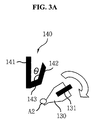
- FIG. 3A through FIG. 3C are schematic views for showing operational movement of a wiper with respect to a wiper cleaning bar.
- FIG. 3A through FIG. 3C illustrate the process sequence in which the wiper 130 is cleaned using the cleaning liquid, and then residue on the wiper 130 is removed as the wiper 130 rotates on a moving shaft 131 so that the wiper 130 contacts the wiper cleaning bar 140 .
- the cleaning bar 140 includes a vertical support 141 affixed to the support 104 , a first cleaning structure 143 attached to the vertical support 141 and having an inclined surface facing the wiper 130 , and a second cleaning structure 143 attached to the first cleaning structure 143 and having another inclined surface facing the wiper 130 .
- the wiper 130 When the wiper 130 is rotated in a first direction from an initial position, the wiper 130 is dipped into the cleaning liquid. When the wiper 130 is then further rotated in the first direction, the wiper 130 contacts the wiper cleaning bar 140 as the wiper 130 is returned to its initial position.
- the first rotation in which the wiper 130 rotates to a cleaning position so that the wiper 130 dipped into the cleaning liquid is done in a clockwise direction when the upper surface of the wiper 130 goes from contacting the jetting surface of the inkjet head 110 to being dipped into cleaning liquid.
- the wiper 130 contacts the wiper cleaning bar 140 and then the upper surface of the wiper 130 contacts the jetting surface of the inkjet head 110 .
- the wiper cleaning bar 140 is configured so as to minimize a frictional force between the wiper 130 and the wiper cleaning bar 140 when the wiper 130 comes into contact with the wiper cleaning bar 140 by rotation of the wiper 130 .
- the first cleaning structure 142 has an angle ⁇ in a range of 90 to 140 degrees with respect to the second cleaning structure 143 .
- the wiper cleaning bar 140 may be made of stainless steel, aluminum, carbon graphite, carbon steel, cast iron, Ethylene Propylene Dien Rubber (EPDM), Polytrafluore Ethylene (PTEE) or Fluorocarbon (FKM).
- FIG. 4 is a flow chart illustrating the method for coating a polyimide layer according to another embodiment of the invention
- FIG. 5 shows a process for wiping an inkjet head in accordance with the process step of FIG. 4
- FIGS. 6A-6C shows a process for cleaning a wiper in accordance with the process steps of FIG. 4 .
- a substrate 120 is positioned and affixed to the print table 100 .
- the substrate 120 may be a thin film transistor array substrate or a color filter substrate of an LCD device.
- a polyimide liquid vessel filled with polyimide liquid is loaded into the polyimide liquid supply tank 102 , as described in steps S 110 and S 120 of FIG. 4 .
- the polyimide liquid is supplied to the inkjet head 110 installed over the print table 100 , and then jetted on the substrate 120 through the nozzles 111 provided on the jetting surface of the inkjet 110 .
- the wiper 130 moves to contact the jetting surface of the inkjet 110 and wipes off the nozzles 111 of the inkjet head 110 in a wiping operation, as described in step S 130 of FIG. 4 .
- polyimide liquid residue A 1 may remain on the wiper 130 .
- a cleaning liquid vessel filled with cleaning liquid is loaded into the cleaning liquid supply tank, and then the wiper 130 rotates from an initial position, as shown in FIG. 6A , to dip into the cleaning liquid so that the wiper 130 is cleaned.
- the cleaning liquid can be N-Methyl pyrrolidone imide-based polar solvent to remove both cured and un-cured polyimide liquid.
- the wiper 130 rotates so as to come into contact with the wiper cleaning bar 140 so that polyimide liquid residue and/or any cleaning liquid remaining on the wiper 130 can be removed and then the wiper 130 further rotates to return to the initial position.
- FIG. 6B and FIG. 6C illustrate respective conditions of the wiper 130 before and after performing the step S 160 , as described in FIG. 4 .
- the cleaning liquid and the polyimide liquid residue A 2 remaining on the wiper 130 are removed when the wiper 130 comes into contact with the wiper cleaning bar 140 , so that a clean wiper 130 can be subsequently used to wipe off the inkjet head 110 .
- the wiper 130 rotates in a first direction from an initial position to dip into then cleaning liquid, and then rotates further in the first direction back to the initial position after coming into contact with the wiper cleaning bar 140 to remove cleaning liquid from the wiper 30 .
- the inkjet head 110 of the polyimide layer coating apparatus can then be wiped off with a clean wiper 130 because the wiper cleaning bar 140 keeps the wiper 130 clean such that polyimide liquid residue remaining on the inkjet head 110 can be effectively removed.
- the polyimide layer coating apparatus and method according to embodiments of the invention can reduce pinhole faults and line blemishes by effectively removing polyimide liquid residue on the surface of inkjet when forming a polyimide layer through an inkjet coating method.
Landscapes
- Physics & Mathematics (AREA)
- Nonlinear Science (AREA)
- Chemical & Material Sciences (AREA)
- Crystallography & Structural Chemistry (AREA)
- General Physics & Mathematics (AREA)
- Optics & Photonics (AREA)
- Spectroscopy & Molecular Physics (AREA)
- Mathematical Physics (AREA)
- Application Of Or Painting With Fluid Materials (AREA)
- Coating Apparatus (AREA)
- Liquid Crystal (AREA)
- Optical Filters (AREA)
Abstract
Description
Claims (20)
Applications Claiming Priority (2)
| Application Number | Priority Date | Filing Date | Title |
|---|---|---|---|
| KR1020060028389A KR101184069B1 (en) | 2006-03-29 | 2006-03-29 | Apparatus and method for coating polyimide layer on the glass |
| KR10-2006-0028389 | 2006-03-29 |
Publications (2)
| Publication Number | Publication Date |
|---|---|
| US20070229579A1 US20070229579A1 (en) | 2007-10-04 |
| US7717539B2 true US7717539B2 (en) | 2010-05-18 |
Family
ID=38558229
Family Applications (1)
| Application Number | Title | Priority Date | Filing Date |
|---|---|---|---|
| US11/645,731 Expired - Fee Related US7717539B2 (en) | 2006-03-29 | 2006-12-27 | Apparatus and method for coating polyimide layer |
Country Status (4)
| Country | Link |
|---|---|
| US (1) | US7717539B2 (en) |
| JP (1) | JP4620036B2 (en) |
| KR (1) | KR101184069B1 (en) |
| CN (1) | CN101045613B (en) |
Cited By (1)
| Publication number | Priority date | Publication date | Assignee | Title |
|---|---|---|---|---|
| US20180339465A1 (en) * | 2017-05-23 | 2018-11-29 | Xyzprinting, Inc. | Coloring nozzle cleaning assembly |
Families Citing this family (7)
| Publication number | Priority date | Publication date | Assignee | Title |
|---|---|---|---|---|
| JP4257367B2 (en) * | 2007-04-27 | 2009-04-22 | シャープ株式会社 | Cleaning device for liquid material discharge device |
| US9144134B2 (en) | 2012-08-24 | 2015-09-22 | Shenzhen China Star Optoelectronics Technology Co., Ltd | Method for coating polyimide on liquid crystal display panel |
| CN102826765B (en) * | 2012-08-24 | 2015-10-07 | 深圳市华星光电技术有限公司 | The polyimide coating method of display panels |
| CN102921663B (en) * | 2012-11-22 | 2015-07-29 | 深圳市华星光电技术有限公司 | A kind of clean method of alignment film printing machine shower nozzle and device |
| CN109016845B (en) * | 2018-08-07 | 2019-11-15 | 杭州三晶工艺塑料有限公司 | A kind of printed glass production process |
| KR102768797B1 (en) * | 2019-03-11 | 2025-02-19 | 삼성디스플레이 주식회사 | Inkjet head cleaning apparatus, inkjet head cleaning method and substrate treating method using the same |
| KR102694033B1 (en) * | 2022-03-03 | 2024-08-09 | 에이치비솔루션㈜ | Profile feedback patterning system for reducing stitch mura of multi head inkjet printing |
Citations (12)
| Publication number | Priority date | Publication date | Assignee | Title |
|---|---|---|---|---|
| JPH0789092A (en) | 1993-09-22 | 1995-04-04 | Toray Ind Inc | Cleaning method and water-based washing liquid of ink jet recorder |
| JPH08150710A (en) | 1994-11-30 | 1996-06-11 | Canon Inc | Liquid ejecting apparatus and printing system using the same |
| US5607732A (en) * | 1994-09-30 | 1997-03-04 | Nissan Chemical Industries, Ltd. | Treating method for aligning liquid crystal molecules and liquid crystal display device |
| JPH1076203A (en) | 1996-08-30 | 1998-03-24 | Tokyo Electron Ltd | Liquid treatment method and apparatus |
| JPH11123832A (en) | 1997-10-22 | 1999-05-11 | Canon Inc | Inkjet printer |
| US6164754A (en) * | 1996-11-06 | 2000-12-26 | Canon Kabushiki Kaisha | Liquid discharging recording apparatus with elastic head cleaning member |
| JP2002254663A (en) | 2001-02-27 | 2002-09-11 | Seiko Epson Corp | Cleaning device for ink discharge unit, ink discharge device having this cleaning device |
| JP2003001835A (en) | 2001-04-20 | 2003-01-08 | Seiko Epson Corp | Maintenance device, maintenance method, and inkjet printer using the same |
| JP2003136013A (en) | 2001-11-02 | 2003-05-13 | Seiko Epson Corp | Method for manufacturing film laminate, method for manufacturing electro-optical panel, method for manufacturing liquid crystal panel, and method for manufacturing electronic equipment |
| US6726304B2 (en) * | 1998-10-09 | 2004-04-27 | Eastman Kodak Company | Cleaning and repairing fluid for printhead cleaning |
| US6827619B2 (en) * | 1998-12-25 | 2004-12-07 | Canon Kabushiki Kaisha | Electron emitting device, electron source, image forming apparatus and producing methods of them |
| US20050122351A1 (en) * | 2003-10-28 | 2005-06-09 | Semiconductor Energy Laboratory Co., Ltd | Liquid droplet ejection system and control program of ejection condition of compositions |
Family Cites Families (3)
| Publication number | Priority date | Publication date | Assignee | Title |
|---|---|---|---|---|
| KR101060421B1 (en) * | 2003-04-03 | 2011-08-29 | 엘지디스플레이 주식회사 | Alignment film forming apparatus of liquid crystal display device |
| JP3772873B2 (en) * | 2003-10-28 | 2006-05-10 | セイコーエプソン株式会社 | Film formation method |
| JP2006075687A (en) * | 2004-09-08 | 2006-03-23 | Seiko Epson Corp | Droplet discharge device, head cleaning method, electro-optical device manufacturing method, electro-optical device, and electronic apparatus |
-
2006
- 2006-03-29 KR KR1020060028389A patent/KR101184069B1/en not_active Expired - Fee Related
- 2006-11-29 CN CN200610160657XA patent/CN101045613B/en not_active Expired - Fee Related
- 2006-12-15 JP JP2006338486A patent/JP4620036B2/en not_active Expired - Fee Related
- 2006-12-27 US US11/645,731 patent/US7717539B2/en not_active Expired - Fee Related
Patent Citations (13)
| Publication number | Priority date | Publication date | Assignee | Title |
|---|---|---|---|---|
| JPH0789092A (en) | 1993-09-22 | 1995-04-04 | Toray Ind Inc | Cleaning method and water-based washing liquid of ink jet recorder |
| US5607732A (en) * | 1994-09-30 | 1997-03-04 | Nissan Chemical Industries, Ltd. | Treating method for aligning liquid crystal molecules and liquid crystal display device |
| JPH08150710A (en) | 1994-11-30 | 1996-06-11 | Canon Inc | Liquid ejecting apparatus and printing system using the same |
| US5912054A (en) | 1996-08-30 | 1999-06-15 | Tokyo Electron Limited | Coating method and apparatus |
| JPH1076203A (en) | 1996-08-30 | 1998-03-24 | Tokyo Electron Ltd | Liquid treatment method and apparatus |
| US6164754A (en) * | 1996-11-06 | 2000-12-26 | Canon Kabushiki Kaisha | Liquid discharging recording apparatus with elastic head cleaning member |
| JPH11123832A (en) | 1997-10-22 | 1999-05-11 | Canon Inc | Inkjet printer |
| US6726304B2 (en) * | 1998-10-09 | 2004-04-27 | Eastman Kodak Company | Cleaning and repairing fluid for printhead cleaning |
| US6827619B2 (en) * | 1998-12-25 | 2004-12-07 | Canon Kabushiki Kaisha | Electron emitting device, electron source, image forming apparatus and producing methods of them |
| JP2002254663A (en) | 2001-02-27 | 2002-09-11 | Seiko Epson Corp | Cleaning device for ink discharge unit, ink discharge device having this cleaning device |
| JP2003001835A (en) | 2001-04-20 | 2003-01-08 | Seiko Epson Corp | Maintenance device, maintenance method, and inkjet printer using the same |
| JP2003136013A (en) | 2001-11-02 | 2003-05-13 | Seiko Epson Corp | Method for manufacturing film laminate, method for manufacturing electro-optical panel, method for manufacturing liquid crystal panel, and method for manufacturing electronic equipment |
| US20050122351A1 (en) * | 2003-10-28 | 2005-06-09 | Semiconductor Energy Laboratory Co., Ltd | Liquid droplet ejection system and control program of ejection condition of compositions |
Non-Patent Citations (1)
| Title |
|---|
| Office Action issued Dec. 7, 2009 in corresponding Japanese Application No. 2006-338486. |
Cited By (2)
| Publication number | Priority date | Publication date | Assignee | Title |
|---|---|---|---|---|
| US20180339465A1 (en) * | 2017-05-23 | 2018-11-29 | Xyzprinting, Inc. | Coloring nozzle cleaning assembly |
| US10821734B2 (en) * | 2017-05-23 | 2020-11-03 | Xyzprinting, Inc. | Coloring nozzle cleaning assembly |
Also Published As
| Publication number | Publication date |
|---|---|
| US20070229579A1 (en) | 2007-10-04 |
| JP2007260662A (en) | 2007-10-11 |
| KR20070097741A (en) | 2007-10-05 |
| CN101045613A (en) | 2007-10-03 |
| KR101184069B1 (en) | 2012-09-19 |
| CN101045613B (en) | 2011-09-14 |
| JP4620036B2 (en) | 2011-01-26 |
Similar Documents
| Publication | Publication Date | Title |
|---|---|---|
| US8354142B2 (en) | Method for coating polyimide layer using inkjet device | |
| US7987782B2 (en) | Printing apparatus for liquid crystal display device and pattern forming method using the same | |
| US7717539B2 (en) | Apparatus and method for coating polyimide layer | |
| US20070263026A1 (en) | Methods and apparatus for maintaining inkjet print heads using parking structures | |
| US20070252863A1 (en) | Methods and apparatus for maintaining inkjet print heads using parking structures with spray mechanisms | |
| JP3073493B1 (en) | Method for forming alignment film of liquid crystal display element | |
| US7980196B2 (en) | Apparatus and method for coating polyimide layer | |
| US20070256709A1 (en) | Methods and apparatus for operating an inkjet printing system | |
| US20050079644A1 (en) | Method for manufacturing electro-optical panel | |
| JPH09166783A (en) | Method and apparatus for forming alignment film of liquid crystal display element | |
| US8662621B2 (en) | Droplet jetting applicator and method of manufacturing coated body | |
| KR20040089493A (en) | Liquid-applying apparatus and method of cleaning a head | |
| JP3994915B2 (en) | Electro-optical panel manufacturing method, electro-optical panel manufacturing program, electro-optical panel manufacturing apparatus, and electronic apparatus manufacturing method | |
| US20070231497A1 (en) | Apparatus and method for coating polyimide layer | |
| US7611759B2 (en) | Polarizer, method of manufacturing the polarizer, apparatus for manufacturing the polarizer, and display apparatus having the polarizer | |
| WO2010004990A1 (en) | Cleaning apparatus, printing apparatus and cleaning method | |
| KR20080082077A (en) | Alignment film printing device | |
| KR101331806B1 (en) | Apparatus and method for forming alignment film of liquid crystal display device | |
| KR101130208B1 (en) | Treating fluid dispensing method | |
| JP2006320839A (en) | Alignment film droplet ejection method and droplet ejection apparatus | |
| JP2005118633A (en) | Film forming method, film forming apparatus, liquid crystal device, electronic device |
Legal Events
| Date | Code | Title | Description |
|---|---|---|---|
| AS | Assignment |
Owner name: LG.PHILIPS LCD CO., LTD., KOREA, REPUBLIC OF Free format text: ASSIGNMENT OF ASSIGNORS INTEREST;ASSIGNOR:SEO, HWANG UN;REEL/FRAME:018750/0319 Effective date: 20061226 Owner name: LG.PHILIPS LCD CO., LTD.,KOREA, REPUBLIC OF Free format text: ASSIGNMENT OF ASSIGNORS INTEREST;ASSIGNOR:SEO, HWANG UN;REEL/FRAME:018750/0319 Effective date: 20061226 |
|
| AS | Assignment |
Owner name: LG DISPLAY CO., LTD., KOREA, REPUBLIC OF Free format text: CHANGE OF NAME;ASSIGNOR:LG.PHILIPS LCD CO., LTD.;REEL/FRAME:021772/0701 Effective date: 20080304 Owner name: LG DISPLAY CO., LTD.,KOREA, REPUBLIC OF Free format text: CHANGE OF NAME;ASSIGNOR:LG.PHILIPS LCD CO., LTD.;REEL/FRAME:021772/0701 Effective date: 20080304 |
|
| FEPP | Fee payment procedure |
Free format text: PAYOR NUMBER ASSIGNED (ORIGINAL EVENT CODE: ASPN); ENTITY STATUS OF PATENT OWNER: LARGE ENTITY |
|
| REMI | Maintenance fee reminder mailed | ||
| LAPS | Lapse for failure to pay maintenance fees | ||
| STCH | Information on status: patent discontinuation |
Free format text: PATENT EXPIRED DUE TO NONPAYMENT OF MAINTENANCE FEES UNDER 37 CFR 1.362 |
|
| STCH | Information on status: patent discontinuation |
Free format text: PATENT EXPIRED DUE TO NONPAYMENT OF MAINTENANCE FEES UNDER 37 CFR 1.362 |
|
| FP | Lapsed due to failure to pay maintenance fee |
Effective date: 20140518 |