US7717153B2 - Drive unit for a vertical venetian blind - Google Patents
Drive unit for a vertical venetian blind Download PDFInfo
- Publication number
- US7717153B2 US7717153B2 US11/748,763 US74876307A US7717153B2 US 7717153 B2 US7717153 B2 US 7717153B2 US 74876307 A US74876307 A US 74876307A US 7717153 B2 US7717153 B2 US 7717153B2
- Authority
- US
- United States
- Prior art keywords
- another
- vertical
- drive unit
- venetian blind
- driven element
- Prior art date
- Legal status (The legal status is an assumption and is not a legal conclusion. Google has not performed a legal analysis and makes no representation as to the accuracy of the status listed.)
- Active, expires
Links
- 230000033001 locomotion Effects 0.000 claims abstract description 66
- 230000008878 coupling Effects 0.000 claims description 14
- 238000010168 coupling process Methods 0.000 claims description 14
- 238000005859 coupling reaction Methods 0.000 claims description 14
- 230000008901 benefit Effects 0.000 description 2
- 238000006073 displacement reaction Methods 0.000 description 2
- 238000011109 contamination Methods 0.000 description 1
- 230000002950 deficient Effects 0.000 description 1
- 230000007257 malfunction Effects 0.000 description 1
Images


Classifications
-
- E—FIXED CONSTRUCTIONS
- E06—DOORS, WINDOWS, SHUTTERS, OR ROLLER BLINDS IN GENERAL; LADDERS
- E06B—FIXED OR MOVABLE CLOSURES FOR OPENINGS IN BUILDINGS, VEHICLES, FENCES OR LIKE ENCLOSURES IN GENERAL, e.g. DOORS, WINDOWS, BLINDS, GATES
- E06B9/00—Screening or protective devices for wall or similar openings, with or without operating or securing mechanisms; Closures of similar construction
- E06B9/24—Screens or other constructions affording protection against light, especially against sunshine; Similar screens for privacy or appearance; Slat blinds
- E06B9/26—Lamellar or like blinds, e.g. venetian blinds
- E06B9/36—Lamellar or like blinds, e.g. venetian blinds with vertical lamellae ; Supporting rails therefor
- E06B9/361—Transmissions located at the end of the supporting rail
Definitions
- the present invention pertains to a drive unit for a vertical Venetian blind with a shared driving element for the displacing motion and the rotating motion of vertical slats, with a differential gear, whose first driving element is coupled to the shared driving element, whose first driven element is coupled to first drive means for the rotating motion of the vertical slats, and whose second driven element is coupled to second drive means for the displacing motion of the vertical slats.
- both the displacing motion and the rotating motion of the vertical slats are driven by means of the shared driving element.
- differential gear is defined here such that a driving element with two driven elements is coupled using gears, so that either both driven elements or, with one driven element fixed, the other driven element are or is driven by means of the driving element.
- a differential gear of this type it is possible, like in a differential, by fixing one driven element, to achieve a reversal of direction of the other driven element.
- a driving gear for the displacing of the vertical slats is driven, for example, by means of a planet gear as a differential gear.
- a spline shaft for the rotation of the slats is driven via an outer ring on the pinion cage of the planet gear. Since the necessary forces for the rotation of the slats are lower than for the displacing of the slats, when the driving element is actuated, first the necessary rotating motion of the vertical slats is carried out and then the displacing of the vertical slats. In particular, in case of an open vertical Venetian blind, at first the vertical slats are rotated into their closed orientation and then extended in this closed, rotated position for closing the vertical Venetian blind. To open the vertical Venetian blind, the shared driving element is actuated in the opposite direction.
- the vertical slats again rotate at first into their opposite rotated position because of the lower force that is needed for this.
- a stop limits a first rotation, such that the rotating motion and the related first driven element are blocked.
- a displacement of the vertical slats takes place by means of the second driven element for the complete opening of the vertical Venetian blind. So that the vertical slats do not now get hooked up in their opposite rotated position with the opening of the vertical Venetian blind, this opposite rotated position is aligned in such a way that complete shading in this opposite rotated position is not possible.
- the basic object of the present invention is thus to provide a drive unit for a vertical Venetian blind, with which displacing motion and rotating motion of the vertical slats can be driven by means of a shared driving element, whereby a complete closing of the vertical slats is made possible in both directions of rotation and, at the same time, a hooking up of the vertical slats by means of moving same in an unsuitable rotated position shall be prevented as much as possible.
- One variant of the present invention is characterized in that the other differential gear has another driving element, another first driven element and another second driven element, that the other driving element is coupled to the first driven element, and that the other first driven element is coupled to the first drive means for the rotating motion.
- the drive means for the rotating motion can be driven with the other differential gear in a simple and reliable manner.
- limiting means may be assigned to the other second driving element for limiting the motion of the other second driving element.
- the limiting means may have, for example, a spiral at the other second driven element and a worm gear assigned to same, which together form a stop for limiting the motion of the other second driven element.
- the limiting means are embodied such that the rotation range of the vertical slats is limited to 180°. In this way, a complete closing of the vertical slats in both directions of rotation can be achieved by means of actuating the shared driving element.
- Another variant of the present invention is characterized in that other limiting means are assigned to the other driving element, which limit the relative motion between the other driving element and the other second driven element. If the motion of the other second driven element is thus hindered in this case by means of the limiting means, it can be guaranteed by means of the other limiting means that the other driving element can still be moved a little bit against the other second driven element.
- the other limiting means may have another stop each at the other driving element and at the other second driving element. It is then possible that the relative motion between the other driving element and the other second driven element is limited to one revolution by means of the other stops. This embodiment offers the possibility to use the other stops for two discrete stopping positions.
- the shared driving element is now further actuated in the same direction, then a reversal of direction of the other first driven element takes place because of the blocked other second driven element.
- the vertical slats can again be opened to the extent that the other differential gear is blocked by means of the other stops after one revolution between the other driving element and the other second driven element and thus a displacing motion via the differential gear is initiated.
- the other driving element may be connected to the other second driven element, for example, in a spring-mounted manner. No rigid stopping action occurs in this case.
- the other driving element may be connected to the other second driven element, for example, by means of an especially pretensioned leg spring.
- This spring section acts here as a carrier and is pretensioned in its coupling position in such a way that a snap-in connection is reliably produced in the coupling position by means of the spring force, while this snap-in connection is released with the release element when the spring section is released.
- the spring section in the coupling position actively meshes with a mount assigned to the other second driven element. By means of this active meshing, for example, a torque can be transmitted from the spring section onto the mount and thus onto the other second driven element.
- An advantageous embodiment of the release element arises in that a section connected at the spiral can be driven by means of the worm gear when the stop for actuating the release element is reached.
- the section is actuated in such a way, for example, pressed radially inwards against a spring force, that the spring section is released from the mount, so that the result is an uncoupled position.
- the first drive means for the rotating motion of the vertical slats have a spline shaft, which is connected to the other first driving element in a manner adapted to rotate in unison.
- a rotating gear in the traveling carriage of the vertical slats can be actuated in the known manner.
- this spline shaft offers the possibility of also being used as a bearing for, for example, a toothed wheel as the other driving element.
- the other differential gear is a differential gear.
- the differential gear here may be a spur planet gear or a bevel planet gear.
- the shared driving element actively meshes with a lengthwise extended, endless pulling element.
- the shared driving element here may be a chain wheel and the pulling element may be a ball chain.
- the chain wheel can be actuated as the shared driving element with the ball chain in a reliable and largely slip-free manner.
- the differential gear is a planet gear, whose central wheel is connected to the shared driving element in a manner adapted to rotate in unison. Consequently, the result is an especially compact design.
- the planet gear may have an outer ring as the first driven element, which meshes with the other driving element.
- the outer ring may be arranged, for example, at a planet carrier. In this case, a good gearing can be achieved, so that at first a rotation of the vertical slats takes place when the shared driving element is actuated.
- the second driven element is actively connected to a driving gear for a pull cord, especially a ball chain, for displacing the vertical slats. If this pull cord is connected, for example, to the first carriage for the vertical slats, a reliable displacement with low exertion of force can thus be guaranteed in a simple manner and with little space requirement.
- Another variant of the present invention pertains to a vertical Venetian blind with a drive unit having the features of the present invention.
- shading can be brought about at any angles of incidence in a simple manner and without the risk of error on the part of the operator.
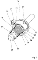
- FIG. 1 is an exploded a schematic view of a drive unit having the features of the present invention with open housing;
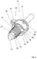
- FIG. 2 is a perspective top view of the drive unit of FIG. 1 with removed upper housing part;
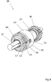
- FIG. 3 is a view similar to FIG. 2 with partly disassembled other differential gear
- FIG. 4 is a schematic view of the other differential gear in a lateral view for illustrating the stopping function
- FIG. 5 is a view similar to FIG. 4 in a state for achieving another completely closed, rotated position of the vertical slats;
- FIG. 6 is a view similar to FIGS. 4 and 5 of a state for again achieving a partly open rotated position for displacing the vertical slats;
- FIG. 7 is a schematic view of a drive unit with removed upper housing part as another exemplary embodiment of the present invention.
- FIG. 8 is a schematic view of another embodiment of another differential gear
- FIG. 9 is an enlarged partial view of a front surface of the other differential gear
- FIG. 10 is a schematic rear view of the other differential gear of FIG. 8 ;
- FIG. 11 is a top view of the drive unit of FIG. 7 ;
- FIG. 12 is a view similar to FIG. 11 in a released state of the snap-in coupling.
- FIG. 1 shows a schematic view of a drive unit 10 with the features of the present invention.
- the drive unit is used for driving a vertical Venetian blind not shown in FIG. 1 .
- the drive unit 10 has an upper housing part 11 and a lower housing part 12 , wherein in FIG. 1 the upper housing part 11 is shown removed from the lower housing part 12 .
- a differential gear 13 and another differential gear 14 are mounted at the lower housing part 12 .
- the differential gear is a planet gear 13 and the other differential gear is a differential gear 14 .
- the planet gear 13 and the differential gear 14 have a shared actuating element 15 , namely a chain wheel 15 .
- the chain wheel 15 is connected to a central wheel (not shown in FIG. 1 ) of the planet gear 13 in a manner adapted to rotate in unison.
- the planet gear 13 has a first driven element 17 and a second driven element 16 .
- the first driven element 17 in this embodiment is an outer ring 17 on the outer circumference of the planet gear 13 , namely on the planet carrier, and the second driven element 16 is a bevel gear 16 .
- a toothed wheel 18 meshes with the outer ring 17 .
- the toothed wheel 18 is used as the other driving element for the differential gear 14 .
- the toothed wheel 18 is connected to a bevel gear (not shown in the figure) of the differential gear 14 in a manner adapted to rotate in unison.
- the toothed wheel 18 is connected by means of a leg spring 19 to a bushing 20 of the differential gear 14 , as is explained in detail below.
- the bushing 20 is used as the housing of the differential gear 14 .
- a spline shaft 21 extends through the differential gear 14 and the toothed wheel 18 and is connected to a bevel gear (not shown FIG. 1 ) of the differential gear 14 as the other first driven element.
- the bushing 20 has a spiral 22 on its outer circumference as the other second driven element of the differential gear 14 .
- a stop element 24 is pivotably arranged about an axle 23 .
- the stop element 24 has a toothed ring section 25 .
- FIG. 2 shows a view of the drive unit 10 with the upper housing part removed.
- the toothed ring section 25 has six teeth, so that six revolutions of the bushing 20 are possible.
- a front surface of the spiral 22 in each case stops at the stop element 24 in the known manner.
- FIG. 3 shows a view similar to FIG. 2 , whereby the bushing 20 is removed from the differential gear 14 .
- the leg spring 19 has a leg 26 , which meshes with the bushing 20 in the mounted state.
- the toothed wheel 18 is connected by means of a sleeve 27 to a bevel gear 28 of the differential gear 14 in a manner adapted to rotate in unison.
- the leg spring 19 is arranged on the sleeve 27 , and a leg of the leg spring turned away from the leg 26 is connected to the toothed wheel 18 in a manner adapted to rotate in unison.
- the differential gear has, besides the bevel gear 28 , two other bevel gears 29 , 30 , which are each mounted rotatably at the bushing 20 by means of axles 31 .
- Each of the bevel gears 29 , 30 meshes on one side with the bevel gear 28 and at the end turned away from same with another bevel gear 32 , which forms the other first driven element of the differential gear 14 .
- the bevel gear 32 is connected to the spline shaft 21 in a manner adapted to rotate in unison.
- FIG. 4 shows the differential gear 14 in a lateral view, as viewed from the toothed wheel 18 .
- the sleeve 27 has a mount 33 for a leg at the end of the leg spring 19 turned away from the leg 26 .
- Another mount 34 is arranged at the bushing 20 and meshes with the leg 26 .
- the bushing 20 has, moreover, a stop 35 , which, in the exemplary embodiment shown, is a thickened section with rectangular cross section, in the middle of which the mount 34 is formed as a blind hole.
- a stop 36 is arranged at the bevel gear 28 , which interacts with the stop 35 .
- the leg spring 19 is pretensioned in such a way that the stops 35 , 36 are held against one another in the position shown.
- FIG. 5 and FIG. 6 each show a view similar to FIG. 4 , wherein a leg 37 of the leg spring 19 arranged in the mount 33 is shown, moreover, in FIG. 6 .
- the chain wheel 15 is actuated by means of a ball chain not shown in the figures.
- the differential gear 14 is in the state shown in FIG. 6 , in which the stop element 24 stops at a front end of the spiral 22 and the stop 36 in FIG. 6 comes into contact with the stop 35 from above.
- the leg spring 19 is tensioned by one revolution. Since the displacing motion of the vertical slats is tighter than the rotation motion thereof, the toothed wheel 18 is now first driven via the outer ring 17 when the chain wheel 15 is actuated.
- the stop 36 is brought into the position under the stop 35 shown in FIG. 5 , while the leg spring 19 is released.
- the vertical slats are then brought into a closed position by means of driving the spline shaft 21 via the bevel gears 28 , 29 , 30 , 32 from an approximately 30° open position with stationary bushing 20 .
- the bushing 20 is rotated over the stop 36 and the stop 35 to the extent that the stop element 24 is located in its opposite stop positions compared to FIGS. 5 and 6 and the spiral 22 stops at its other front end at the stop element 24 .
- the vertical slats are then rotated into their closed, final position.
- the bevel gear 16 is driven because of the now blocked toothed wheel 18 and thus also because of the blocked toothed wheel 17 .
- the bevel gear 16 meshes with a driving gear for a pull cord for displacing the vertical slats.
- the vertical slats are then displaced into their completely closed, final position.
- the chain wheel 15 is actuated in the opposite direction.
- the vertical slats are rotated here in the opposite direction by the sleeve 20 being rotated by means of actuating the toothed wheel 18 via the outer ring 17 by means of the spring force of the leg spring 19 to the extent that the stop element 24 has been rotated from the position shown in FIG. 4 into the position shown in FIG. 5 .
- the chain wheel 15 can be further actuated in the same direction. Because the spiral 22 stops at the stop element 24 and thus prevents a further rotation of the bushing 20 , the bevel gear 28 can be rotated one revolution further against the bushing 20 while tensioning the leg spring 19 until the stop 36 comes to lie at the stop 35 as shown in FIG. 6 from above. Because the bevel gear 28 meshes with the bevel gears 29 , 30 , the rotary motion of the bevel gear 28 is converted via the bevel gears 29 , 30 to the bevel gear 32 into a rotary motion of same in the opposite direction. The vertical slats are rotated by means of the spline shaft 21 for an opening into an approximately 30° opened position.
- a further actuation of the chain wheel 15 then leads to a displacing of the vertical slats via the bevel gear 16 for opening the vertical Venetian blind because of the differential gear 14 , which is now blocked in this position. Because of the approximately 30° opened position of the vertical slats, they cannot get hooked up when brought together into a pack.
- FIG. 7 shows a schematic view of a drive unit 38 as another exemplary embodiment of the present invention.
- the drive unit 38 essentially corresponds to the drive unit 10 . Identical elements have the same reference numbers.
- the drive unit 38 has another differential gear 39 .
- the other differential gear is likewise a differential gear 39 .
- the other differential gear 39 essentially corresponds to the other differential gear 14 .
- the other differential gear 39 does not have a leg spring 19 .
- FIG. 7 does not show the housing of the other differential gear 39 .
- the other differential gear 39 has a bevel gear 40 instead of the bevel gear 32 .
- a part of the outer circumference of the bevel gear 40 is embodied as a spring section 41 .
- the spring section 41 protrudes a little bit over the outer circumference of the remaining circumference of the bevel gear 40 .
- the spring section 41 is pretensioned radially in the outward direction.
- the spring section 41 has a front surface 42 at the lower end.
- FIG. 8 shows a perspective view of the differential gear 39 .
- the differential gear 39 has a bushing 43 , similar to the bushing 20 , as a housing.
- the bushing 43 likewise has a spiral 44 similar to the spiral 22 as the other second driven element.
- the spiral 44 has, however, more than one turn.
- a second turn section 45 which is arranged on a spring section 46 , is connected to the first turn of the spiral 44 .
- the spring section 46 is embodied as a continuation of the circumference of the bushing 43 in the area of the spiral 44 .
- the spring section 46 On its side turned away from the second turn section 45 , the spring section 46 has a web 47 .
- FIG. 9 shows an enlarged partial view of the front side of the bushing 43 .
- a mount which is turned towards the web 47 and is assigned to the spiral 44 , for the front surface 42 of the spring section 41 , is arranged at the bushing 43 .
- the front surface 42 actively meshes with the mount 48 , so that a coupled state of the snap-in coupling is produced.
- the bevel gear 40 and the bushing 43 and thus the spiral 44 are connected by means of the front surface 42 and the mount 48 to one another in a manner adapted to rotate in unison.
- FIG. 10 shows a perspective rear view of the differential gear 39 similar to the view of FIG. 4 .
- FIG. 11 shows a top view of the drive unit 38 in a coupled state and
- FIG. 12 shows a top view of the drive unit 38 in a released state of the coupling.
- the mode of operation of the drive unit 38 is explained in detail below on the basis of FIGS. 7 through 12 .
- the mode of operation essentially corresponds to that of the drive unit 10 .
- a different mode of operation arises when turning the vertical slats for complete closing in the opposite direction in the extended position.
- the spring section 41 actively meshes with the mount 48 , as shown in FIG. 9 .
- the stop 36 stops at the stop 35 from below, and a front end of the spiral 44 abuts against the stop element 24 , as shown in FIG. 11 .
- the chain wheel 15 is actuated in the opposite direction.
- the vertical slats are rotated in the opposite direction by the sleeve 43 being rotated by means of actuating the toothed wheel 18 via the outer ring 17 by the active meshing of the spring section 41 and of the mount 48 to the extent that the stop element 24 has been rotated from the position shown in FIG. 11 into the position shown in FIG. 12 .
- the vertical slats are completely closed in the opposite direction.
- the chain wheel 15 can now be further actuated in the same direction as for rotating.
- the stop 24 now presses the spring section 46 in FIG. 9 radially in the inward direction via the second turn section 45 , the spring section 41 is pressed via the web 47 radially inwardly to the extent that the front surface 42 no longer meshes with the mount 48 .
- the bushing 43 cannot be further rotated counterclockwise in FIGS. 8 and 9 because of the stopping of the spiral 44 at the stop element 24 .
- the toothed wheel 18 can be further rotated by one revolution until it lies on the stop 35 from above in FIG. 10 after one clockwise rotation of the stop 36 .
Landscapes
- Engineering & Computer Science (AREA)
- Structural Engineering (AREA)
- Architecture (AREA)
- Civil Engineering (AREA)
- Blinds (AREA)
Abstract
Description
- 10 Drive unit
- 11 Upper housing part
- 12 Lower housing part
- 13 Planet gear
- 14 Differential gear
- 15 Chain wheel
- 16 Bevel gear
- 17 Outer ring
- 18 Toothed wheel
- 19 Leg spring
- 20 Bushing
- 21 Spline shaft
- 22 Spiral
- 23 Axle
- 24 Stop element
- 25 Toothed ring section
- 26 Leg
- 27 Sleeve
- 28 Bevel gear
- 29 Bevel gear
- 30 Bevel gear
- 31 Axle
- 32 Bevel gear
- 33 Mount
- 34 Mount
- 35 Stop
- 36 Stop
- 37 Leg
- 38 Drive unit
- 39 Differential gear
- 40 Bevel gear
- 41 Spring section
- 42 Front surface
- 43 Bushing
- 44 Spiral
- 45 Second spiral section
- 46 Spring section
- 47 Web
- 48 Mount
Claims (20)
Applications Claiming Priority (6)
| Application Number | Priority Date | Filing Date | Title |
|---|---|---|---|
| DE102006023789 | 2006-05-16 | ||
| DE102006023789.7 | 2006-05-16 | ||
| DE200610023789 DE102006023789A1 (en) | 2006-05-16 | 2006-05-16 | Drive unit for vertical louvre shutter has a common drive for both tilt and sliding adjustment and with an additional differential for the first drive unit |
| DE202007000605U DE202007000605U1 (en) | 2006-05-16 | 2007-01-10 | Drive unit for vertical louvre shutter has a common drive for both tilt and sliding adjustment and with an additional differential for the first drive unit |
| DE202007000605U | 2007-01-10 | ||
| DE202007000605.5 | 2007-01-10 |
Publications (2)
| Publication Number | Publication Date |
|---|---|
| US20070267154A1 US20070267154A1 (en) | 2007-11-22 |
| US7717153B2 true US7717153B2 (en) | 2010-05-18 |
Family
ID=38266356
Family Applications (1)
| Application Number | Title | Priority Date | Filing Date |
|---|---|---|---|
| US11/748,763 Active 2028-03-21 US7717153B2 (en) | 2006-05-16 | 2007-05-15 | Drive unit for a vertical venetian blind |
Country Status (4)
| Country | Link |
|---|---|
| US (1) | US7717153B2 (en) |
| EP (1) | EP1857629B1 (en) |
| DE (1) | DE202007000605U1 (en) |
| DK (1) | DK1857629T3 (en) |
Cited By (3)
| Publication number | Priority date | Publication date | Assignee | Title |
|---|---|---|---|---|
| US9797191B2 (en) * | 2016-02-05 | 2017-10-24 | Taicang Kingfu Plastic Manufacture Co. Ltd. | Driving device for window blind |
| US11142944B2 (en) | 2017-12-28 | 2021-10-12 | Home Depot Product Authority, Llc | Slat angle adjustment mechanism for window blinds |
| US12460475B2 (en) | 2017-12-28 | 2025-11-04 | Home Depot Product Authority, Llc | Motorized slat angle adjustment mechanism for window blinds |
Families Citing this family (4)
| Publication number | Priority date | Publication date | Assignee | Title |
|---|---|---|---|---|
| DE202007000605U1 (en) * | 2006-05-16 | 2007-07-12 | Vkr Holding A/S | Drive unit for vertical louvre shutter has a common drive for both tilt and sliding adjustment and with an additional differential for the first drive unit |
| TWM457501U (en) * | 2013-02-07 | 2013-07-21 | Ke-Ming Lin | Wire guide device of window curtain |
| CN108759216B (en) * | 2018-05-21 | 2020-11-20 | 海尔智家股份有限公司 | Ice crusher and refrigerator |
| CN108759218B (en) * | 2018-05-21 | 2020-11-20 | 海尔智家股份有限公司 | Ice crusher and refrigerator |
Citations (7)
| Publication number | Priority date | Publication date | Assignee | Title |
|---|---|---|---|---|
| US3463219A (en) * | 1966-10-10 | 1969-08-26 | Schenker Storen Maschf | Blind for windows or the like |
| US3878877A (en) * | 1972-08-08 | 1975-04-22 | Paul Bruneau | Vertical blinds |
| US4316493A (en) * | 1977-08-15 | 1982-02-23 | Arena Joseph Philip | Vertical blind controls |
| DE19525139A1 (en) | 1995-07-11 | 1997-01-23 | Benthin Ag | Vertical blind with a crank rod for actuation |
| US5771953A (en) * | 1995-07-11 | 1998-06-30 | Benthin Aktiengesellschaft | Vertical blind with a crank rod |
| US5845695A (en) * | 1997-05-05 | 1998-12-08 | All-Teck Blinds, P.T.B. Inc. | Traversing and rotating wand for vertical blinds |
| US20070267154A1 (en) * | 2006-05-16 | 2007-11-22 | Gramsch Wilfried | Drive unit for a vertical venetian blind |
Family Cites Families (3)
| Publication number | Priority date | Publication date | Assignee | Title |
|---|---|---|---|---|
| DE2128643A1 (en) * | 1971-06-09 | 1973-01-04 | Herbert Marder Feinwerktechnik | DRIVE DEVICE FOR SLAT CURTAINS OR DGL |
| DE2737416C2 (en) * | 1976-11-26 | 1987-01-22 | Walter 7859 Efringen-Kirchen Hügin | Drive device for slatted blinds |
| DE4131478A1 (en) * | 1991-09-21 | 1993-03-25 | Benthin Management Gmbh | VERTICAL BLINDS WITH ONE-ORGAN DRIVE |
-
2007
- 2007-01-10 DE DE202007000605U patent/DE202007000605U1/en not_active Expired - Lifetime
- 2007-05-15 US US11/748,763 patent/US7717153B2/en active Active
- 2007-05-15 EP EP07108279.6A patent/EP1857629B1/en active Active
- 2007-05-15 DK DK07108279.6T patent/DK1857629T3/en active
Patent Citations (9)
| Publication number | Priority date | Publication date | Assignee | Title |
|---|---|---|---|---|
| US3463219A (en) * | 1966-10-10 | 1969-08-26 | Schenker Storen Maschf | Blind for windows or the like |
| US3878877A (en) * | 1972-08-08 | 1975-04-22 | Paul Bruneau | Vertical blinds |
| US4316493A (en) * | 1977-08-15 | 1982-02-23 | Arena Joseph Philip | Vertical blind controls |
| US4316493B1 (en) * | 1977-08-15 | 1997-06-24 | Newell Operating Co | Vertical blind controls |
| DE19525139A1 (en) | 1995-07-11 | 1997-01-23 | Benthin Ag | Vertical blind with a crank rod for actuation |
| US5749406A (en) | 1995-07-11 | 1998-05-12 | Benthin Aktiengesellschaft | Vertical blind with a crank rod for operation |
| US5771953A (en) * | 1995-07-11 | 1998-06-30 | Benthin Aktiengesellschaft | Vertical blind with a crank rod |
| US5845695A (en) * | 1997-05-05 | 1998-12-08 | All-Teck Blinds, P.T.B. Inc. | Traversing and rotating wand for vertical blinds |
| US20070267154A1 (en) * | 2006-05-16 | 2007-11-22 | Gramsch Wilfried | Drive unit for a vertical venetian blind |
Cited By (3)
| Publication number | Priority date | Publication date | Assignee | Title |
|---|---|---|---|---|
| US9797191B2 (en) * | 2016-02-05 | 2017-10-24 | Taicang Kingfu Plastic Manufacture Co. Ltd. | Driving device for window blind |
| US11142944B2 (en) | 2017-12-28 | 2021-10-12 | Home Depot Product Authority, Llc | Slat angle adjustment mechanism for window blinds |
| US12460475B2 (en) | 2017-12-28 | 2025-11-04 | Home Depot Product Authority, Llc | Motorized slat angle adjustment mechanism for window blinds |
Also Published As
| Publication number | Publication date |
|---|---|
| DK1857629T3 (en) | 2015-09-28 |
| DE202007000605U1 (en) | 2007-07-12 |
| EP1857629B1 (en) | 2015-06-24 |
| EP1857629A3 (en) | 2011-03-16 |
| US20070267154A1 (en) | 2007-11-22 |
| EP1857629A2 (en) | 2007-11-21 |
Similar Documents
| Publication | Publication Date | Title |
|---|---|---|
| US7717153B2 (en) | Drive unit for a vertical venetian blind | |
| US8876646B2 (en) | Drive for a movable furniture part | |
| US3194366A (en) | Self-braking driving device for an operating shaft | |
| EP2617639A1 (en) | Bicycle gear, especially in the form of a multiple gear hub | |
| US5266068A (en) | Vertical blind with single-element drive | |
| US1225144A (en) | Clutch mechanism for transmission-gearings. | |
| JP2014119093A (en) | Driving force transmission system and sunshade device for vehicle | |
| JP2004218735A (en) | Actuator for valve with manual operation mechanism | |
| US20100186906A1 (en) | Device for driving and turning the slats of a Venetian blind | |
| CN217999320U (en) | A transmission mechanism, an automatic manual window opener and a window | |
| US20220145698A1 (en) | Folding/unfolding device for a window shade | |
| MX2007004252A (en) | Anti-spin/anti-drift module. | |
| JP2020200637A (en) | Driving device for blind | |
| CN113503104A (en) | Transmission mechanism, manual-automatic integrated window opener and window | |
| JP5349392B2 (en) | Gearbox and Greenhouse Seat Opener with Gearbox | |
| JPH0569343A (en) | Open-end wrench | |
| JPH0564391U (en) | Jalousie windows | |
| KR200237016Y1 (en) | Ventilating unit for vinyl house | |
| US12151919B2 (en) | Winch clutch and winch thereof | |
| JP4569717B1 (en) | Automatic door | |
| JP6783678B2 (en) | Rotation control device | |
| JPH0545758Y2 (en) | ||
| JP4153635B2 (en) | Window opening and closing device | |
| JP2730376B2 (en) | Cabin window opening and closing device for industrial vehicles | |
| CN205189721U (en) | Dual -drive switcher of transmission mechanism of blind window |
Legal Events
| Date | Code | Title | Description |
|---|---|---|---|
| AS | Assignment |
Owner name: VKR HOLDING A/S, DENMARK Free format text: ASSIGNMENT OF ASSIGNORS INTEREST;ASSIGNOR:GRAMSCH, WILFRIED;REEL/FRAME:019295/0550 Effective date: 20070511 Owner name: VKR HOLDING A/S,DENMARK Free format text: ASSIGNMENT OF ASSIGNORS INTEREST;ASSIGNOR:GRAMSCH, WILFRIED;REEL/FRAME:019295/0550 Effective date: 20070511 |
|
| STCF | Information on status: patent grant |
Free format text: PATENTED CASE |
|
| AS | Assignment |
Owner name: HUNTER DOUGLAS INDUSTRIES SWITZERLAND GMBH, SWITZE Free format text: ASSIGNMENT OF ASSIGNORS INTEREST;ASSIGNOR:VKR HOLDLING A/S;REEL/FRAME:026221/0925 Effective date: 20100622 |
|
| FPAY | Fee payment |
Year of fee payment: 4 |
|
| FEPP | Fee payment procedure |
Free format text: 7.5 YR SURCHARGE - LATE PMT W/IN 6 MO, LARGE ENTITY (ORIGINAL EVENT CODE: M1555) |
|
| MAFP | Maintenance fee payment |
Free format text: PAYMENT OF MAINTENANCE FEE, 8TH YEAR, LARGE ENTITY (ORIGINAL EVENT CODE: M1552) Year of fee payment: 8 |
|
| MAFP | Maintenance fee payment |
Free format text: PAYMENT OF MAINTENANCE FEE, 12TH YEAR, LARGE ENTITY (ORIGINAL EVENT CODE: M1553); ENTITY STATUS OF PATENT OWNER: LARGE ENTITY Year of fee payment: 12 |