US7715401B2 - Router - Google Patents
Router Download PDFInfo
- Publication number
- US7715401B2 US7715401B2 US12/031,856 US3185608A US7715401B2 US 7715401 B2 US7715401 B2 US 7715401B2 US 3185608 A US3185608 A US 3185608A US 7715401 B2 US7715401 B2 US 7715401B2
- Authority
- US
- United States
- Prior art keywords
- qos
- processing
- sip
- network side
- session control
- Prior art date
- Legal status (The legal status is an assumption and is not a legal conclusion. Google has not performed a legal analysis and makes no representation as to the accuracy of the status listed.)
- Expired - Fee Related, expires
Links
Images


Classifications
-
- H—ELECTRICITY
- H04—ELECTRIC COMMUNICATION TECHNIQUE
- H04L—TRANSMISSION OF DIGITAL INFORMATION, e.g. TELEGRAPHIC COMMUNICATION
- H04L45/00—Routing or path finding of packets in data switching networks
-
- H—ELECTRICITY
- H04—ELECTRIC COMMUNICATION TECHNIQUE
- H04L—TRANSMISSION OF DIGITAL INFORMATION, e.g. TELEGRAPHIC COMMUNICATION
- H04L45/00—Routing or path finding of packets in data switching networks
- H04L45/302—Route determination based on requested QoS
- H04L45/306—Route determination based on the nature of the carried application
-
- H—ELECTRICITY
- H04—ELECTRIC COMMUNICATION TECHNIQUE
- H04L—TRANSMISSION OF DIGITAL INFORMATION, e.g. TELEGRAPHIC COMMUNICATION
- H04L65/00—Network arrangements, protocols or services for supporting real-time applications in data packet communication
- H04L65/1066—Session management
- H04L65/1101—Session protocols
- H04L65/1104—Session initiation protocol [SIP]
-
- H—ELECTRICITY
- H04—ELECTRIC COMMUNICATION TECHNIQUE
- H04L—TRANSMISSION OF DIGITAL INFORMATION, e.g. TELEGRAPHIC COMMUNICATION
- H04L65/00—Network arrangements, protocols or services for supporting real-time applications in data packet communication
- H04L65/80—Responding to QoS
Definitions
- the present invention relates to a router.
- ToS/DSCP Type of Service/Differentiated Service Code Point marking
- PDSN Packet Data Serving Node
- the present invention has been made in view of the above circumstances, and its object is to approximately perform QoS processing even when session control traffic such as SIP traffic to be unitarily subjected to QoS management by managers of session control networks such as SIP networks, and loopback traffic to be freely subjected to QoS management by users coexist.
- an edge router is provided with SIP proxy functions to make it an outbound SIP proxy through which SIP signaling and SIP traffic outside an SIP network never fail to pass.
- Two tables are provided to associate SIP messages with QoS setting information; one can be set by only SIP network managers, and the other can be set by user network managers as well.
- the SIP proxy functions on the edge router check a routing table and the address information of SIP message to derive an SIP stream direction.
- QoS setting information can be determined and set in a QoS function unit.
- QoS setting information can be determined and set in the QoS function unit.
- a solution means of the present invention is a router that includes a session control proxy function and a function to perform QoS processing for packets, and performs communication between a user network including a terminal and a session control service provider network.
- the router includes: a first QoS setting content description table that can be set by a service provider that provides session control services, and stores the setting contents of QoS processing, correspondent to a communication direction and the stream attribute of a session control message; a second QoS setting content description table that can be set by a service provider that provides session control services and a user network manager, and stores the setting contents of QoS processing, correspondent to a communication direction and the stream attribute of a session control message; a QoS/filtering function unit that performs QoS processing, based on the setting content of the QoS processing; and a processing unit that analyzes a session control message in the session control proxy function, refers to the first and the second QoS setting content description tables, and determines the setting content of QoS processing of the Q
- the processing unit extracts communication information containing a destination address and a sender address, and stream attributes from a received response message from a destination terminal.
- the processing unit determines a communication direction according to a combination of whether a destination is in a user network side or session service provider side, and whether a sender is in the user network side or the session service provider side, based on the extracted destination address and the sender address.
- the processing unit when the communication direction of the session control message passes through the session control service provider network, refers to the first QoS setting content description table.
- the processing unit refers to the second QoS setting content description table, searches the setting content of QoS processing, based on the communication direction and the stream attribute, and sets the setting content in the QoS/filtering processing unit, based on the session control message containing the destination address and the sender address.
- FIG. 1 is a sequence diagram of this embodiment (a call issued from a terminal 2 a passes through an SIP network);
- FIG. 2 is a sequence diagram of this embodiment (user network loopback);
- FIG. 3 is a sequence diagram of this embodiment (a call to arrive in a terminal 2 a passes through an SIP network);
- FIG. 4 is a sequence diagram of this embodiment (SIP service provider loopback);
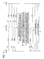
- FIG. 5 is a flowchart of SIP analysis and QoS setting processing
- FIG. 6 is a drawing showing an example of a network to which this embodiment is applied.
- FIG. 7 is a device configuration drawing of an edge router
- FIG. 8 illustrates an example of an SIP message-QoS/filtering setting action correspondence table of service provider side
- FIG. 9 illustrates an example of an SIP message-QoS/filtering setting action correspondence table of user side
- FIG. 10 illustrates an example of a 200 OK message that passes through an SIP network.
- FIG. 6 is a drawing of a typical network to which this embodiment is applied.
- an edge router 1 of an embodiment of the present invention an SIP proxy server 4 that provides SIP services, and routers 7 , 8 , and 9 that constitute the network are connected.
- the above devices are ones that can be directly managed by the service provider that provides SIP services.
- user networks 5 a and 5 b are connected via an edge router 1
- SIP terminals 2 a and 2 b are connected via the user networks 5 a and 5 b , respectively.
- the edge router 1 defaults to the router 7 , and IP packets arriving in the edge router 1 , except those directed to LAN, are transmitted to the router 7 .
- SIP terminals 3 and 10 not under control of the edge router 1 are connected with the edge routers 9 and 11 .
- the terminal addresses of SIP terminals 2 a , 2 b , 3 , and 10 , the LAN addresses a and b, and WAN address of the edge router 1 , the address of the router 7 , the network address of LAN are shown in the drawing. In the drawing, for example, the edge router 1 and its right side correspond to WAN, and the edge router 1 and its left side correspond to LAN.
- FIG. 7 is a device block diagram of the edge router 1 .
- the edge router 1 is a common router system in which, for example, a CPU 101 , memory 102 , and NIF 103 a , NIF 103 b , NIF 103 w are connected through a bus 104 .
- the memory includes a TCP/IP stack in which a routing table 10211 for normal packet transfer, and QoS/filtering function unit 10212 that performs packet marking, shaping/polishing, and filtering exist.
- a socket interface 10213 for providing TCP/IP communication functions to applications exists. This is an interface that abstracts IP address, port number, protocol, and the like, thereby enabling applications to perform processing with only payload within packets in mind. If necessary, the address and port number of a sender can be taken out additionally.
- SIP proxy software processing unit
- SIP proxy SIP proxy software processing unit
- correspondence tables 1023 and 1024 for deciding the contents of settings to the QoS/filtering function unit from the contents of an SIP message.
- the correspondence table 1023 can be set by only service providers that provide SIP services, and the correspondence table 1024 can be set not only by service providers that provide SIP services, but also by user network managers.
- TCP/IP stack for packet transfer is implemented by software. However, it may be implemented by hardware and connected through the bus 104 .
- FIG. 8 is an example of an SIP message-QoS/filtering setting action correspondence table 1023 of the service provider side.
- the correspondence table 1023 stores setting actions of QoS processing, corresponding to communication directions and stream attributes (media, attribute) SIP 200 OK messages.
- the asterisk (*) indicates that the field is optional.
- the first line 10231 of the table supposes a bidirectional audio application such as VoIP.
- the SIP proxy 1022 SIP analysis/QoS setting processing unit 10221 ) performs the setting of “marking a packet having a sender address S, destination address D, and use port P by EF (Expedited Forwarding of the highest priority) and shaping in a band B” in the QoS/filtering function part 10212 , wherein the SIP 200 OK message has the media column having a media element of audio and a proto element of RTP/AVP (Realtime Transport Protocol/Audio Video Profile) and attribute of sendrecv (bidirectional).
- RTP/AVP Realtime Transport Protocol/Audio Video Profile
- the sender address S, destination address D, use port P, and band B are setting parameters extracted from an SDP unit of the SIP 200 OK message.
- the second line 10232 of the table supposes a unidirectional image application such as VoD.
- the SIP proxy 1022 SIP analysis/QoS setting processing unit 10221 ) performs the setting of “marking a packet having a sender address S, destination address D, and use port P by AF43 (Assured Forwarding of high priority) and shaping in a band B” in the QoS/filtering function part 10212 .
- the last line 10233 of the table means the setting to the QoS/filtering function part 10212 when an SIP 200 OK message received by the edge router 1 does not meet any of conditions set previously, and the SIP proxy 1022 (SIP analysis/QoS setting processing unit 10221 ) sets traffic of the lowest priority of “marking a packet having a sender address S, destination address D, and use port P by BE (Best Effort) and polishing in a band B.”
- the contents of the correspondence table 1024 are the same as the above-described correspondence table 1023 , except that direction is limited to inbound (LAN).
- FIG. 10 is part of an example of a 200 OK message. Elements not directly related this embodiment are omitted as required.
- the destination address D described above is extracted from the last line of Via: line existing in the SIP header unit of the SIP 200 OK message.
- FIG. 1 is a sequence diagram when a call issued from a terminal 2 a to which this embodiment is applied passes through an SIP network.
- An SIP INVITE message issued from the terminal 2 a is temporarily put into proxy in the edge router 1 (s 1 ) before being transferred to an SIP proxy server 4 , which provides actual services (s 2 ).
- the server 4 transfers an INVITE message to a terminal 3 being a transmission party (s 3 ).
- the terminal 3 transmits an SIP Trying message, then an SIP Ringing message to the terminal 2 .
- the two messages arrive in the terminal 2 through a route reverse to INVITE (s 4 , s 5 , s 6 , s 7 , s 8 , s 9 ).
- the terminal 3 transmits a 200 OK message (s 10 ).
- the 200 OK message arrives in the edge router 1 via the server 4 (s 11 ).
- the edge router 1 analyzes an SIP message (including SDP) of 200 OK, and extracts communications information such as destination/sender IP address, use port number, and protocol, and stream attributes such as band, media, and attribute (p 1 ).
- the edge router 1 checks the extracted destination/sender IP address and the routing table and the like to extract a corresponding interface, and determines a communication direction, based on it (p 2 ).
- the edge router 1 Since the communication direction is a direction that passes through the SIP network (outbound direction with sender of WAN and destination of LAN: described later in f 13 ), the edge router 1 searches the SIP message-QoS/filtering action correspondence table 1023 of service provider side from the stream attributes and other information, and sets results in the QoS/filtering processing unit (p 3 ). Processing for determining a communication direction and the selection of a correspondence table to be used will be detailed in “3. QoS Setting Flowchart.” After that, the edge router 1 transmits a 200 OK message to the terminal 2 (s 12 ).
- the terminal 2 a that receives it transmits ACK to the terminal 3 (s 13 ), the SIP sequence is completed, and user traffic can be exchanged between the terminals 2 a and 3 .
- the edge router 1 performs no special processing for traffic from the terminal 3 to the terminal 2 a (s 15 ), it performs QoS/filtering processing for traffic from the terminal 2 a to the terminal 3 (s 14 ) according to the setting performed in p 3 (p 4 ).
- FIG. 2 is a sequence diagram showing user network loopback to which this embodiment is applied.
- An SIP INVITE message issued from the terminal 2 a arrives in the terminal 2 b via the edge router 1 (s 21 , s 22 ).
- the terminal 2 b transmits an SIP Trying message, and then an SIP Ringing message to the terminal 2 a .
- the two messages arrive in the terminal 2 a through a route reverse to INVITE (s 23 , s 24 , s 25 , s 26 ).
- the terminal 2 b On completion of a preparation to receive INVITE from the terminal 2 a , the terminal 2 b transmits a 200 OK message (s 27 ).
- the 200 OK message arrives in the edge router 1 .
- the edge router 1 On receiving the 200 OK message, the edge router 1 analyzes an SIP message (including SDP) of 200 OK, and extracts communication information such as IP address and port number, and stream attributes such as band, media, and attribute (p 1 ). The edge router 1 checks the extracted destination/sender IP address and the routing table and the like to extract a corresponding interface, and determines a communication direction, based on it (p 2 ). Since the communication direction is user network loopback (turnaround (LAN) with sender and destination in LAN: described later in f 14 ), the edge router 1 searches the SIP message-QoS/filtering action correspondence table 1023 of user side from the stream attributes and other information, and sets results in the QoS/filtering processing unit (p 5 ).
- SIP message including SDP
- LAN turnaround
- the edge router 1 transmits a 200 OK message to the terminal 2 a (s 28 ).
- the terminal 2 a that receives it transmits ACK to the terminal 2 b (s 13 ), the SIP sequence is completed, and user traffic can be exchanged between the terminals 2 a and 2 b .
- QoS/filtering processing is performed according to the setting performed in p 5 (p 4 , p 6 ).
- FIG. 3 is a sequence diagram when a call to arrive in a terminal 2 a to which this embodiment is applied passes through an SIP network.
- An SIP INVITE message issued from the terminal 3 is temporarily put into proxy in an SIP proxy server that provides actual services (s 41 ), before being transferred to the edge router 1 (s 42 ).
- the edge router 1 transfers an INVITE message to the terminal 2 a being a transmission party (s 43 ).
- the terminal 2 a transmits an SIP Trying message, then an SIP Ringing message to the terminal 3 .
- the two messages arrive in the terminal 3 through a route reverse to INVITE (s 44 , s 45 , s 46 , s 47 , s 48 , s 49 ).
- the terminal 2 a transmits a 200 OK message (s 50 ).
- the 200 OK message arrives in the edge router 1 via the server 4 (s 11 ).
- the edge router 1 analyzes an SIP message (including SDP) of 200 OK, and extracts communications information such as IP address and port number, and stream attributes such as band, media, and attribute (p 1 ).
- the edge router 1 checks the extracted destination/sender IP address and the routing table and the like to extract a corresponding interface, and determines a communication direction, based on it (p 2 ). Since the communication direction is a direction that passes through the SIP network (inbound direction with sender of LAN and destination of WAN: described later in f 10 ), the edge router 1 searches the SIP message-QoS/filtering action correspondence table 1023 of service provider side from the stream attributes and other information, and sets results in the QoS/filtering processing unit (p 3 ). Processing for determining a communication direction and the selection of a correspondence table to be used will be detailed in “3.
- the edge router 1 transmits 200 OK to the terminal 3 via the server 4 (s 52 ), the server 4 transfers it to the terminal 3 (s 53 ), the terminal 3 that receives it transmits ACK to the terminal 2 a , SIP sequence is completed, and user traffic can be exchanged between the terminals 2 a and 3 .
- the edge router 1 performs no special processing for traffic from the terminal 3 to the terminal 2 (s 54 ), it performs QoS/filtering processing for traffic from the terminal 2 a to the terminal 3 (s 55 ) according to the setting performed in p 3 (p 4 ).
- FIG. 4 is a sequence diagram showing user network loopback to which this embodiment is applied.
- An SIP INVITE message issued from the terminal 3 arrives in the terminal 4 via the edge router 1 (s 61 , s 62 ).
- the two messages arrive in the terminal 3 through a route reverse to INVITE (s 63 , s 64 , s 65 , s 66 ).
- the terminal 4 transmits a 200 OK message (s 67 )
- the 200 OK message arrives in the edge router 1 .
- the edge router 1 On receiving the 200 OK message, the edge router 1 analyzes an SIP message (including SDP) of 200 OK, and extracts communications information such as IP address and port number, and stream attributes such as band, media, and attribute (p 1 ). The edge router 1 checks the extracted destination/sender IP address and the routing table and the like to extract a corresponding interface, and determines a communication direction, based on it (p 2 ). Since the communication direction is user network loopback (turnaround (WAN) with sender and destination addresses in WAN: described later in f 9 ), the edge router 1 searches the SIP message-QoS/filtering action correspondence table 1024 of user side from the stream attributes and other information, and sets results in the QoS/filtering processing unit (p 7 ).
- SIP message including SDP
- WAN turnaround
- the edge router 1 transmits a 200 OK message to the terminal 3 (s 68 ).
- the terminal 3 that receives it transmits ACK to the terminal 4 (s 69 ), the SIP sequence is completed, and user traffic can be exchanged between the terminals 3 and 4 .
- QoS/filtering processing is not performed as described previously.
- FIG. 5 is a flowchart showing an example of execution of the SIP analysis and QoS setting processing unit 10221 .
- the processing of the SIP analysis and QoS setting processing unit 10221 is inserted in the middle of normal SIP proxy processing.
- the SIP proxy 1022 On receiving a 200 OK message for INVITE (f 1 ), the SIP proxy 1022 analyzes a Via header to extract the destination address D of the message (f 2 ), analyzes the connection line of SDP to extract a sender address (f 3 ), and analyzes the media line, attribute line, and bandwidth line of SDP to extract other setting parameters such as media, attribute, band B, and the like (f 4 )
- the SIP analysis and QoS setting processing unit 10221 checks the destination address D against the routing table (f 5 ) to determine whether a corresponding interface is LAN (f 6 ).
- Step f 6 when a destination interface is not LAN, the SIP analysis and QoS setting processing unit 10221 of SIP proxy 1022 uses the socket interface 10213 to check received socket information or check the sender address S against the routing table 10211 , thereby extracting a corresponding interface (f 7 ), and then determines whether the corresponding interface is WAN (f 8 )
- the SIP analysis and QoS setting processing unit 10221 sets turnaround (WAN) in a variable direction if the interface of a sender is WAN (f 9 ), and sets inbound in the variable direction if the interface of a sender is LAN (f 10 ).
- Step f 6 also when an interface corresponding to the destination address is LAN, the SIP analysis and QoS setting processing unit 10221 checks the received socket information or checks the sender address S against the routing table 10211 to extract a corresponding interface (f 11 ), and determines whether an interface corresponding to the sender address S is WAN (f 12 ).
- the SIP analysis and QoS setting processing unit 10221 sets outbound in the variable direction (f 13 ).
- the interface of the sender is WAN, it sets turnaround (LAN) in the variable direction (f 14 ).
- the SIP analysis and QoS setting processing unit 10221 searches the SIP message-QoS/filtering setting action correspondence table 1023 of service provider side by using the variable direction, media line, and attribute line as key, determine setting action to the QoS/filtering setting function unit 10212 , and perform setting (f 15 ).
- the SIP analysis and QoS setting processing unit 10221 searches the SIP message-QoS/filtering setting action correspondence table 1023 of user side by using the variable direction, media line, and attribute line as key, determine setting action to the QoS/filtering setting function unit 10212 , and perform setting (f 16 ).
- Step f 15 or f 16 the setting of setting action is as described in FIG. 6 . That is, the SIP analysis and QoS setting processing unit 10221 , according to the setting parameter of the searched setting action, can set action (content) of QoS processing by assigning predetermined parameters such as transmission address S, destination address D, use port P, and band B t already acquired from the message.
- the SIP proxy 1022 continues the SIP Proxy processing (f 17 ).
- the present invention is not limited to the embodiments and can apply to different types of session control.
- the above description centers on particularly embodiments of SIP 200 OK message and IP address, the present invention is not limited to the embodiments and can apply to different types of session control messages and addresses.
- the above description is made of embodiments in which a router is an edge router, the present invention is not limited to the embodiments and can apply to routers installed in networks other than various edges.
Landscapes
- Engineering & Computer Science (AREA)
- Computer Networks & Wireless Communication (AREA)
- Signal Processing (AREA)
- Multimedia (AREA)
- Business, Economics & Management (AREA)
- General Business, Economics & Management (AREA)
- Data Exchanges In Wide-Area Networks (AREA)
- Telephonic Communication Services (AREA)
Abstract
Description
Claims (10)
Applications Claiming Priority (2)
| Application Number | Priority Date | Filing Date | Title |
|---|---|---|---|
| JP2007144431A JP4789864B2 (en) | 2007-05-31 | 2007-05-31 | Router device |
| JP2007-144431 | 2007-05-31 |
Publications (2)
| Publication Number | Publication Date |
|---|---|
| US20080298370A1 US20080298370A1 (en) | 2008-12-04 |
| US7715401B2 true US7715401B2 (en) | 2010-05-11 |
Family
ID=40088106
Family Applications (1)
| Application Number | Title | Priority Date | Filing Date |
|---|---|---|---|
| US12/031,856 Expired - Fee Related US7715401B2 (en) | 2007-05-31 | 2008-02-15 | Router |
Country Status (3)
| Country | Link |
|---|---|
| US (1) | US7715401B2 (en) |
| JP (1) | JP4789864B2 (en) |
| CN (1) | CN101316231B (en) |
Cited By (3)
| Publication number | Priority date | Publication date | Assignee | Title |
|---|---|---|---|---|
| US20040131014A1 (en) * | 2003-01-03 | 2004-07-08 | Microsoft Corporation | Frame protocol and scheduling system |
| US20220014459A1 (en) * | 2021-09-27 | 2022-01-13 | Intel Corporation | Network layer 7 offload to infrastructure processing unit for service mesh |
| US11431843B1 (en) * | 2019-05-24 | 2022-08-30 | Cyber Ip Holdings, Llc | Non-associative telephony and SMS messaging |
Families Citing this family (7)
| Publication number | Priority date | Publication date | Assignee | Title |
|---|---|---|---|---|
| US7251216B2 (en) * | 2003-04-23 | 2007-07-31 | At&T Corp. | Methods and systems for configuring voice over internet protocol network quality of service |
| US8493984B2 (en) * | 2008-06-13 | 2013-07-23 | Cisco Technology, Inc. | System and method for establishment of a multiprotocol label switching (MPLS) tunnel |
| KR101669276B1 (en) * | 2009-10-19 | 2016-10-25 | 삼성전자주식회사 | Method and apparatus for guaranteeing quality of service according to priority of terminal |
| WO2013155490A1 (en) * | 2012-04-12 | 2013-10-17 | Huawei Technologies Co., Ltd. | System and method for quality of experience aware media search and recommendation with unified portal |
| US9083650B2 (en) * | 2012-10-16 | 2015-07-14 | Cable Television Laboratories, Inc. | Overlay network |
| CN106470197A (en) * | 2015-08-20 | 2017-03-01 | 中兴通讯股份有限公司 | The method and device that a kind of call is set up |
| US10091264B2 (en) * | 2015-12-26 | 2018-10-02 | Intel Corporation | Technologies for streaming device role reversal |
Citations (3)
| Publication number | Priority date | Publication date | Assignee | Title |
|---|---|---|---|---|
| US20070230339A1 (en) * | 2006-04-03 | 2007-10-04 | Realtek Semiconductor Corp. | Network system capable of dynamically controlling data flow and its method |
| US20080228932A1 (en) * | 2007-03-12 | 2008-09-18 | Telefonaktiebolaget Lm Ericsson (Publ) | Applying policies for managing a service flow |
| US20090147792A1 (en) * | 2003-05-15 | 2009-06-11 | At&T Intellectual Property I, L.P. | Systems, methods and computer program products for managing quality of service, session authentication and/or bandwidth allocation in a regional/access network (ran) |
Family Cites Families (1)
| Publication number | Priority date | Publication date | Assignee | Title |
|---|---|---|---|---|
| CN100527682C (en) * | 2003-11-12 | 2009-08-12 | 株式会社日立制作所 | Conversation Qo S controller |
-
2007
- 2007-05-31 JP JP2007144431A patent/JP4789864B2/en not_active Expired - Fee Related
-
2008
- 2008-02-02 CN CN2008100094427A patent/CN101316231B/en not_active Expired - Fee Related
- 2008-02-15 US US12/031,856 patent/US7715401B2/en not_active Expired - Fee Related
Patent Citations (3)
| Publication number | Priority date | Publication date | Assignee | Title |
|---|---|---|---|---|
| US20090147792A1 (en) * | 2003-05-15 | 2009-06-11 | At&T Intellectual Property I, L.P. | Systems, methods and computer program products for managing quality of service, session authentication and/or bandwidth allocation in a regional/access network (ran) |
| US20070230339A1 (en) * | 2006-04-03 | 2007-10-04 | Realtek Semiconductor Corp. | Network system capable of dynamically controlling data flow and its method |
| US20080228932A1 (en) * | 2007-03-12 | 2008-09-18 | Telefonaktiebolaget Lm Ericsson (Publ) | Applying policies for managing a service flow |
Non-Patent Citations (3)
| Title |
|---|
| 3GPP2 X.P0013-013-0. |
| 3GPP2 X.P0013-014-0. |
| 3GPP2 X.S0013-012-0. |
Cited By (7)
| Publication number | Priority date | Publication date | Assignee | Title |
|---|---|---|---|---|
| US20040131014A1 (en) * | 2003-01-03 | 2004-07-08 | Microsoft Corporation | Frame protocol and scheduling system |
| US7792121B2 (en) * | 2003-01-03 | 2010-09-07 | Microsoft Corporation | Frame protocol and scheduling system |
| US11431843B1 (en) * | 2019-05-24 | 2022-08-30 | Cyber Ip Holdings, Llc | Non-associative telephony and SMS messaging |
| US11856135B1 (en) | 2019-05-24 | 2023-12-26 | Cyber Ip Holdings, Llc | Non-associative telephony and SMS messaging |
| US12212711B1 (en) | 2019-05-24 | 2025-01-28 | Cyber Ip Holdings, Llc | Non-associative telephony and SMS messaging |
| US20220014459A1 (en) * | 2021-09-27 | 2022-01-13 | Intel Corporation | Network layer 7 offload to infrastructure processing unit for service mesh |
| US12292842B2 (en) * | 2021-09-27 | 2025-05-06 | Intel Corporation | Network layer 7 offload to infrastructure processing unit for service mesh |
Also Published As
| Publication number | Publication date |
|---|---|
| CN101316231A (en) | 2008-12-03 |
| JP4789864B2 (en) | 2011-10-12 |
| CN101316231B (en) | 2011-01-19 |
| US20080298370A1 (en) | 2008-12-04 |
| JP2008301154A (en) | 2008-12-11 |
Similar Documents
| Publication | Publication Date | Title |
|---|---|---|
| US7715401B2 (en) | Router | |
| US7606914B2 (en) | Session QoS control apparatus | |
| US7330470B2 (en) | Router and sip server | |
| JP3855909B2 (en) | Policy-configurable peer-to-peer communication system | |
| US6449251B1 (en) | Packet mapper for dynamic data packet prioritization | |
| US20040109414A1 (en) | Method of providing differentiated service based quality of service to voice over internet protocol packets on router | |
| US8082580B1 (en) | Session layer pinhole management within a network security device | |
| CN101150496A (en) | Methods of Improving the Quality of Network Transmission of Important Information | |
| CN1937570A (en) | Route selective control apparatus, method and system | |
| US6901080B1 (en) | System and method for providing an intermediary layer for VoIP call pipe establishment | |
| US7181532B1 (en) | Scalable policy server | |
| US20080310428A1 (en) | Method for Identifying Real-Time Traffic Hop by Hop in an Internet Network | |
| US20160234261A1 (en) | Method for setting up a communication link | |
| US20060140174A1 (en) | VoIP (voice over internet protocol) call processing | |
| US8526315B2 (en) | Flow state attributes for producing media flow statistics at a network node | |
| US8107465B1 (en) | Slim bandwidth reservation protocol over an IP network | |
| JP4870882B2 (en) | Communication method between IP networks | |
| JP5127729B2 (en) | Packet relay method and gateway device | |
| CN103238293B (en) | Method for monitoring a communication system | |
| KR20130032400A (en) | Establishing a packet stream having symmetrical quality of service by means of the negotiation of the quality indicator | |
| KR200331570Y1 (en) | A network access device for supporting priority service | |
| JP4191195B2 (en) | Establishing characteristics during transition between AAL2 signaling and further signaling | |
| Molina et al. | Scalable and efficient QoS support for SIP‐signalled voice calls | |
| JP2006050250A (en) | Call control method and call control system for IP telephone system | |
| CN101636982A (en) | communication device |
Legal Events
| Date | Code | Title | Description |
|---|---|---|---|
| AS | Assignment |
Owner name: HITACHI COMMUNICATION TECHNOLOGIES, LTD. Free format text: ASSIGNMENT OF ASSIGNORS INTEREST;ASSIGNORS:YOSHIMOTO, TETSURO;INOUCHI, HIDENORI;REEL/FRAME:020552/0400;SIGNING DATES FROM 20080117 TO 20080123 Owner name: HITACHI COMMUNICATION TECHNOLOGIES, LTD. Free format text: ASSIGNMENT OF ASSIGNORS INTEREST;ASSIGNORS:YOSHIMOTO, TETSURO;INOUCHI, HIDENORI;SIGNING DATES FROM 20080117 TO 20080123;REEL/FRAME:020552/0400 |
|
| AS | Assignment |
Owner name: HITACHI, LTD.,JAPAN Free format text: MERGER;ASSIGNOR:HITACHI COMMUNICATION TECHNOLOGIES, LTD.;REEL/FRAME:023741/0708 Effective date: 20090701 Owner name: HITACHI, LTD., JAPAN Free format text: MERGER;ASSIGNOR:HITACHI COMMUNICATION TECHNOLOGIES, LTD.;REEL/FRAME:023741/0708 Effective date: 20090701 |
|
| FEPP | Fee payment procedure |
Free format text: PAYOR NUMBER ASSIGNED (ORIGINAL EVENT CODE: ASPN); ENTITY STATUS OF PATENT OWNER: LARGE ENTITY |
|
| FPAY | Fee payment |
Year of fee payment: 4 |
|
| FEPP | Fee payment procedure |
Free format text: MAINTENANCE FEE REMINDER MAILED (ORIGINAL EVENT CODE: REM.) |
|
| LAPS | Lapse for failure to pay maintenance fees |
Free format text: PATENT EXPIRED FOR FAILURE TO PAY MAINTENANCE FEES (ORIGINAL EVENT CODE: EXP.) |
|
| STCH | Information on status: patent discontinuation |
Free format text: PATENT EXPIRED DUE TO NONPAYMENT OF MAINTENANCE FEES UNDER 37 CFR 1.362 |
|
| FP | Lapsed due to failure to pay maintenance fee |
Effective date: 20180511 |