US7715215B1 - Control of an AC-to-DC power supply assembly fed by a three-phase AC source - Google Patents
Control of an AC-to-DC power supply assembly fed by a three-phase AC source Download PDFInfo
- Publication number
- US7715215B1 US7715215B1 US12/361,639 US36163909A US7715215B1 US 7715215 B1 US7715215 B1 US 7715215B1 US 36163909 A US36163909 A US 36163909A US 7715215 B1 US7715215 B1 US 7715215B1
- Authority
- US
- United States
- Prior art keywords
- power
- phase
- assembly
- source
- bulk
- Prior art date
- Legal status (The legal status is an assumption and is not a legal conclusion. Google has not performed a legal analysis and makes no representation as to the accuracy of the status listed.)
- Active
Links
Images


Classifications
-
- H—ELECTRICITY
- H02—GENERATION; CONVERSION OR DISTRIBUTION OF ELECTRIC POWER
- H02M—APPARATUS FOR CONVERSION BETWEEN AC AND AC, BETWEEN AC AND DC, OR BETWEEN DC AND DC, AND FOR USE WITH MAINS OR SIMILAR POWER SUPPLY SYSTEMS; CONVERSION OF DC OR AC INPUT POWER INTO SURGE OUTPUT POWER; CONTROL OR REGULATION THEREOF
- H02M7/00—Conversion of ac power input into dc power output; Conversion of dc power input into ac power output
- H02M7/02—Conversion of ac power input into dc power output without possibility of reversal
- H02M7/04—Conversion of ac power input into dc power output without possibility of reversal by static converters
- H02M7/12—Conversion of ac power input into dc power output without possibility of reversal by static converters using discharge tubes with control electrode or semiconductor devices with control electrode
- H02M7/21—Conversion of ac power input into dc power output without possibility of reversal by static converters using discharge tubes with control electrode or semiconductor devices with control electrode using devices of a triode or transistor type requiring continuous application of a control signal
- H02M7/217—Conversion of ac power input into dc power output without possibility of reversal by static converters using discharge tubes with control electrode or semiconductor devices with control electrode using devices of a triode or transistor type requiring continuous application of a control signal using semiconductor devices only
- H02M7/2173—Conversion of ac power input into dc power output without possibility of reversal by static converters using discharge tubes with control electrode or semiconductor devices with control electrode using devices of a triode or transistor type requiring continuous application of a control signal using semiconductor devices only in a biphase or polyphase circuit arrangement
-
- H—ELECTRICITY
- H02—GENERATION; CONVERSION OR DISTRIBUTION OF ELECTRIC POWER
- H02M—APPARATUS FOR CONVERSION BETWEEN AC AND AC, BETWEEN AC AND DC, OR BETWEEN DC AND DC, AND FOR USE WITH MAINS OR SIMILAR POWER SUPPLY SYSTEMS; CONVERSION OF DC OR AC INPUT POWER INTO SURGE OUTPUT POWER; CONTROL OR REGULATION THEREOF
- H02M1/00—Details of apparatus for conversion
- H02M1/0003—Details of control, feedback or regulation circuits
- H02M1/0012—Control circuits using digital or numerical techniques
Definitions
- the present invention relates in general to power supply assemblies, and in particular, to a computer-implemented method, system and computer-usable program code for controlling an AC-to-DC power supply assembly powered by a three-phase AC source, and feeding a common load, such as one or more data processing systems of an electronics rack.
- a power supply unit is a component of a data processing system that transforms, converts, or otherwise conditions electrical power received from, for example, the power grid and provides the transformed, converted, or conditioned electrical power to one or more other components of the data processing system.
- multiple power supply units supply power to the various components of the data processing system.
- Multiple power supply units are often employed to provide increased power, as well as provide redundancy so that a catastrophic failure and complete shutdown of the data processing system can be avoided.
- Several power supply units enable the operation of the data processing system under partial power conditions. Further, more than one power supply unit is common in many data processing systems with several processors.
- a data processing system resides within an electronics rack, which may be, for example, a stand alone computer processing system having high, mid or low-end processing capability.
- an electronics rack which may be, for example, a stand alone computer processing system having high, mid or low-end processing capability.
- circuit densities continue to increase at all levels of packaging, there is an ever-growing need for providing more power to the data processing system, such as to an electronics rack comprising one or more electronics subsystems. Further, this need to provide power continues to exist notwithstanding various atypical conditions which may occur in the power supply assembly.
- a method of controlling an AC-to-DC power supply assembly fed by a three-phase AC source includes: determining whether the AC-to-DC power supply assembly includes greater than three active, single-phase power regulators feeding a common load, with multiple single-phase power regulators of the active, single-phase power regulators being connected in parallel across a common phase of the three-phase AC source; summing currents provided by the active, single-phase power regulators to the common load, the summing being responsive to determining that there are greater than three active, single-phase power regulators in the AC-to-DC power supply assembly being powered by the three-phase AC source and feeding the common load; and ascertaining whether the summed current is less than a predefined threshold, and if so, operating the AC-to-DC power supply assembly in a line balance mode to maintain power drawn on the three phases of the three-phase AC source in balance, and if greater than the predefined threshold, then operating the AC-to-DC power supply assembly in
- a control system for an AC-to-DC power supply assembly of an electronics rack fed by at least one three-phase AC source.
- the control system includes a frame controller and at least one sensor for sensing currents.
- the frame controller determines when the AC-to-DC power supply assembly includes greater than three active, single-phase power regulators being powered by a common three-phase AC source and feeding a common load within the electronics rack, with multiple single-phase power regulators of the active, single-phase power regulators being connected in parallel across a common phase of the common three-phase AC source.
- the at least one sensor senses currents provided by the greater than three active, single-phase power regulators to the common load, and these currents are summed by the frame controller responsive to determining that there are greater than three active, single-phase power regulators in the AC-to-DC power supply assembly being powered by the common three-phase AC source and feeding the common load.
- the frame controller further ascertains whether the summed current is less than a predefined threshold, and if so, operates the AC-to-DC power supply assembly in a line balance mode to maintain power drawn on the three phases of the common three-phase AC source in balance, and if greater than the predefined threshold, operates the AC-to-DC power supply assembly in a maximize power mode wherein power is provided by the greater than three active, single-phase power regulators without maintaining power drawn on the three phases of the common three-phase AC source in balance.
- an article of manufacture which includes at least one computer-readable medium having computer-readable program code logic to control an AC-to-DC power supply assembly fed by a three-phase AC source.
- the computer-readable program code logic when executing on a processor performing: determining whether the AC-to-DC power supply assembly comprises greater than three active, single-phase power regulators feeding a common load, with multiple single-phase power regulators of the active, single-phase power regulators being connected in parallel across a common phase of the three-phase AC source; summing currents provided by the active, single-phase power regulators to the common load, the summing being responsive to determining that there are greater than three active, single-phase power regulators in the AC-to-DC power supply assembly being powered by the three-phase AC source and feeding the common load; and ascertaining whether the summed current is less than a predefined threshold, and if so, operating the AC-to-DC power supply assembly in a line balance mode to maintain power drawn on the three phases of the three-phase AC source in
- FIG. 1 is a cross-sectional elevational view of one embodiment of an electronics rack with an AC-to-DC power supply assembly, in accordance with an aspect of the present invention
- FIG. 2 is a block diagram representation of one embodiment of an AC-to-DC power supply assembly, comprising a bulk power assembly and a frame controller, in accordance with an aspect of the present invention
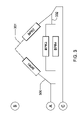
- FIG. 3 is a schematic of one embodiment of three-phase AC source connections of four bulk power regulators (BPRs) of a bulk power assembly such as depicted in FIG. 2 , in accordance with an aspect of the present invention
- FIG. 4 is a graph of phase current drawn on a three-phase AC source versus current provided by a bulk power assembly (such as depicted in FIG. 2 ) without phase balancing control, in accordance with an aspect of the present invention
- FIG. 5 is a graph of phase current drawn on a three-phase AC source versus current provided by a bulk power assembly (such as depicted in FIG. 2 ) with phase balancing control, in accordance with an aspect of the present invention
- FIG. 6 depicts one embodiment of a bulk power regulator with power load adjust circuitry, in accordance with an aspect of the present invention
- FIG. 7 is a flowchart of one embodiment of logic for a frame controller controlling a bulk power assembly of an AC-to-DC power supply assembly, in accordance with an aspect of the present invention
- FIG. 8 is a cross-sectional plan view of one embodiment of an electronics rack with an AC-to-DC power supply assembly comprising redundant bulk power assemblies (BPAs) for supplying power to the electronics subsystem(s) of the electronics rack, and which is controlled in accordance with an aspect of the present invention
- FIG. 9 depicts one embodiment of a computer program product or article of manufacture incorporating one or more aspects of the present invention.
- the term “electronics rack” includes any housing, frame, rack, compartment, blade server system, etc., having one or more components of a data processing system or electronics system, and may be, for example, a stand alone computer processing system having high, mid or low end processing capability.
- An electronics rack comprises at least one electronics subsystem.
- “Electronics subsystem” refers to any sub-housing, blade, book, drawer, node, compartment, etc., having one or more electronic components disposed therein.
- Each electronics subsystem of an electronics rack may be movable or fixed relative to the rack unit, with the electronics drawers of a multi-drawer rack unit and blades of a blade center system being two examples of electronics subsystems of an electronics rack.
- FIG. 1 is an elevational representation of one embodiment of an electronics rack 100 with an AC-to-DC power supply assembly, in accordance with an aspect of the present invention.
- Electronics rack 100 includes a plurality of electronics subsystems 101 , which (in the embodiment illustrated), are air-cooled by cool air 102 ingressing via louvered air inlet door 110 , and exhausting out louvered air outlet door 111 as hot air 103 .
- Electronics rack 100 also includes at least one bulk power assembly 104 of the AC-to-DC power supply assembly.
- AC-to-DC power supply assembly further includes, in one embodiment, a frame controller, which may be resident in the bulk power assembly 104 and/or in one or more electronic subsystems 101 .
- Each electronic subsystem 101 includes, in one example, one or more processors and associated memory. Also illustrated in FIG. 1 is one or more input/output (I/O) drawer(s) 105 , which may also include a switch network. I/O drawer(s) 105 include, for example, PCI card slots and disk drivers for the electronics rack.
- I/O drawer(s) 105 include, for example, PCI card slots and disk drivers for the electronics rack.
- a three-phase AC source feeds power via an AC power supply line cord 106 to bulk power assembly 104 , which transforms the supplied AC power to an appropriate DC power level for output via distribution cable 107 to the plurality of electronics subsystems 101 and I/O drawer(s) 105 .
- AC power supply line cord 106 supplies, in one example, three phases for international 415 V RMS , and has a current limit rating, for example, of 100 amps.
- the number of electronic subsystems installed in the electronics rack is variable and depends on customer requirements for a particular system.
- the number of bulk power regulators within each bulk power assembly of the AC-to-DC power supply assembly is also variable and is determined, in one implementation, by the number of electronic subsystems installed in the electronics rack, or more particularly, by the power requirements of the common load of the electronics rack being fed by the AC-to-DC power supply assembly.
- each single-phase bulk power regulator may provide an 8.8 kW power capability to the common load. If the common load, comprising the electronic subsystem(s), requires more than 24 kW, then a fourth BPR may need to be added to the bulk power assembly. This fourth BPR can be added in parallel to one of the BPRs connected across a phase of the three-phase AC source, such that two BPRs share a common phase of the AC source. Further, assume that the AC power supply line cord has a current limit rating of 100 amps, which limits the input power to 88 amps per phase (0.8 ⁇ 100 A+10%). Thus, the addition of a fourth BPR results in unbalanced phase currents. That is, at 24 kW, phase currents to the four BPRs in the bulk power assembly would be 88 amp, 88 amp, and 63 amp at the 100 amp line cord limit.
- FIG. 2 illustrates one example of an AC-to-DC power supply assembly 200 comprising a frame controller 201 and a bulk power assembly 104 , which in this example comprises four single-phase bulk power regulators 220 (labeled BPR 1 , BPR 2 , BPR 3 & BPR 4 ).
- a serial communications bus 210 allows communication between frame controller 201 and bulk power regulators 220 of bulk power assembly 104 .
- the three-phase AC source is input 106 to bulk power assembly 104 , and bulk power assembly 104 outputs 107 DC power to a common load. In one typical electronics rack example, 350 volts DC power is output to the common load of the rack from the bulk power assembly.
- BPR 1 is connected 300 across phase AB of the three-phase AC source
- BPR 2 is connected 301 across phase BC of the three-phase AC source
- BPR 3 and BPR 4 are connected 302 in parallel across a common phase AC of the three-phase AC source.
- the fourth single-phase bulk power regulator may be needed in order to provide further DC output power to the common load, for example, if the common load passes the 25 kW level in the example described above.
- more than four bulk power regulators may be employed, for example, by coupling an additional BPR across one or both of phases AB and BC, and further coupling additional bulk power regulators across phase AC in FIG. 3 .
- FIG. 4 The result of adding a fourth (or more) bulk power regulator to a bulk power assembly being powered by a three-phase AC source is illustrated in FIG. 4 , wherein the current drawn on the three phases of the three-phase AC source is plotted against the total bulk current output from the bulk power assembly.
- line cord imbalances increase as the total bulk current output increases. The imbalance is the result of the two bulk power regulators in parallel pulling power from the same phase.
- FIG. 5 depicts an alternative plot of phase current versus total bulk current supplied pursuant to a control protocol, in accordance with an aspect of the present invention.
- a line balance mode is employed wherein current drawn on each of the three phases is maintained in balance (notwithstanding the presence of greater than three single-phase power regulators), until the total bulk current supplied reaches a predefined threshold.
- the predefined threshold is selected as a function of the current limit rating of the three-phase AC source feeding the bulk power assembly.
- the threshold is 67.7 amps for the 100 amp line source and bulk power regulators described above.
- the power assembly enters a maximize power mode, wherein the phase currents provided from the three-phase AC source are no longer maintained in balance (and thus diverge slightly), but overall power output from the bulk power assembly is increased, as illustrated in FIG. 5 .
- the AC-to-DC power supply assembly operates in either a line balance mode or a maximize power mode.
- the assembly operates in the line balance mode when the summed current output by the bulk power regulators is below a predefined threshold, and operates in the maximize power mode when the summed current is above the predefined threshold.
- the threshold in one embodiment, is a function of the current limit rating for the line cord providing power from the three-phase AC source.
- the AC-to-DC power supply assembly is maintained in the line balance mode, and if greater power is required by the common load, then the frame controller switches to the maximize power mode, wherein line balancing is no longer achieved, but additional power (above the predefined current threshold) is provided to the common load.
- This multi-mode control approach of the bulk power assembly can be employed with four or more active, single-phase power regulators feeding a common load and powered by a common three-phase AC source. The need for proactive balancing and switching between modes is obviated if the number of bulk power regulators is a multiple of three, since by definition, an even number of bulk power regulators connected per phase inherently results in balanced drawing of phase current.
- control approach described herein is implemented as a software (or logic) solution that allows, for example, system configurations with four BPRs to be shipped without a redesign of the bulk power assembly to enforce AC input current sharing in hardware. It can be shown that adding a fourth BPR without phase balancing (i.e., that is, without digital to analog converter adjustment as described below) will not result in increased bulk power assembly output since the addition of the fourth BPR results in unbalanced phase currents, and a line cord limit with a reduced current on the shared phase.
- the control logic described herein can operate to, for example, control voltage output of the two BPRs not sharing a common phase, or to control voltage output of the two BPRs sharing a common phase.
- FIG. 6 depicts one embodiment of a bulk power regulator (BPR) with load adjust, in accordance with an aspect of the present invention.
- bulk power regulator 220 includes an AC-to-DC converter 600 which receives as input one phase of a three-phase AC source (for example, in the range of 220-480 volts AC). Output from AC-to-DC converter 600 is, in one example, 410 volts DC, which is fed to a DC-to-DC converter 610 .
- DC-to-DC converter comprises IGBT switching devices and is configured to step down the supplied voltage from 410 volts DC to 350 volts DC for output to the common load.
- the BPR further comprises BPR load adjust circuitry, which includes a BPR microprocessor 620 coupled via the serial communications 210 with the frame controller.
- BPR microprocessor 620 outputs, for example, a 16 bit pulse width modulated (PWM) offset signal to a low pass filter 630 .
- Low pass filter 630 outputs a ⁇ 30% signal to an error amp 640 , which also receives as input the analog value of the output voltage 612 .
- Error amp 640 provides a 0 to 3 volt signal to a pulse width modulator (PWM) controller 650 , which is coupled to a gate drive 660 .
- Gate drive 660 provides a gate drive signal 613 to appropriately adjust the current output from DC-to-DC converter 610 .
- the current provided by DC-to-DC converter 610 is also sensed and returned via line 611 to BPR microprocessor 620 for return back to the frame controller, as described further below.
- the signal I_BPR is a signal representative of the amount of current currently being fed into the common load from this particular BPR. Note that in FIG. 6 , the offset signal to adjust the DC/DC converter is being provided by the frame controller to the BPR microprocessor 620 .
- FIG. 7 is a flowchart of one embodiment of frame controller logic for operating the AC-to-DC power supply assembly in either the line balance mode or the maximize power load, dependent upon current being supplied by the bulk power assembly.
- the logic begins 700 with a determination of whether there are greater than three active, single-phase power regulators being powered by a common three-phase AC source and feeding a common load 710 . If “no”, then the frame controller writes a PWM offset of zero to all BPRs of the bulk power assembly 720 . A PWM offset of zero, which is sent via the serial interface 210 ( FIG. 6 ) to each BPR microprocessor, results in a zero load adjustment being applied to each BPR. The logic then waits a period of time (for example, 15 seconds) 730 , before repeating the determination of whether there are currently greater than three active, single-phase power regulators in the AC-to-DC power supply assembly feeding the load.
- a period of time for example, 15 seconds
- the logic reads the actual BPR current output from each of the BPRs using the serial interface coupling the frame controller to each BPR microprocessor (see FIG. 6 ).
- the values reported by the BPRs are measured in amperes, and are sensed at the DC-to-DC converter of each BPR 740 .
- the frame controller sums the currents from the BPRs 750 , and this value (I_BPA) represents the total output current of the bulk power assembly to the common load.
- the total output current value is proportional to the input AC current from the three-phase AC source.
- a threshold value (for example, 67.7 amps in the 100 amp AC source embodiment described above) is predefined to represent the point at which the AC input current would exceed the capability of the line cord. Below this point, phase currents are maintained in balance, while above this point, phase currents are allowed to become unbalanced, but only slightly, as illustrated in FIG. 5 .
- the logic determines whether the I_BPA value is below the predefined threshold (e.g., 67.7 in the 100 amp example described above) 760 . If so, then the logic balances the phases equally by writing 1.28532 ⁇ I_BPA to the BPR's output offset register located in the BPR microprocessor of at least two of the BPRs. In the example illustrated, only the two BPRs not in parallel have their output offsets modified, that is, BPR 1 and BPR 2 in the example of FIGS. 2 & 3 770 .
- 67.7 is the predefined threshold number, which a function of the current limit rating of the three-phase AC source, that is, 100 amps (by way of example). When this limit is exceeded, line cord balancing can no longer be maintained, and maximize power mode is entered.
- the value 1.8532 is ascertained by determining the change in voltage to be achieved by writing a value to the DC/DC converter of the BPR. For example, if two BPRs are connected in parallel across a common phase, then the change in voltage is such that the current through one of the BPRs not connected in parallel is equal to twice the current through the BPRs connected in parallel. This achieves an equal current in the four BPRs.
- the desired change in voltage for a four BPR example is equal to the BPR's output impedance divided by six (since two BPRs are in parallel across a common phase).
- output impedance of a BPR might be 0.475 ohms.
- the total change in voltage is approximately 79.17 milliohms times the I_BPA. If 60 millivolts change per bit is desired, then 79.17 divided by 60 mV per bit equals a DC/DC adjustment of 1.28532 ⁇ I_BPA.
- the logic By adjusting two or more BPRs in the line balance mode, the logic causes the adjusted BPRs' output voltage to rise and additional current to be drawn on the effected phases by the microprocessors changing the duty cycle of their built-in PWM. This results in a higher output voltage at the low pass filter, and when the error amp detects the new voltage and the desired output, it increases the signal to the pulse width modulator. The change at the pulse width modulator causes the gate drive to raise the output voltage. Based on the output resistance (load line), the individual BPR's output current will no longer be equal, but the phase current on the AC input line will be equal.
- the logic of FIG. 7 if above the predefined threshold (for example, the 67.7 amp limit described above) AC phases are balanced to the greatest extent possible, while maximizing BPR output power. This is achieved by writing, for example, an output offset value (0x67) to the two BPRs that are not in parallel using the above-outlined steps 780 . After adjusting the PWM offset, the logic waits a predefined interval 730 before repeating the process.
- the predefined threshold for example, the 67.7 amp limit described above
- FIG. 8 depicts a further control enhancement which may be employed in combination with or separate from the above-described control of the AC-to-DC power supply assembly.
- FIG. 8 a cross-sectional plan view of an electronics rack 800 is illustrated, taken through the AC-to-DC power supply assembly, for example, disposed at the upper portion of the electronics rack.
- the AC-to-DC power supply assembly comprises a first, front bulk power assembly 804 and a second, back bulk power assembly 804 ′.
- bulk power assembly 804 comprises six bulk power regulators, with regulators BPR 1 -BPR 3 806 being powered by a first three-phase AC source 808 and regulators BPR 4 -BPR 6 807 being powered by a second, independent three-phase AC source 809 .
- the second, back bulk power assembly 804 ′ comprises six bulk power regulators, with regulators BPR 1 -BPR 3 806 ′ powered (in the depicted example) by the first three-phase AC source 808 , and regulators BPR 4 -BPR 6 807 ′ powered by the second three-phase AC source 809 .
- second, back bulk power assembly 804 ′ may be powered by three-phase AC sources which are independent from the three-phase AC sources powering the first, front bulk power assembly 804 .
- each bulk power assembly may have its regulators powered by a common three-phase AC source, with the common three-phase AC source being different between bulk power assemblies.
- Cooling is provided to bulk power assemblies 804 , 804 ′ via airflow from a front side to a back side of the electronics rack 800 .
- this airflow is facilitated by a front bulk power fan (BPF) 810 associated with bulk power assembly 804 and a back bulk power fan (BPF) 810 ′ associated with bulk power assembly 804 ′.
- Inlet air 802 is directed in a sinusoidal manner across the bulk power regulators of the bulk power assemblies 804 , 804 ′ by the active drawing of air through bulk power fans 810 , 810 ′, with the heated air egressing out the back side of electronics rack 800 as exhaust air 803 .
- a control protocol which includes automatically reducing the common load power requirements, that is, the power required by the electronics subsystem(s) within the electronics rack, when the bulk power assembly capacity is exceeded for any one of the following atypical conditions: failure of a bulk power fan, such as the front bulk power fan 801 in FIG. 8 ; loss of an AC line cord feeding three of the 12 BPRs illustrated in FIG. 8 ; existence of ambient room conditions out of specification (e.g., >35° C. ambient temperature); or an airflow anomaly within one or both of the BPAs 804 , 804 ′.
- the frame controller can immediately reduce power consumption by requesting a low power (or power save) mode for each electronic subsystem within the electronics rack.
- the affected BPA power output is shifted to the cooler BPA of the two BPAs of the AC-to-DC power supply assembly.
- the BPA power can be shifted from the hot BPA (e.g., >95° C.). to the cooler BPA (e.g., ⁇ 85° C.) by lowering the DC/DC converter settings for all the BPRs on the hot BPA by, for example, approximately four volts.
- the shifting of power load from the front BPA to the back BPA could again be accomplished by raising the DC/DC converter settings of the BPRs in the front bulk power assembly 804 . This results in a greater power load being shifted to the back BPA, which is better able to handle the load due to the better cooling of that assembly by the operation of its bulk power fan 810 ′.
- one or more aspects of the present invention can be included in an article of manufacture (e.g., one or more computer program products) having, for instance, computer usable media.
- the media has therein, for instance, computer readable program code means or logic (e.g., instructions, code, commands, etc.) to provide and facilitate the capabilities of the present invention.
- the article of manufacture can be included as a part of a computer system or sold separately.
- a computer program product 900 includes, for instance, one or more computer-readable media 910 to store computer readable program code means or logic 920 thereon to provide and facilitate one or more aspects of the present invention.
- the medium can be an electronic, magnetic, optical, electromagnetic, infrared, or semiconductor system (or apparatus or device) or a propagation medium.
- Examples of a computer readable medium include a semiconductor or solid state memory, magnetic tape, a removable computer diskette, a random access memory (RAM), a read-only memory (ROM), a rigid magnetic disk and an optical disk.
- Examples of optical disks include compact disk-read only memory (CD-ROM), compact disk-read/write (CD-R/W) and DVD.
- a sequence of program instructions or a logical assembly of one or more interrelated modules defined by one or more computer readable program code means or logic direct the performance of one or more aspects of the present invention.
- a data processing system suitable for storing and/or executing program code includes at least one processor coupled directly or indirectly to memory elements through a system bus.
- the memory elements include, for instance, local memory employed during actual execution of the program code, bulk storage, and cache memory which provide temporary storage of at least some program code in order to reduce the number of times code must be retrieved from bulk storage during execution.
- I/O devices can be coupled to the system either directly or through intervening I/O controllers.
- Network adapters may also be coupled to the system to enable the data processing system to become coupled to other data processing systems or remote printers or storage devices through intervening private or public networks. Modems, cable modems, and Ethernet cards are just a few of the available types of network adapters.
- the capabilities of one or more aspects of the present invention can be implemented in software, firmware, hardware, or some combination thereof.
- At least one program storage device readable by a machine embodying at least one program of instructions executable by the machine to perform the capabilities of the present invention can be provided.
Abstract
Description
Claims (20)
Priority Applications (1)
| Application Number | Priority Date | Filing Date | Title |
|---|---|---|---|
| US12/361,639 US7715215B1 (en) | 2009-01-29 | 2009-01-29 | Control of an AC-to-DC power supply assembly fed by a three-phase AC source |
Applications Claiming Priority (1)
| Application Number | Priority Date | Filing Date | Title |
|---|---|---|---|
| US12/361,639 US7715215B1 (en) | 2009-01-29 | 2009-01-29 | Control of an AC-to-DC power supply assembly fed by a three-phase AC source |
Publications (1)
| Publication Number | Publication Date |
|---|---|
| US7715215B1 true US7715215B1 (en) | 2010-05-11 |
Family
ID=42139354
Family Applications (1)
| Application Number | Title | Priority Date | Filing Date |
|---|---|---|---|
| US12/361,639 Active US7715215B1 (en) | 2009-01-29 | 2009-01-29 | Control of an AC-to-DC power supply assembly fed by a three-phase AC source |
Country Status (1)
| Country | Link |
|---|---|
| US (1) | US7715215B1 (en) |
Cited By (10)
| Publication number | Priority date | Publication date | Assignee | Title |
|---|---|---|---|---|
| US20110235379A1 (en) * | 2010-03-24 | 2011-09-29 | Kasemsan Siri | Current sharing power system |
| US20110302429A1 (en) * | 2010-06-08 | 2011-12-08 | Quanta Computer Inc. | Server rack system |
| CN103178598A (en) * | 2011-12-22 | 2013-06-26 | 雅达电子国际有限公司 | Single phase redundant power supply systems for reducing phase current imbalances |
| CN104052074A (en) * | 2013-03-14 | 2014-09-17 | 雅达电子国际有限公司 | Reducing phase current imbalances in single phase redundant power supply systems with unbalanced loads |
| US9166410B1 (en) | 2012-03-14 | 2015-10-20 | Google Inc. | Line balancing for a three-phase alternating current system |
| US9225202B1 (en) | 2012-05-03 | 2015-12-29 | Google Inc. | AC power control for a power supply system during AC line disturbance |
| US9515520B1 (en) | 2012-08-03 | 2016-12-06 | Google Inc. | Battery backup based on voltage feed-forward control in a power supply |
| US9739685B2 (en) | 2014-04-15 | 2017-08-22 | International Business Machines Corporation | Integrated, predictive vibration analysis of rotational machine within electronics rack |
| EP3623904A1 (en) * | 2018-09-12 | 2020-03-18 | Quanta Computer Inc. | Method and system for current sharing balance in three-phase input source system |
| RU2766417C1 (en) * | 2020-03-31 | 2022-03-15 | Гига-Байт Текнолоджи Ко., Лтд. | Power supply control system and method for power supply control |
Citations (7)
| Publication number | Priority date | Publication date | Assignee | Title |
|---|---|---|---|---|
| US20020129009A1 (en) | 2001-03-12 | 2002-09-12 | Affymetrix, Inc. | System, method, and user interfaces for mining of genomic data |
| US6700343B2 (en) * | 2001-07-24 | 2004-03-02 | Hitachi, Ltd. | Motor controller |
| US6801382B2 (en) * | 2001-05-31 | 2004-10-05 | Renesas Technology Corp. | Magnetic disk storage apparatus |
| USRE38846E1 (en) * | 1999-09-01 | 2005-10-25 | Intersil Communications, Inc. | Multi-phase converter with balanced currents |
| US7106017B2 (en) * | 2001-02-14 | 2006-09-12 | Mitsubishi Denki Kabushiki Kaisha | Motor control device |
| US7219258B2 (en) | 2003-12-10 | 2007-05-15 | International Business Machines Corporation | Method, system, and product for utilizing a power subsystem to diagnose and recover from errors |
| US7492134B2 (en) * | 2004-07-02 | 2009-02-17 | Primarion, Inc. | Multiphase power regulator with load adaptive phase control |
-
2009
- 2009-01-29 US US12/361,639 patent/US7715215B1/en active Active
Patent Citations (7)
| Publication number | Priority date | Publication date | Assignee | Title |
|---|---|---|---|---|
| USRE38846E1 (en) * | 1999-09-01 | 2005-10-25 | Intersil Communications, Inc. | Multi-phase converter with balanced currents |
| US7106017B2 (en) * | 2001-02-14 | 2006-09-12 | Mitsubishi Denki Kabushiki Kaisha | Motor control device |
| US20020129009A1 (en) | 2001-03-12 | 2002-09-12 | Affymetrix, Inc. | System, method, and user interfaces for mining of genomic data |
| US6801382B2 (en) * | 2001-05-31 | 2004-10-05 | Renesas Technology Corp. | Magnetic disk storage apparatus |
| US6700343B2 (en) * | 2001-07-24 | 2004-03-02 | Hitachi, Ltd. | Motor controller |
| US7219258B2 (en) | 2003-12-10 | 2007-05-15 | International Business Machines Corporation | Method, system, and product for utilizing a power subsystem to diagnose and recover from errors |
| US7492134B2 (en) * | 2004-07-02 | 2009-02-17 | Primarion, Inc. | Multiphase power regulator with load adaptive phase control |
Non-Patent Citations (2)
| Title |
|---|
| Broyles et al., "Improving Processor Performance During Power Supply Failure", U.S. Appl. No. 12/241,134, filed Sep. 30, 2008. |
| Corrado et al., "Method and System for Automated Energy Usage Monitoring Within a Data Center", U.S. Appl. No. 11/956,405, filed Dec. 14, 2007. |
Cited By (22)
| Publication number | Priority date | Publication date | Assignee | Title |
|---|---|---|---|---|
| US20110235379A1 (en) * | 2010-03-24 | 2011-09-29 | Kasemsan Siri | Current sharing power system |
| US8351229B2 (en) * | 2010-03-24 | 2013-01-08 | The Aerospace Corporation | Current sharing power system |
| US20110302429A1 (en) * | 2010-06-08 | 2011-12-08 | Quanta Computer Inc. | Server rack system |
| US9207734B2 (en) * | 2010-06-08 | 2015-12-08 | Quanta Computer Inc. | Server rack system |
| US20130162042A1 (en) * | 2011-12-22 | 2013-06-27 | Vijay Gangadhar Phadke | Single phase redundant power supplies for reducing phase current imbalances |
| US9891679B2 (en) * | 2011-12-22 | 2018-02-13 | Astec International Limited | Single phase redundant power supply systems for reducing phase current imbalances |
| US20130163297A1 (en) * | 2011-12-22 | 2013-06-27 | Vijay Gangadhar Phadke | Single phase redundant power supply systems for reducing phase current imbalances |
| US9189040B2 (en) * | 2011-12-22 | 2015-11-17 | Astec International Limited | Single phase redundant power supplies for reducing phase current imbalances |
| CN103178598A (en) * | 2011-12-22 | 2013-06-26 | 雅达电子国际有限公司 | Single phase redundant power supply systems for reducing phase current imbalances |
| US9166410B1 (en) | 2012-03-14 | 2015-10-20 | Google Inc. | Line balancing for a three-phase alternating current system |
| US9225202B1 (en) | 2012-05-03 | 2015-12-29 | Google Inc. | AC power control for a power supply system during AC line disturbance |
| US9515520B1 (en) | 2012-08-03 | 2016-12-06 | Google Inc. | Battery backup based on voltage feed-forward control in a power supply |
| US9712080B2 (en) * | 2013-03-14 | 2017-07-18 | Astec International Limited | Reducing phase current imbalances in single phase redundant power supply systems with unbalanced loads |
| US20140268947A1 (en) * | 2013-03-14 | 2014-09-18 | Astec International Limited | Reducing Phase Current Imbalances In Single Phase Redundant Power Supply Systems With Unbalanced Loads |
| CN104052074A (en) * | 2013-03-14 | 2014-09-17 | 雅达电子国际有限公司 | Reducing phase current imbalances in single phase redundant power supply systems with unbalanced loads |
| CN104052074B (en) * | 2013-03-14 | 2018-11-27 | 雅达电子国际有限公司 | It is unbalance that phase current is reduced in the single-phase redundancy electric power supply system with unbalance load |
| US9739685B2 (en) | 2014-04-15 | 2017-08-22 | International Business Machines Corporation | Integrated, predictive vibration analysis of rotational machine within electronics rack |
| US9915584B2 (en) | 2014-04-15 | 2018-03-13 | International Business Machines Corporation | Integrated, predictive vibration analysis of rotational machine within electronics rack |
| EP3623904A1 (en) * | 2018-09-12 | 2020-03-18 | Quanta Computer Inc. | Method and system for current sharing balance in three-phase input source system |
| RU2766417C1 (en) * | 2020-03-31 | 2022-03-15 | Гига-Байт Текнолоджи Ко., Лтд. | Power supply control system and method for power supply control |
| RU2766417C9 (en) * | 2020-03-31 | 2022-03-25 | Гига-Байт Текнолоджи Ко., Лтд. | Power supply control system and method for power supply control |
| US11307643B2 (en) | 2020-03-31 | 2022-04-19 | Giga-Byte Technology Co., Ltd. | Power management system and power management method for computer system |
Similar Documents
| Publication | Publication Date | Title |
|---|---|---|
| US7715215B1 (en) | Control of an AC-to-DC power supply assembly fed by a three-phase AC source | |
| US9000707B2 (en) | Use of cooling fan in adjustable speed drives | |
| EP2071699B1 (en) | Battery load allocation in parallel-connected uninterruptible power supply systems | |
| US20150309522A1 (en) | Control Method and Apparatus | |
| US20150305197A1 (en) | Equipment enclosure fan control systems and methods | |
| US20120017104A1 (en) | Computer and power management system for computer | |
| JPH10201090A (en) | Power unit | |
| KR102342101B1 (en) | uninterruptible power system | |
| US20140132070A1 (en) | Rack and power control method thereof | |
| JP5997700B2 (en) | Power supply device and control method thereof | |
| US20200081504A1 (en) | Method and system for current sharing balance in three-phase input source system | |
| US20100264733A1 (en) | Bulk power assembly | |
| US10942555B2 (en) | Power supplying method for computer system | |
| EP2740201B1 (en) | A controller for a voltage converter | |
| US11224141B2 (en) | Server rack system and method of power management in the server rack system | |
| JP6924806B2 (en) | Methods and systems to compensate for the effects of elevated temperatures | |
| EP2366134B1 (en) | Power conversion, control, and distribution system | |
| US7312962B1 (en) | Intelligent overcurrent protection for power supplies | |
| US8281172B2 (en) | Server with multiple power supplies transitioning first power supply from its online state to its standby state and second power supply to its deep-sleep state | |
| US20140016259A1 (en) | Multi-motherboard power data communication architecture for power supplies | |
| JP2020140378A (en) | Power supply circuit and electronic apparatus | |
| US11108266B2 (en) | Control method for power supply system and power supply system | |
| Rasmussen | Eco-mode: Benefits and risks of energy-saving modes of UPS operation | |
| CN109962634B (en) | Inverter control method, inverter control device, and electronic apparatus | |
| CN114637357B (en) | Fault detection method, controller, bypass voltage stabilizing circuit and storage medium |
Legal Events
| Date | Code | Title | Description |
|---|---|---|---|
| AS | Assignment |
Owner name: INTERNATIONAL BUSINESS MACHINES CORPORATION,NEW YO Free format text: ASSIGNMENT OF ASSIGNORS INTEREST;ASSIGNORS:BOSCO, FRANK E.;COVI, KEVIN R.;COZZOLINO, ANTHONY J.;AND OTHERS;REEL/FRAME:022171/0704 Effective date: 20090127 |
|
| FEPP | Fee payment procedure |
Free format text: PAYOR NUMBER ASSIGNED (ORIGINAL EVENT CODE: ASPN); ENTITY STATUS OF PATENT OWNER: LARGE ENTITY |
|
| STCF | Information on status: patent grant |
Free format text: PATENTED CASE |
|
| REMI | Maintenance fee reminder mailed | ||
| AS | Assignment |
Owner name: TWITTER, INC., CALIFORNIA Free format text: ASSIGNMENT OF ASSIGNORS INTEREST;ASSIGNOR:INTERNATIONAL BUSINESS MACHINES CORPORATION;REEL/FRAME:032075/0404 Effective date: 20131230 |
|
| FPAY | Fee payment |
Year of fee payment: 4 |
|
| SULP | Surcharge for late payment | ||
| FEPP | Fee payment procedure |
Free format text: MAINTENANCE FEE REMINDER MAILED (ORIGINAL EVENT CODE: REM.) |
|
| FEPP | Fee payment procedure |
Free format text: 7.5 YR SURCHARGE - LATE PMT W/IN 6 MO, LARGE ENTITY (ORIGINAL EVENT CODE: M1555) |
|
| MAFP | Maintenance fee payment |
Free format text: PAYMENT OF MAINTENANCE FEE, 8TH YEAR, LARGE ENTITY (ORIGINAL EVENT CODE: M1552) Year of fee payment: 8 |
|
| MAFP | Maintenance fee payment |
Free format text: PAYMENT OF MAINTENANCE FEE, 12TH YEAR, LARGE ENTITY (ORIGINAL EVENT CODE: M1553); ENTITY STATUS OF PATENT OWNER: LARGE ENTITY Year of fee payment: 12 |
|
| AS | Assignment |
Owner name: MORGAN STANLEY SENIOR FUNDING, INC., MARYLAND Free format text: SECURITY INTEREST;ASSIGNOR:TWITTER, INC.;REEL/FRAME:062079/0677 Effective date: 20221027 Owner name: MORGAN STANLEY SENIOR FUNDING, INC., MARYLAND Free format text: SECURITY INTEREST;ASSIGNOR:TWITTER, INC.;REEL/FRAME:061804/0086 Effective date: 20221027 Owner name: MORGAN STANLEY SENIOR FUNDING, INC., MARYLAND Free format text: SECURITY INTEREST;ASSIGNOR:TWITTER, INC.;REEL/FRAME:061804/0001 Effective date: 20221027 |