US7712901B2 - Method and apparatus for diagnosing conditions of the eye with infrared light - Google Patents
Method and apparatus for diagnosing conditions of the eye with infrared light Download PDFInfo
- Publication number
- US7712901B2 US7712901B2 US11/999,529 US99952907A US7712901B2 US 7712901 B2 US7712901 B2 US 7712901B2 US 99952907 A US99952907 A US 99952907A US 7712901 B2 US7712901 B2 US 7712901B2
- Authority
- US
- United States
- Prior art keywords
- light
- eye
- infrared
- iris
- digital image
- Prior art date
- Legal status (The legal status is an assumption and is not a legal conclusion. Google has not performed a legal analysis and makes no representation as to the accuracy of the status listed.)
- Expired - Fee Related
Links
- 238000000034 method Methods 0.000 title claims abstract description 52
- 208000037265 diseases, disorders, signs and symptoms Diseases 0.000 claims abstract description 15
- 201000010099 disease Diseases 0.000 claims abstract description 12
- 230000003595 spectral effect Effects 0.000 claims description 30
- 201000000041 pigment dispersion syndrome Diseases 0.000 claims description 27
- 238000001228 spectrum Methods 0.000 claims description 14
- 208000031513 cyst Diseases 0.000 claims description 8
- 208000030533 eye disease Diseases 0.000 claims description 5
- 239000007943 implant Substances 0.000 claims description 5
- 208000014674 injury Diseases 0.000 claims description 5
- 230000008733 trauma Effects 0.000 claims description 5
- 238000002059 diagnostic imaging Methods 0.000 claims description 4
- 206010001557 Albinism Diseases 0.000 claims description 3
- 206010022941 Iridocyclitis Diseases 0.000 claims description 3
- 241000282485 Vulpes vulpes Species 0.000 claims description 3
- 201000004612 anterior uveitis Diseases 0.000 claims description 3
- 201000004949 exfoliation syndrome Diseases 0.000 claims description 3
- 230000000149 penetrating effect Effects 0.000 claims 5
- 238000007599 discharging Methods 0.000 claims 2
- 230000003213 activating effect Effects 0.000 claims 1
- 238000003384 imaging method Methods 0.000 abstract description 27
- 238000005286 illumination Methods 0.000 abstract description 10
- 238000004458 analytical method Methods 0.000 abstract description 7
- 238000001514 detection method Methods 0.000 description 13
- 230000007547 defect Effects 0.000 description 9
- 239000000523 sample Substances 0.000 description 9
- 238000012360 testing method Methods 0.000 description 8
- 239000013598 vector Substances 0.000 description 7
- 208000010412 Glaucoma Diseases 0.000 description 6
- 210000000744 eyelid Anatomy 0.000 description 6
- 239000000049 pigment Substances 0.000 description 5
- 230000000007 visual effect Effects 0.000 description 5
- 239000008187 granular material Substances 0.000 description 4
- 230000035945 sensitivity Effects 0.000 description 4
- 238000007619 statistical method Methods 0.000 description 4
- 206010061818 Disease progression Diseases 0.000 description 3
- 230000008901 benefit Effects 0.000 description 3
- 238000000701 chemical imaging Methods 0.000 description 3
- 230000005750 disease progression Effects 0.000 description 3
- 208000035475 disorder Diseases 0.000 description 3
- 210000003128 head Anatomy 0.000 description 3
- 210000001747 pupil Anatomy 0.000 description 3
- 238000011160 research Methods 0.000 description 3
- 210000001519 tissue Anatomy 0.000 description 3
- 235000001543 Corylus americana Nutrition 0.000 description 2
- 240000007582 Corylus avellana Species 0.000 description 2
- 235000007466 Corylus avellana Nutrition 0.000 description 2
- 206010030348 Open-Angle Glaucoma Diseases 0.000 description 2
- 206010035015 Pigmentary glaucoma Diseases 0.000 description 2
- 208000012641 Pigmentation disease Diseases 0.000 description 2
- 241000320126 Pseudomugilidae Species 0.000 description 2
- 238000012952 Resampling Methods 0.000 description 2
- 230000002159 abnormal effect Effects 0.000 description 2
- 238000013459 approach Methods 0.000 description 2
- 230000000881 depressing effect Effects 0.000 description 2
- 238000003745 diagnosis Methods 0.000 description 2
- 238000009826 distribution Methods 0.000 description 2
- 238000011156 evaluation Methods 0.000 description 2
- 230000004424 eye movement Effects 0.000 description 2
- 230000003993 interaction Effects 0.000 description 2
- 238000002372 labelling Methods 0.000 description 2
- 239000011159 matrix material Substances 0.000 description 2
- 238000012544 monitoring process Methods 0.000 description 2
- 238000005457 optimization Methods 0.000 description 2
- 230000035515 penetration Effects 0.000 description 2
- 230000008569 process Effects 0.000 description 2
- 210000001585 trabecular meshwork Anatomy 0.000 description 2
- 238000012549 training Methods 0.000 description 2
- 210000000216 zygoma Anatomy 0.000 description 2
- 201000009487 Amblyopia Diseases 0.000 description 1
- 206010003694 Atrophy Diseases 0.000 description 1
- 241000692783 Chylismia claviformis Species 0.000 description 1
- 208000003556 Dry Eye Syndromes Diseases 0.000 description 1
- 206010013774 Dry eye Diseases 0.000 description 1
- LFQSCWFLJHTTHZ-UHFFFAOYSA-N Ethanol Chemical compound CCO LFQSCWFLJHTTHZ-UHFFFAOYSA-N 0.000 description 1
- 206010061218 Inflammation Diseases 0.000 description 1
- 206010022948 Iris atrophy Diseases 0.000 description 1
- 241001085205 Prenanthella exigua Species 0.000 description 1
- KCLANYCVBBTKTO-UHFFFAOYSA-N Proparacaine Chemical compound CCCOC1=CC=C(C(=O)OCCN(CC)CC)C=C1N KCLANYCVBBTKTO-UHFFFAOYSA-N 0.000 description 1
- 230000005856 abnormality Effects 0.000 description 1
- 238000010521 absorption reaction Methods 0.000 description 1
- 230000003044 adaptive effect Effects 0.000 description 1
- 230000002547 anomalous effect Effects 0.000 description 1
- 239000000607 artificial tear Substances 0.000 description 1
- 230000037444 atrophy Effects 0.000 description 1
- 230000009286 beneficial effect Effects 0.000 description 1
- 230000005540 biological transmission Effects 0.000 description 1
- 230000004397 blinking Effects 0.000 description 1
- 239000003086 colorant Substances 0.000 description 1
- 238000004891 communication Methods 0.000 description 1
- 230000006835 compression Effects 0.000 description 1
- 238000007906 compression Methods 0.000 description 1
- 239000012141 concentrate Substances 0.000 description 1
- 238000012790 confirmation Methods 0.000 description 1
- 238000001804 debridement Methods 0.000 description 1
- 230000008021 deposition Effects 0.000 description 1
- 238000002405 diagnostic procedure Methods 0.000 description 1
- 230000000694 effects Effects 0.000 description 1
- 238000005516 engineering process Methods 0.000 description 1
- 238000002474 experimental method Methods 0.000 description 1
- 239000012530 fluid Substances 0.000 description 1
- 229910052736 halogen Inorganic materials 0.000 description 1
- 150000002367 halogens Chemical class 0.000 description 1
- 231100001261 hazardous Toxicity 0.000 description 1
- 238000010191 image analysis Methods 0.000 description 1
- 230000004054 inflammatory process Effects 0.000 description 1
- 239000004615 ingredient Substances 0.000 description 1
- 230000004410 intraocular pressure Effects 0.000 description 1
- 208000028867 ischemia Diseases 0.000 description 1
- 238000010801 machine learning Methods 0.000 description 1
- 230000007246 mechanism Effects 0.000 description 1
- 238000000491 multivariate analysis Methods 0.000 description 1
- 238000003909 pattern recognition Methods 0.000 description 1
- 230000019612 pigmentation Effects 0.000 description 1
- 238000012545 processing Methods 0.000 description 1
- 230000002035 prolonged effect Effects 0.000 description 1
- 229960003981 proparacaine Drugs 0.000 description 1
- 230000009467 reduction Effects 0.000 description 1
- 210000001525 retina Anatomy 0.000 description 1
- 230000004253 retinal exposure Effects 0.000 description 1
- 238000012216 screening Methods 0.000 description 1
- 238000012706 support-vector machine Methods 0.000 description 1
- 238000012546 transfer Methods 0.000 description 1
- 238000000411 transmission spectrum Methods 0.000 description 1
- 238000002604 ultrasonography Methods 0.000 description 1
- 238000012800 visualization Methods 0.000 description 1
Images


Classifications
-
- A—HUMAN NECESSITIES
- A61—MEDICAL OR VETERINARY SCIENCE; HYGIENE
- A61B—DIAGNOSIS; SURGERY; IDENTIFICATION
- A61B3/00—Apparatus for testing the eyes; Instruments for examining the eyes
- A61B3/10—Objective types, i.e. instruments for examining the eyes independent of the patients' perceptions or reactions
- A61B3/12—Objective types, i.e. instruments for examining the eyes independent of the patients' perceptions or reactions for looking at the eye fundus, e.g. ophthalmoscopes
- A61B3/1216—Objective types, i.e. instruments for examining the eyes independent of the patients' perceptions or reactions for looking at the eye fundus, e.g. ophthalmoscopes for diagnostics of the iris
Definitions
- This invention relates generally to a method and apparatus for diagnosing eye conditions or diseases.
- PDS pigment dispersion syndrome
- trabecular meshwork the structure within the eye that permits drainage. Prolonged deposition of pigment granules in this structure may cause a reduction in the ability of the trabecular meshwork to transport fluid from the eye, which can result in an elevation of the intraocular pressure and glaucoma.
- Glaucoma is a frequent complication of the condition, with estimates for the progression from PDS to pigmentary glaucoma ranging as high as 50%. Pigmentary glaucoma is now generally considered as one of the more-common forms of secondary glaucoma.
- iris evaluation has been performed with the room lights turned off and the patient positioned with his or her head in front of a slit lamp biomicroscope, which is an instrument used to examine the eye visually under magnification. With the patient looking straight ahead, a small beam of light is directed into the eye through the pupil. The practitioner then visually evaluates the front side of the iris for penetration of reflected light from inside the eye. Normally the iris is fairly opaque and reflected light will not be observed. However, the diseased iris may be thinned in some areas due to loss of pigment granules or tissue atrophy, and thus may permit light to penetrate.
- a fiber-optic light source is placed against the lower eyelid and directed toward the globe of the eye.
- the practitioner visually examines the front side of the iris for evidence of penetration by internally reflected light.
- This second method suffers from the same limitations as the first method.
- a general object of the invention is to provide an improved method and apparatus for examining and diagnosing conditions of the eye.
- a more specific objective of the invention is to overcome one or more of the problems described above.
- the general object of the invention can be attained, at least in part, through a method of detecting a condition or disease in an eye of a patient.
- the method includes: emitting at least one light beam into the eye through skin directly adjacent to a portion of the eye; digitally capturing a first reflected light spectrum from the eye from the at least one light beam; digitally capturing a second reflected light spectrum from the eye from the at least one light beam; producing a first digital image from the first reflected light spectrum; and producing a second digital image from the second reflected light spectrum.
- the invention further comprehends a method of detecting a condition or disease in an eye of a patient including: emitting infrared light into the eye through skin directly adjacent to a portion of the eye; digitally capturing reflected light from the eye; and producing a digital image of the eye using only the digitally captured infrared light.
- the invention still further comprehends an apparatus for use in diagnostic imaging of an eye.
- the apparatus includes a body and an infrared light source in combination with the body.
- the infrared light source emits one or more spectral ranges of infrared light concentrated around a predetermined infrared wavelength.
- the body including a light discharge end having a size and shape adapted to be placed against skin adjacent to and over a portion of the eye.
- the apparatus of this invention is a new diagnostic imaging device for use by eye care practitioners.
- the apparatus collects and, desirably, automatically analyzes multispectral infrared images (e.g., multiple images, each taken using a different wavelength of light) of the iris (the pigmented structure at the front of the eye), permitting the visualization and automatic detection of iris defects associated with pigment dispersion syndrome (PDS) and other ocular conditions that can lead to glaucoma.
- PDS pigment dispersion syndrome
- the multispectral imaging according to this invention produces useful, quality images in spite of complicating variations in eye and skin pigmentations of patients. Multispectral imaging also permits abnormalities to be detected by virtue of different appearances at different wavelength spectra.
- narrowband near-infrared (NIR) light is directed through the skin above the cheekbone, thus causing the eye to glow from within. Some of this light penetrates the iris from behind, permitting details of iris structures to be imaged. Multiple images can be acquired in rapid succession at different wavelengths across the NIR band. These images will be automatically analyzed by computer to identify abnormal regions, with capabilities for longitudinal monitoring to track disease progression.
- NIR near-infrared
- iris defects show very limited contrast when transilluminating the iris with visible light, these defects are clearly visualized when using NIR light.
- the imaging technique of this invention can readily detect iris defects that are difficult or impossible to observe by visual examination, even in patients with darkly pigmented eyes and/or skin for whom traditional examination techniques perform very poorly.
- the multispectral capability of the apparatus allows adaptive optimization of imaging performance to each subject's pigmentation type, and the spectral signatures within the images can be used to help discriminate defects from normal iris tissue.
- infrared is to be understood to refer to include near infrared wavelengths.
- references herein to “transillumination” are to be understood to refer to the illumination of an object, e.g., an eye, by passing light through it, rather than by reflecting light from its surface.
- FIG. 1 is a digital image detection system for use in the apparatus of one embodiment of this invention.
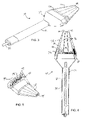
- FIG. 2 is an illumination device according to one embodiment of this invention.
- FIGS. 3-5 illustrate an illumination device according to one embodiment of this invention.
- FIG. 6 shows example images, annotated to highlight PDS defects, of normal and PDS patients imaged according to the method of one embodiment of this invention.
- FIG. 7 is a histogram of the calculated correlation coefficients from the examples below.
- FIG. 8 includes images of the same iris acquired at different wavelengths according to the examples below.
- FIG. 9 is a box-whisker plot summarizing contrast values of the examples below.
- FIG. 10 includes iris images showing iridociliary cysts detected with a method of one embodiment of this invention in normal patients who were unsuspected of having the condition after examination.
- FIG. 11 includes iris images showing conditions detected with a method of one embodiment of this invention in normal patients who were unsuspected of having the condition after examination.
- the present invention provides a method of detecting a condition or disease in an eye.
- the method of this invention utilizes a light source, desirably including infrared (IR) light, and more desirably including narrow-band infrared light (NIR), directed through the skin above the cheekbone. Applied in this manner, the light causes the eye to glow from within. Some of this light is reflected out of the eye and penetrates the iris from behind, permitting details of iris structures to be digitally imaged.
- predetermined wavelengths of light e.g., IR light
- the method of this invention allows for multiple images to be acquired in rapid succession, each image at one of the different wavelengths across, for example, the NIR band. According to one embodiment of this invention, these images will be automatically analyzed by a data processor to identify abnormal regions, with capabilities for longitudinal monitoring to track disease progression.
- the invention also includes an imaging apparatus for assessment of diseases of the iris.
- the apparatus of this invention includes a light source for transillumination of the eye.
- the apparatus of one embodiment of this invention also desirably includes a digital image detector for recording images of the eye when the light source is applied.
- the apparatus of this invention is envisioned to become a standard piece of equipment in eye care practices that concentrates on the management and treatment of glaucoma.
- the apparatus can also be an important research resource that will be used by investigators in university research centers.
- the method and apparatus of this invention can be used to diagnose and analyze eye diseases or eye conditions, such as pigment dispersion syndrome, iridociliary cysts, albinism, trauma, exfoliation syndrome, Fuchs' heterochromic iridocyclitis, and problems caused by intraocular lens implants.
- eye diseases or eye conditions such as pigment dispersion syndrome, iridociliary cysts, albinism, trauma, exfoliation syndrome, Fuchs' heterochromic iridocyclitis, and problems caused by intraocular lens implants.
- FIG. 1 illustrates a digital image detection system 10 for use in the apparatus of this invention.
- Detection system 10 includes a digital image detector 12 for taking a picture of an eye, and more specifically, for digitally capturing light reflected from within the eye, resulting from a transillumination light source applied to the eye.
- the digital image detector 12 can be any digital detector, and is selected based upon its ability to detect and image the type of light reflected from the eye. For example, when infrared light is used as the light source, the digital detector 12 desirably detects infrared light in order to produce digital images, such as in combination with a data processor, using the detected infrared light.
- Various commercial digital cameras for example those modified to remove any IR-blocking filter, could be used as the digital detector 12 , and the detection system 10 can be adapted to secure a digital camera on detector stand 14 by the screw-mount hole commonly found on most cameras.
- the digital image detector 12 is connected to a user interface 20 .
- the user interface 20 includes a view screen 22 for viewing images produced using the digital image detector 12 .
- the view screen 22 includes a touch screen to allow user interaction with the display, and control of at least portions of the system thereby.
- the digital image detector 12 can be connected directly to the user interface 20 , but desirably a data processor, e.g., computer, is used as an intermediary for analyzing and transmitting the images to the view screen 22 .
- the system 10 could exclude the user interface 20 , and be used with a user's existing computer, e.g., a desktop or laptop, whereby the digital images are shown on the associated monitor.
- the system 10 desirably includes a recordable medium for recording and storing the digital images.
- the recordable medium can be included in the detector 12 itself, within the user interface 12 , or with or within a data processor used with the system 10 .
- the detection system 10 further includes a control device 30 which allows the detector 12 to be moved into the proper position once the patient's head is positioned on the adjustable chin/headrest 40 .
- the control device 30 in FIG. 1 includes a joystick 32 for moving the detector 12 into position.
- the joystick 32 allows the camera to be moved freely from side to side, and forward/backward to control the focus and field of view of detector 12 .
- the joystick 32 is connected to a system of gears, such as gear 34 , and other mechanical components, according to known mechanisms, to move the detector into the desired positioning.
- the joystick 32 can include a trigger to activate the detector 12 to capture an image.
- an optional footswitch is provided for triggering the start of image acquisition.
- the footswitch frees the clinician's hands to apply the light source and position the camera.
- an optional fixation/constriction light source 42 can be directed at the eyes and used to help the patient to look forward, and to create consensual papillary constriction in the examined eye so that the iris surface area is maximized.
- FIG. 2 illustrates a transillumination device 50 , according to one embodiment of this invention.
- Device 50 includes a body 52 and a light source 54 .
- the light source 54 can include any desirable light source, and in the embodiment of this invention shown in FIG. 2 , is a narrow band infrared light source.
- LEDs light emitting diodes
- LDs laser diodes
- filtered white light Various sources of narrowband illumination are available for use with the method and apparatus of this invention, such as light emitting diodes (LEDs), laser diodes (LDs), and filtered white light.
- the infrared light source 54 of FIG. 2 includes three light emitting diodes 56 .
- LEDs provide an ideal light source for use in this invention because they offer sufficient power, they are inexpensive, they are totally safe, they can be switched electronically, and they are available in a wide variety of wavelengths, such as 625 nm, 655 nm, 700 nm, 750 nm, 810 nm, 850 nm, 910 nm, 950 nm, 1000 nm, and 1050 nm.
- the light source includes LEDs that each emits only one or more spectral ranges of light concentrated around a predetermined wavelength selected from wavelengths from about 650 nanometers to about 1000 nanometers.
- Exemplary infrared LED wavelengths include 700 nm, 750 nm, 810 nm, 850 nm, 910 nm and 950 nm.
- a LED may emit light concentrated at its identified wavelength, the LED is likely to emit wavelengths in a spectral range near to the identified peak wavelength.
- each of the three LEDs 56 has the same selected wavelength, e.g., 750 nm.
- the transillumination device 50 is desirably controlled by an electronic control module in combination with the data processor, which allows the intensity to be varied or switched individually from a software interface.
- the three LEDs 56 are arranged in a linear fashion at a light discharge end 58 of the body 52 .
- the light discharge end 58 has a size and shape adapted to be placed against skin adjacent to and over a portion of the eye. Desirably, the light discharge end 58 has a shape with a first dimension that is greater than a second dimension, such as rectangular, elliptical, or ovoid.
- the light discharge end 58 is desirably positioned at the anterior of the lower eyelid. The elongated profile of the light discharge end 58 ensures that the clinician holds the probe roughly normal to the globe of the eye, at least with respect to the horizontal plane.
- FIGS. 3-5 illustrate a transillumination device 70 according to another embodiment of this invention.
- the device 70 includes a body 72 .
- the body 72 shown in FIGS. 3-5 includes a handle 74 , an electric socket element 76 and a light focusing element 78 .
- the electric socket element 76 and the light focusing element 78 are attached to the remainder of the body 72 by a bolt or screw 80 .
- a wire 82 connectable to a power source (not shown), extends through the handle 74 and is in electric power supplying connection with the electric socket element 76 .
- the electric socket can be integrally formed with the body, and/or the illustrated elongated handle may be substituted with a wider, or perhaps round, body that can be held in the clinician's hand.
- the device 70 includes a light source, shown in FIG. 4 as a plurality of light emitting diodes 84 , 86 , and 88 .
- the electric socket element 76 includes three plug sets 90 , each plug set 90 including four electric plugs 90 .
- Each electric plug 92 is adapted to receive a light emitting diode, such as one of light emitting diodes 84 , 86 , and 88 .
- each of the light emitting diodes 84 , 86 , and 88 emits only one spectral range of infrared light that is concentrated around a predetermined infrared wavelength.
- diode 84 can be a 700 nm LED
- diode 86 can be a 750 nm LED
- diode 88 can be an 850 nm LED.
- Including LEDs of different wavelengths in device 70 provides for a multispectral device that is able to generate beams of light concentrated around different desired light wavelengths from a single device.
- the multispectral device 70 desirably is coupled with an electronic control module (ECM) to provide maximum flexibility of operation to facilitate exploratory studies and optimization of illumination.
- ECM electronice control module
- the ECM allows LEDs of only one or more wavelengths to operate at one time, based upon control signals from the data processor and/or user.
- the ECM also desirably can adjust the power level of the LEDs individually as well as turning them on or off as desired.
- the light focusing element 78 extends from the socket element 76 to a light discharge end 94 .
- the light focusing element 78 includes three light focusing channels 96 extending therethrough, with each light focusing channel 96 associated with and disposed over one of the LED plug sets 90 . As shown in FIG. 4 , the light focusing element 78 is disposed over the plug sets 90 so that the LEDs are disposed at least partially within the corresponding light focusing channel 96 . Desirably, each light focusing channel includes an LED of each desired light wavelength.
- the light focusing channels 96 are desirably tapered, include a reflective surface, and extend between the light source and the light discharge end, all for focusing the light from the LEDs through a passageway 98 to the light discharge end 94 .
- the light discharge end 94 has a size and shape adapted to be placed against the skin adjacent to and over a portion of the eye.
- various and alternative sizes, shapes, amounts, types, and configurations of the LEDs, the light discharge end, and the light focusing channels are available for this invention.
- the device and method of one embodiment of this invention include and are implemented in part by software that is recorded on a recordable medium and executable on a data processor (e.g., a laptop computer).
- the software controls the operations of the different components of the imaging apparatus of this invention. The entire imaging process can be carried out through interaction with a unified graphical user interface, as discussed above.
- the software provides an interface for controlling the transillumination light source. The user can select the wavelength to use and adjust its power level through the user interface.
- the software also provides a set of default power levels based on the race and iris color of the patient.
- the software further provides an interface for controlling the camera setting: e.g., brightness, contrast, gamma and exposure.
- the software of one embodiment of this invention also provides a set of default camera settings based on the race and iris color of the patient.
- the software provides real-time image display on the user interface or associated computer, which the examiner uses to adjust the focus and field of view of the camera.
- the transillumination images are acquired and recorded by, for example, depressing a footswitch, and the software then displays all acquired images on the screen for visual examination.
- the software also provides an interface for recording relevant subject information and archiving acquired image data. Image filenames are automatically created using the imaging parameters and unique subject identification code. All images are saved on a recordable medium, such as a hard drive or flash drive, in a suitable image format, such as a bitmap format using lossless compression.
- Personal identification information is desirably saved separately and kept confidential.
- the software maintains an image database and provides easy access to archived images. Users can search for a subset of images according to acquisition date, wavelength, patient identification, iris color, race, diagnosis and imaged eye. The list of images satisfying all criteria is desirably shown in a separate window. The user can then view all the images from the list or only selected ones.
- a light beam is emitted into the eye, desirably through skin adjacent to and over a portion of the eye.
- the emitted beam is reflected within the eye and causes the eye to glow from within.
- the reflected light is digitally captured and used to produce a digital image of the eye which can be analyzed by a clinician or automatically by the software described above.
- the above described steps are repeated using light at different wavelengths, such as sequentially emitted using the multispectral device shown in FIG. 2 . Using images produced with more than one wavelength improves the analysis and diagnosis using the images.
- the method of this invention was tested in the clinics of the Illinois Eye Institute (IEI) for acquisition of iris transillumination images of patients.
- IEI Illinois Eye Institute
- Two groups of subjects were recruited from an existing patient pool at IEI, without preference to age or sex.
- the first group consisted of 12 Caucasian subjects, of which six were normal and the other six had PDS.
- the second group consisted of 12 African-American subjects, of which six were normal and the other six had PDS.
- All 12 African-American subjects had dark-colored irides (dark brown).
- Caucasian group of the six normal subjects, four had blue eyes, one light hazel, and one light brown; of the six PDS subjects, three had blue eyes, one light hazel, two dark brown. These two groups were chosen to determine whether large variations in iris transmission spectra can be accounted for in image acquisition and processing.
- each illumination device was constructed from three identical LEDs (obtained from Roithner Laser), which are controlled by the electronic control module discussed above, allowing their intensity to be varied or switched individually from software. In each device, the three LEDs were arranged in a linear fashion. When in use, the tip of the probe was positioned at the anterior of the lower eyelid.
- the radiance of present-day LED technology is known to be well within established safety limits under normal viewing conditions. Nevertheless, as a precautionary measure, the thermal retinal exposure was calculated for each light probe based on the spectral characteristics of the LEDs, and their measured power output. The peak exposure level, with all LEDs operating at their maximum rated power level, was well below the hazardous exposure limit by a large margin (one to two orders of magnitude in every case).
- Each LED had a narrow spectral band centered on its nominal frequency in the NIR region, and consequently posed virtually no blue-light hazard to the retina.
- the radiance of each LED assembly was measured by using a Tektronix J16 digital photometer with J6502 irradiance probe, ensuring that no probe could exceed its maximum rated power level.
- the exposure levels of the device were benchmarked against a standard illuminator used in routine clinical eye exams (Welch Allyn illuminator with 998079-14 halogen lamp), and found that the exposure levels of the LED devices were only a small fraction of that of the illuminator (all by a factor greater than 5). In other words, the light levels used in the instruments were much lower than in a standard eye exam. In addition, light in the red to NIR range is more comfortable for the patient because it is perceived to be very dim to invisible.
- a monochrome CCD camera (Imaging Source DFK 21F04) with VGA resolution (640 ⁇ 480), and spectral sensitivity extending well into the NIR range (up to 1000 nm) was used as a detector.
- the camera could be programmed to capture up to 30 frames/sec.
- it supported the IEEE 1394 communication standard, and was connected to a computer through a firewire interface for data transfer and camera control.
- the camera was fitted with an 8-mm lens (Edmund MVO® ⁇ -VideoTM). At this focal length the iris occupies most of the field of view of the sensor array.
- the apparatus of this invention is best used in a darkened room.
- a bright white LED Radio Shack 276-230, 1100mcd@20mA
- This general illumination source was turned off during image acquisition.
- the image acquisition steps involved were as follows: 1) the chin/headrest and probe were cleaned with an alcohol swab; 2) the subject positioned himself/herself using the chin/headrest apparatus; 3) the camera was coarsely adjusted for focus and field of view by using the general-purpose illumination light; 4) the transillumination light source of the selected wavelength was applied to the lower eyelid of the eye under examination, and directed toward the globe of the eye; 5) the small fixation light source attached to the head rest was directed at the fellow eye to guide the patient looking forward, and to create consensual papillary constriction in the examined eye; 6) the real-time transillumination image of the iris displayed by the computer was examined, and if necessary, the parameters of the camera and transillumination light and image were adjusted for best quality; and finally 7) the images were acquired and saved on the computer by depressing the footswitch.
- each patient was imaged for the following different settings: (2 eyes) ⁇ (6 wavelengths).
- the acquired images were examined for any inconsistencies (e.g., eye movement, upper eyelid obstruction, etc.).
- the acquisition was repeated when necessary.
- the total imaging time was typically around 10-15 minutes per session, due to the use of separate light probes for the different wavelengths.
- imaging time was extended because: 1) some subjects had dry eyes causing them to frequently blink during imaging, requiring imaging to be repeated; and 2) the eyes of some subjects were deeply set, and thus extra care was required to obtain an unobstructed view of the iris.
- Using artificial tear drops or proparacaine HCL 0.5% can improve patient comfort and reduce the image acquisition time significantly.
- FIG. 6 shows example images of normal and PDS patients (one eye of each patient), all collected at a particular wavelength, for both Caucasian (700 nm) and African-American subjects (750 nm).
- the PDS images show the locations of ITDs identified (ITDs appeared green in the original images) by manually guided image analysis.
- Optimum ITD detection is obtained by combinations of wavelengths that differ for different skin/eye colors.
- ITD region of interest As a measure of the visibility of an ITD region of interest (ROI), we computed its image contrast relative to the surrounding pixels. Specifically, for each identified ITD region, a larger surrounding region was extracted from the image by appending an equal number of immediately neighboring pixels to the ITD ROI. The image contrast of the ITD was then calculated as:
- Equation (1) I _ ROI - I _ surround I _ ROI + I _ surround ( 1 )
- ⁇ ROI denotes the average image intensity of all the pixels in a ROI
- ⁇ surround denotes the average image intensity of all the appended surrounding pixels.
- the multispectral contrast vector For each identified ITD region in a subject, its contrast values were computed for each of the images acquired with the six spectral bands from each session. The resulting six contrast values were then used to form a feature vector, called the multispectral contrast vector. This contrast vector was also computed for the same ITD region from the images acquired in the repeat session.
- FIG. 7 shows a histogram of the calculated correlation coefficients for all the 66 identified ITD regions. It can be seen that for all ROIs the correlation coefficient between the two imaging sessions is greater than 0.90, and for over 50% of the ROIs the correlation coefficient is greater than 0.99. The overall average value of the correlation coefficient is 0.972.
- FIG. 8 shows a set of images from a Caucasian subject with blue irides (top row) and an African-American subject with dark brown irides (bottom row) acquired at six different wavelengths. These images show that the visibility of ITDs and of normal structures (which could cause false positives) vary significantly, even over this narrow band of 700-950 nm. In the Caucasian subject, the ITDs are clearly seen near the top and bottom of the iris at 700 nm, but become completely invisible by 950 nm. In this African-American subject, the ITDs show best contrast at about 750 nm. Note that, at longer wavelengths, the African-American subject's image begins to show fine detail of normal iris structures, which could cause false positives in ITD detection. Thus, it became clear that wavelength is an important consideration to obtain optimum results.
- FIG. 9 summarizes the contrast values of all the 167 ITD ROIs, where the contrast values are grouped according to the wavelength and patient group (Caucasian vs. African-American).
- the profile of the ROI contrasts for each subject group is summarized by a box-whisker plot, in which the box denotes the 25th to 75th percentile range, and the whiskers extend to the 10th and 90th percentile values.
- Dashed and solid lines signify the average ROI contrast across all spectral bands for Caucasian and African-American groups, respectively.
- the contrast values of the African-American group are generally higher (hence yielding better ITD visibility) than that of the Caucasian group, except at the wavelength 700 nm.
- the best visibility is achieved at 700 nm, while for the African-American group it is achieved at 750 nm.
- FIG. 9 also reveal that there are significant variations within each subject group, indicating that there are significant differences among the individual ROIs.
- the optimal spectral bands might vary among the ROIs within each subject group.
- the identified ITDs in the 12 PDS subjects were compared against a number of normal iris regions that were selected from the 12 normal subjects.
- the multispectral contrast vectors were then computed for both the ITD and normal ROIs.
- a statistical pattern recognition algorithm was used to investigate how well the ROIs from the two classes (i.e., ITD vs. normal) can be discriminated based on the multispectral contrast vector.
- the goal was to analyze the saliency of each spectral band, i.e., its importance to successful discrimination.
- the profile of the identified ITD regions were first analyzed based on the following geometric properties: area, aspect ratio, orientation, and position within the iris. ROIs were then extracted from the normal iris subjects, so that their profile matched that of the ITDs. Specifically, for each subject, the number of regions was first selected (on the condition that the average number of ROIs per image was the same as that of ITDs); then the geometric parameters for each region was selected according to their corresponding distributions derived from the ITD regions. An elliptical region in the normal iris was then selected according to the selected parameters.
- the linear support-vector machine a modern machine-learning algorithm, was then used to investigate how well the ROIs from the two classes (i.e., ITD vs. normal) can be discriminated by the multispectral contrast vector.
- a split-half resampling procedure was used to train and evaluate the classifier.
- the ROI feature samples were systematically divided into halves, with each half being assigned in turn for training and testing. Since the results of MANOVA analysis showed that there was a significant difference between the African-American and Caucasian subject groups, the discrimination power of the spectral bands for these two groups was accordingly analyzed separately.
- the next step was determining the optimal subset of bands for discrimination.
- Optimality was defined as the rate of correct classification of ROIs on the 400 test sets generated by a split-half resampling procedure. Because there were only six bands to consider, there were only 63 ways to form distinct subsets of bands (6 subsets having one band, 15 subsets having 2 bands, etc.). Therefore, an exhaustive search of all possible subsets of bands was feasible, and would ensure that the global optimum subset was found.
- Table 1 summarizes the findings of this experiment. For both patient groups, two bands provided best discrimination. For the Caucasian patients, the combination of 700 nm and 750 nm performs best. For the African-American patients, it was the combination of 810 nm and 850 nm. Interestingly, the African-American patients, who are typically the most difficult to diagnose using visual examination, were easier to diagnose than Caucasian patients when using two NIR bands.
- FIG. 10 shows iridociliary cysts in two subjects, neither of which was suspected to have cysts until NIR iris imaging was performed. The condition was confirmed by high-resolution ultrasound images ( FIG. 10 , bottom row).
- Noninvasive NIR imaging according to this invention is thus potentially a quick, reliable, and inexpensive method to detect these cysts.
- FIG. 11 shows images of patients with intraocular inflammation (upper left), problems caused by a lens implant (upper right), iris ischemia (lower left), and prior trauma (lower right), each showing a clearly anomalous iris image. None of these defects were observed during visual examination.
- the invention provides a method and apparatus for diagnosing and analyzing eye conditions and/or diseases.
- the apparatus according to this invention is relatively easy to use; with a few minutes of training, a technician should be able to successfully and repeatably image a patient with no difficulty, with very few occasions requiring repeat scans. Also, the instrument produces outstanding sensitivity, even of very dark-colored irides.
Landscapes
- Life Sciences & Earth Sciences (AREA)
- Health & Medical Sciences (AREA)
- Medical Informatics (AREA)
- Biophysics (AREA)
- Ophthalmology & Optometry (AREA)
- Engineering & Computer Science (AREA)
- Biomedical Technology (AREA)
- Heart & Thoracic Surgery (AREA)
- Physics & Mathematics (AREA)
- Molecular Biology (AREA)
- Surgery (AREA)
- Animal Behavior & Ethology (AREA)
- General Health & Medical Sciences (AREA)
- Public Health (AREA)
- Veterinary Medicine (AREA)
- Measuring And Recording Apparatus For Diagnosis (AREA)
- Measurement Of The Respiration, Hearing Ability, Form, And Blood Characteristics Of Living Organisms (AREA)
Abstract
Description
where ĪROI denotes the average image intensity of all the pixels in a ROI, and Īsurround denotes the average image intensity of all the appended surrounding pixels. The use of averages to compute the contrast in Equation (1) reduces sensitivity to outlier pixel values that may result from noise or errors in the manual labeling of the ITDs.
where W is the pooled within-group sum of squares and products (SSP) matrix and B is the between-group SSP matrix. For the distribution of Λ under the null hypothesis, Bartlett's approximation was used. MANOVA analysis of the data yielded Λ=0.011, based on which it was concluded that the observed difference between the two subject groups was highly statistically significant. The p-value was determined to be almost zero (p<10−8).
| TABLE 1 |
| Combinations of spectral bands for ITD discrimination |
| Correct | Spectral bands |
| classifica- | 700 | 750 | 810 | 850 | 910 | 950 | ||
| tion rate | nm | nm | nm | nm | nm | nm | ||
| Caucasian | 94.6% | • | • | ||||
| African- | 99.1% | • | • | ||||
| American | |||||||
Claims (21)
Priority Applications (1)
| Application Number | Priority Date | Filing Date | Title |
|---|---|---|---|
| US11/999,529 US7712901B2 (en) | 2006-12-08 | 2007-12-06 | Method and apparatus for diagnosing conditions of the eye with infrared light |
Applications Claiming Priority (2)
| Application Number | Priority Date | Filing Date | Title |
|---|---|---|---|
| US87366906P | 2006-12-08 | 2006-12-08 | |
| US11/999,529 US7712901B2 (en) | 2006-12-08 | 2007-12-06 | Method and apparatus for diagnosing conditions of the eye with infrared light |
Publications (2)
| Publication Number | Publication Date |
|---|---|
| US20080137034A1 US20080137034A1 (en) | 2008-06-12 |
| US7712901B2 true US7712901B2 (en) | 2010-05-11 |
Family
ID=39497561
Family Applications (1)
| Application Number | Title | Priority Date | Filing Date |
|---|---|---|---|
| US11/999,529 Expired - Fee Related US7712901B2 (en) | 2006-12-08 | 2007-12-06 | Method and apparatus for diagnosing conditions of the eye with infrared light |
Country Status (1)
| Country | Link |
|---|---|
| US (1) | US7712901B2 (en) |
Cited By (5)
| Publication number | Priority date | Publication date | Assignee | Title |
|---|---|---|---|---|
| US20080232651A1 (en) * | 2007-03-22 | 2008-09-25 | Artnix Inc. | Apparatus and method for detecting face region |
| US20100208951A1 (en) * | 2009-02-13 | 2010-08-19 | Raytheon Company | Iris recognition using hyper-spectral signatures |
| US9585557B1 (en) | 2013-10-03 | 2017-03-07 | Alvin Spivey | Spectral flying spot eye-tracker and heads-up display |
| WO2017151921A1 (en) * | 2016-03-03 | 2017-09-08 | Biolight Engineering Llc | Methods and devices for fundus photography employing trans-palpebral and trans-scleral illumination |
| US20220187624A1 (en) * | 2017-11-22 | 2022-06-16 | Nec Corporation | Colored contact lens, manufacturing method of colored contact lens, and iris recognition system |
Families Citing this family (7)
| Publication number | Priority date | Publication date | Assignee | Title |
|---|---|---|---|---|
| WO2011156797A2 (en) * | 2010-06-10 | 2011-12-15 | Eye Photo Systems Incorporated | Eye image and video capture system and associated methods |
| EP4201304B1 (en) * | 2012-10-24 | 2026-01-14 | Nidek Co., Ltd. | Ophthalmic analysis apparatus |
| JP6238552B2 (en) * | 2013-04-17 | 2017-11-29 | キヤノン株式会社 | Ophthalmic apparatus, control method for ophthalmic apparatus, and program |
| JP6429448B2 (en) * | 2013-10-24 | 2018-11-28 | キヤノン株式会社 | Ophthalmic apparatus, comparison method and program |
| JP2016002353A (en) * | 2014-06-18 | 2016-01-12 | ソニー株式会社 | Detection device and method, and program |
| CN113924071A (en) | 2019-05-03 | 2022-01-11 | 马克·洛巴诺夫 | Near-infrared illumination for surgical procedures |
| DE102024207676A1 (en) | 2024-08-13 | 2026-02-19 | Robert Bosch Gesellschaft mit beschränkter Haftung | Computing unit, optical system and method for detecting the health status of the system's user |
Citations (2)
| Publication number | Priority date | Publication date | Assignee | Title |
|---|---|---|---|---|
| US20040075812A1 (en) * | 2002-01-18 | 2004-04-22 | Kardon Randy H. | Device and method for optical imaging of retinal function |
| US20080081996A1 (en) * | 2006-09-29 | 2008-04-03 | Grenon Stephen M | Meibomian gland imaging |
-
2007
- 2007-12-06 US US11/999,529 patent/US7712901B2/en not_active Expired - Fee Related
Patent Citations (2)
| Publication number | Priority date | Publication date | Assignee | Title |
|---|---|---|---|---|
| US20040075812A1 (en) * | 2002-01-18 | 2004-04-22 | Kardon Randy H. | Device and method for optical imaging of retinal function |
| US20080081996A1 (en) * | 2006-09-29 | 2008-04-03 | Grenon Stephen M | Meibomian gland imaging |
Non-Patent Citations (10)
Cited By (10)
| Publication number | Priority date | Publication date | Assignee | Title |
|---|---|---|---|---|
| US20080232651A1 (en) * | 2007-03-22 | 2008-09-25 | Artnix Inc. | Apparatus and method for detecting face region |
| US20100208951A1 (en) * | 2009-02-13 | 2010-08-19 | Raytheon Company | Iris recognition using hyper-spectral signatures |
| US8374404B2 (en) * | 2009-02-13 | 2013-02-12 | Raytheon Company | Iris recognition using hyper-spectral signatures |
| US9585557B1 (en) | 2013-10-03 | 2017-03-07 | Alvin Spivey | Spectral flying spot eye-tracker and heads-up display |
| WO2017151921A1 (en) * | 2016-03-03 | 2017-09-08 | Biolight Engineering Llc | Methods and devices for fundus photography employing trans-palpebral and trans-scleral illumination |
| CN109068977A (en) * | 2016-03-03 | 2018-12-21 | 宝莱特工程有限公司 | Using the fundus imaging method and apparatus illuminated through sclera flat part |
| US11154193B2 (en) | 2016-03-03 | 2021-10-26 | Biolight Engineering Llc | Fundus imaging apparatus with trans-pars-planar illumination |
| US20220187624A1 (en) * | 2017-11-22 | 2022-06-16 | Nec Corporation | Colored contact lens, manufacturing method of colored contact lens, and iris recognition system |
| US11977279B2 (en) * | 2017-11-22 | 2024-05-07 | Nec Corporation | Colored contact lens, manufacturing method of colored contact lens, and iris recognition system |
| US12061381B2 (en) | 2017-11-22 | 2024-08-13 | Nec Corporation | Colored contact lens, manufacturing method of colored contact lens, and iris recognition system |
Also Published As
| Publication number | Publication date |
|---|---|
| US20080137034A1 (en) | 2008-06-12 |
Similar Documents
| Publication | Publication Date | Title |
|---|---|---|
| US7712901B2 (en) | Method and apparatus for diagnosing conditions of the eye with infrared light | |
| EP2018824B1 (en) | Optical biopsy system | |
| US7810928B2 (en) | Evaluating pupillary responses to light stimuli | |
| US10264965B2 (en) | Eye imaging device and method of use | |
| US7427135B2 (en) | Adaptive photoscreening system | |
| US6902935B2 (en) | Methods of monitoring effects of chemical agents on a sample | |
| US7854511B2 (en) | Apparatus, methods and systems for non-invasive ocular assessment of neurological function | |
| US7118217B2 (en) | Device and method for optical imaging of retinal function | |
| EP2459051B1 (en) | System and method for objective chromatic perimetry analysis using pupillometer | |
| JP2004283609A (en) | Pupillometer with pupil irregularity detection, pupil tracking, and pupil response detection capability, glaucoma screening capability, corneal topography measurement capability, intracranial pressure detection capability, and ocular aberration measurement capability | |
| TW201225904A (en) | Apparatus and method for non-invasively detecting diseases that affect structural properties in biological tissues | |
| JP2007503969A (en) | Noninvasive measurement of blood glucose | |
| JP2006512126A (en) | Pupillometer | |
| US10820797B2 (en) | Digital 3D infrared slit lamp with pupil measurement | |
| EP1719448B1 (en) | Method of measuring superficial chemical species and apparatus for measuring the same | |
| US20080218732A1 (en) | Infrared Scanner for Biological Applications | |
| Remizov et al. | 3D printed modular vein viewing system based on differential light absorption in the near infrared range | |
| CN119732651B (en) | Visual function detection method and system based on image analysis | |
| US12458224B2 (en) | System for strabismus assessment and a method of strabismus assessment | |
| US6926407B2 (en) | Apparatus and method for measuring a hue of a predetermined primary color in reflected light | |
| JPH04279143A (en) | Eyeball motion inspector | |
| EP4133992A1 (en) | Determining color vision ability using a vision screening device | |
| RU2307576C1 (en) | Method for diagnosing optic nerve disk pathologic changes of paired eye at early stage | |
| Wilson et al. | Optimizing retinal image digitization for improved digital processing and visualization | |
| WO2025051943A1 (en) | Device and method for obtaining dynamic measurements of eye optical surfaces |
Legal Events
| Date | Code | Title | Description |
|---|---|---|---|
| AS | Assignment |
Owner name: PREDICTEK, INC., ILLINOIS Free format text: ASSIGNMENT OF ASSIGNORS INTEREST;ASSIGNORS:WERNICK, MILES N.;LUKIC, ANA S.;YANG, YONGYI;REEL/FRAME:020250/0195 Effective date: 20071206 Owner name: PREDICTEK, INC.,ILLINOIS Free format text: ASSIGNMENT OF ASSIGNORS INTEREST;ASSIGNORS:WERNICK, MILES N.;LUKIC, ANA S.;YANG, YONGYI;REEL/FRAME:020250/0195 Effective date: 20071206 |
|
| STCF | Information on status: patent grant |
Free format text: PATENTED CASE |
|
| CC | Certificate of correction | ||
| AS | Assignment |
Owner name: NATIONAL INSTITUTES OF HEALTH (NIH), U.S. DEPT. OF Free format text: CONFIRMATORY LICENSE;ASSIGNOR:PREDICTEK, INC;REEL/FRAME:025664/0257 Effective date: 20101027 |
|
| REMI | Maintenance fee reminder mailed | ||
| FPAY | Fee payment |
Year of fee payment: 4 |
|
| SULP | Surcharge for late payment | ||
| FPAY | Fee payment |
Year of fee payment: 8 |
|
| FEPP | Fee payment procedure |
Free format text: MAINTENANCE FEE REMINDER MAILED (ORIGINAL EVENT CODE: REM.); ENTITY STATUS OF PATENT OWNER: SMALL ENTITY |
|
| LAPS | Lapse for failure to pay maintenance fees |
Free format text: PATENT EXPIRED FOR FAILURE TO PAY MAINTENANCE FEES (ORIGINAL EVENT CODE: EXP.); ENTITY STATUS OF PATENT OWNER: SMALL ENTITY |
|
| STCH | Information on status: patent discontinuation |
Free format text: PATENT EXPIRED DUE TO NONPAYMENT OF MAINTENANCE FEES UNDER 37 CFR 1.362 |
|
| FP | Lapsed due to failure to pay maintenance fee |
Effective date: 20220511 |