US771237A - Reactance-coil. - Google Patents
Reactance-coil. Download PDFInfo
- Publication number
- US771237A US771237A US14160103A US1903141601A US771237A US 771237 A US771237 A US 771237A US 14160103 A US14160103 A US 14160103A US 1903141601 A US1903141601 A US 1903141601A US 771237 A US771237 A US 771237A
- Authority
- US
- United States
- Prior art keywords
- coils
- core
- reactance
- coil
- leg
- Prior art date
- Legal status (The legal status is an assumption and is not a legal conclusion. Google has not performed a legal analysis and makes no representation as to the accuracy of the status listed.)
- Expired - Lifetime
Links
- 239000004020 conductor Substances 0.000 description 2
- 238000004804 winding Methods 0.000 description 2
- 208000027418 Wounds and injury Diseases 0.000 description 1
- 238000005299 abrasion Methods 0.000 description 1
- 230000006378 damage Effects 0.000 description 1
- 239000006185 dispersion Substances 0.000 description 1
- 230000000694 effects Effects 0.000 description 1
- 239000000835 fiber Substances 0.000 description 1
- 238000010438 heat treatment Methods 0.000 description 1
- 208000014674 injury Diseases 0.000 description 1
- 150000002505 iron Chemical class 0.000 description 1
- 239000010454 slate Substances 0.000 description 1
Images
Classifications
-
- H—ELECTRICITY
- H01—ELECTRIC ELEMENTS
- H01F—MAGNETS; INDUCTANCES; TRANSFORMERS; SELECTION OF MATERIALS FOR THEIR MAGNETIC PROPERTIES
- H01F21/00—Variable inductances or transformers of the signal type
- H01F21/02—Variable inductances or transformers of the signal type continuously variable, e.g. variometers
- H01F21/06—Variable inductances or transformers of the signal type continuously variable, e.g. variometers by movement of core or part of core relative to the windings as a whole
Definitions
- My present invention relates to certain improvements in connection with the windings of reactance-coils and comprises certain novel features which l have pointed out with particularity in the appended claims.
- the coils oil the apparatus may be mounted in any suitable manner, but in the present instance are supported by means of rods depending from the under side of the slate top l oi' a stand or table, the legs oi' which are indicated at 2 and 3.
- the core of the reactance device is indicated at 4 and is formed of laminated iron arranged in U shape, the cruciform cross-section oi the core being perhaps best illustrated at 5 in Fig. 3.
- This core is arranged to be raised and lowered in the coils by means of a cord or rope 6, and in order to prevent abrasion of the coils by the sharp edges of the core I provide the legs of the latter with smooth cylindrical sleeves 7 8 of fiber or other suitable non-conducting material.
- Each leg oi' the core 4 moves into and out of two concentrically-arranged coils, as represented at 9 lO and 11 12 in Fig. 3, the outer coils 10 and 12 being shown also in perspective in Fig. 1.
- I secure a large radiatingsurface, thereby permitting the ready dispersion ot'lieat generated in the windings.
- the manner of supporting these coils is indicated in Fig.
- This cross connection of the two sections ot' the coils on the two legs of the core 5 distributes or equalizes the effect ot' any inequality of 75 reactance oit the two multiply-connected circuits, due either to slight irregularities in the coils and the positions ot' the coils relatively to each other and also due to any unsymmetrical relation, slight though itmay be, between SO the core oi" the apparatus and its respective sets of coils.
- An equal division ot' current between the two multiply-connected circuits is thus insured, thus preventing the overload and possible injury or burn-out which might S 5 otherwise take place it' one coil or set ot coils were to take more than its share of the total current.
- the amount ot' reactance may be varied by adjusting the core and also by changing the connections of the coils.
- a reactance device the combination of a movable core, two concentric coils i'or each ot' two legs of said core, and cross connections 95 between the coils such that the inner coil on each leg of the core is in series with the outer coil on the other leg oi' the core, the two sets with respect to said core, one set of coils being located on said core at a distance from the other set of coils, and conductors crossconnecting the coils of said sets in multiple.
Landscapes
- Engineering & Computer Science (AREA)
- Power Engineering (AREA)
- Current-Collector Devices For Electrically Propelled Vehicles (AREA)
Description
No. 771,237. PATENTED OCT. 4, 1904. J. J. FRANK.
REACTANCE COIL.
APPLICATION FILED PBB.2,1903.
No MODEL.
lm/erVCoP: Mn .LF-Fan Wt'nesses: MZ am,
UNITED STATES Patented October 4, 1904.
PATENT OFFICE.
JOHN J. FRANK, OF SCHENECTADY, NEINT YORK, ASSIGNOR TO GENERAL ELECTRIC COMPANY, A CORPORATION OF NEIV YORK.
REACTANCE-COIL.
SPECIFICATION forming part of Letters Patent No. 771,237', dated October 4, 1904.
Application iiledl'ebruary 2, 1903. Serial No. 141,601. (No model.)
To all whom, it may concern:
Be it known that 1, JOHN J. FRANK, a citi- Zen of the United States, residing at Schenectady, in the county of Schenectady, State of New York, have invented certain new and useful Improvements in Reactance-Coils, of which the following is a specification.
My present invention relates to certain improvements in connection with the windings of reactance-coils and comprises certain novel features which l have pointed out with particularity in the appended claims.
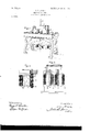
The invention itselt` will be better understood b v reference to the following specitication, which is to be taken in connection with the accompanying drawings, in which- Figure l is a perspective view of a reactance-coil built in accordance with my invention; Fig. 2, a view, partly in section, of the coils on one leg of the core of the reactancecoil; and Fig. 3, a view showing the circuits ot' the reactive coil.
The coils oil the apparatus may be mounted in any suitable manner, but in the present instance are supported by means of rods depending from the under side of the slate top l oi' a stand or table, the legs oi' which are indicated at 2 and 3. The core of the reactance device is indicated at 4 and is formed of laminated iron arranged in U shape, the cruciform cross-section oi the core being perhaps best illustrated at 5 in Fig. 3. This core is arranged to be raised and lowered in the coils by means of a cord or rope 6, and in order to prevent abrasion of the coils by the sharp edges of the core I provide the legs of the latter with smooth cylindrical sleeves 7 8 of fiber or other suitable non-conducting material. Each leg oi' the core 4 moves into and out of two concentrically-arranged coils, as represented at 9 lO and 11 12 in Fig. 3, the outer coils 10 and 12 being shown also in perspective in Fig. 1. By providing two coils i'or each leg of the core, these coils being separated by an airspace, as indicated, I secure a large radiatingsurface, thereby permitting the ready dispersion ot'lieat generated in the windings. The manner of supporting these coils is indicated in Fig. 2, which shows at 13 one of the plurality of supporting-rods which extend down through the space between the coils l1 l2 and which serve to clamp the coils in place between the insulating-blocks, such as at 14 and 15, located, respectively, at the upper and lower edges of the coils. By subdividing th'e coils, as shown, in addition to reducing the heating thereof I [ind that I may obtain an important advantage, when it is desired, for the purpose ot' varying the reactance that one-haltl the coils should be placed in multiple with the other half. Instead of connecting the coilson each leg in series with each other and then multiply, connecting the series-connected coils on one leg with the series-connected coils on the other, I make use ofa diderent system of connections, the outside coil on one leg, such as 10, being connected in series with the inside coil ll on the other leg, the remaining coils being' also connected in series with each other and the two pairs or sets of series-connected coils then in multiple with each other, as shown. This cross connection of the two sections ot' the coils on the two legs of the core 5 distributes or equalizes the effect ot' any inequality of 75 reactance oit the two multiply-connected circuits, due either to slight irregularities in the coils and the positions ot' the coils relatively to each other and also due to any unsymmetrical relation, slight though itmay be, between SO the core oi" the apparatus and its respective sets of coils. An equal division ot' current between the two multiply-connected circuits is thus insured, thus preventing the overload and possible injury or burn-out which might S 5 otherwise take place it' one coil or set ot coils were to take more than its share of the total current. The amount ot' reactance may be varied by adjusting the core and also by changing the connections of the coils.
What I claim as new, and desire to secure by Letters Patent of the United States, is-
1. In a reactance device, the combination of a movable core, two concentric coils i'or each ot' two legs of said core, and cross connections 95 between the coils such that the inner coil on each leg of the core is in series with the outer coil on the other leg oi' the core, the two sets with respect to said core, one set of coils being located on said core at a distance from the other set of coils, and conductors crossconnecting the coils of said sets in multiple.
In Witness whereof I have hereunto set my hand this 31st day of January, 1903.
JOHN J. FRANK.
Titnessesz BENJAMIN B. HULL, HELEN ORFORD.
Priority Applications (1)
| Application Number | Priority Date | Filing Date | Title |
|---|---|---|---|
| US14160103A US771237A (en) | 1903-02-02 | 1903-02-02 | Reactance-coil. |
Applications Claiming Priority (1)
| Application Number | Priority Date | Filing Date | Title |
|---|---|---|---|
| US14160103A US771237A (en) | 1903-02-02 | 1903-02-02 | Reactance-coil. |
Publications (1)
| Publication Number | Publication Date |
|---|---|
| US771237A true US771237A (en) | 1904-10-04 |
Family
ID=2839723
Family Applications (1)
| Application Number | Title | Priority Date | Filing Date |
|---|---|---|---|
| US14160103A Expired - Lifetime US771237A (en) | 1903-02-02 | 1903-02-02 | Reactance-coil. |
Country Status (1)
| Country | Link |
|---|---|
| US (1) | US771237A (en) |
-
1903
- 1903-02-02 US US14160103A patent/US771237A/en not_active Expired - Lifetime
Similar Documents
| Publication | Publication Date | Title |
|---|---|---|
| US3078411A (en) | Electrical apparatus | |
| US771237A (en) | Reactance-coil. | |
| US2201845A (en) | Dynamoelectric machine | |
| US1629462A (en) | Winding for electrical apparatus | |
| US1891716A (en) | Winding for dynamo electric machines | |
| US1238304A (en) | Dynamo-electric machine. | |
| US1872293A (en) | Transformer | |
| US1493849A (en) | Arc-welding transformer | |
| US1301636A (en) | High-voltage-current transformer. | |
| US1539670A (en) | Stationary induction apparatus | |
| US980986A (en) | Alternating-current electric motor. | |
| US1242649A (en) | Transformer-winding. | |
| US2150382A (en) | Regulating transformer | |
| US1741200A (en) | Transformer | |
| US755829A (en) | Controlling induction-motors. | |
| US3145358A (en) | Winding transposition | |
| US684168A (en) | Regulating device for arc-lamp circuits. | |
| US914941A (en) | Transformer structure. | |
| US1764319A (en) | Voltage-control system | |
| US2830254A (en) | Current divider circuit for high current tap changing under load mechanism | |
| US1140920A (en) | Transformer. | |
| US2079843A (en) | Transformer | |
| US733341A (en) | Variable-speed induction-motor. | |
| US767503A (en) | Earth-shield for transformers. | |
| US678233A (en) | Flux-screen for transformers. |