US7701874B2 - Intelligent sensor network - Google Patents
Intelligent sensor network Download PDFInfo
- Publication number
- US7701874B2 US7701874B2 US11/160,216 US16021605A US7701874B2 US 7701874 B2 US7701874 B2 US 7701874B2 US 16021605 A US16021605 A US 16021605A US 7701874 B2 US7701874 B2 US 7701874B2
- Authority
- US
- United States
- Prior art keywords
- sensor
- network
- data
- employing
- sensors
- Prior art date
- Legal status (The legal status is an assumption and is not a legal conclusion. Google has not performed a legal analysis and makes no representation as to the accuracy of the status listed.)
- Active, expires
Links
Images


Classifications
-
- H—ELECTRICITY
- H04—ELECTRIC COMMUNICATION TECHNIQUE
- H04W—WIRELESS COMMUNICATION NETWORKS
- H04W40/00—Communication routing or communication path finding
- H04W40/24—Connectivity information management, e.g. connectivity discovery or connectivity update
- H04W40/246—Connectivity information discovery
-
- H—ELECTRICITY
- H04—ELECTRIC COMMUNICATION TECHNIQUE
- H04L—TRANSMISSION OF DIGITAL INFORMATION, e.g. TELEGRAPHIC COMMUNICATION
- H04L67/00—Network arrangements or protocols for supporting network services or applications
- H04L67/01—Protocols
- H04L67/12—Protocols specially adapted for proprietary or special-purpose networking environments, e.g. medical networks, sensor networks, networks in vehicles or remote metering networks
Definitions
- the invention relates generally to the field of data communications and more specifically to a method, system, and program product for the deployment and use of fused sensors in an arbitrary area or volume.
- Bevington et al. describe distributed sensor networks useful for battlefield surveillance and target tracking and that are capable of adaptation and self-organization. See Bevington et al., “Target Tracking for Heterogeneous Smart Sensor Networks,” in Battlespace Digitization and Network-Centric Warfare, Proceedings of SPIE v.4396 (2001), which is hereby incorporated herein by reference.
- Other uses for multi-sensor systems may include, for example, the location and tracking of individuals or vehicles, security systems, wireless telecommunications and data transfer systems, and environmental monitoring applications.
- the failure of the centralized data routing point or any sensor along the path to that point may render some or all of the network inoperable.
- This inoperability may result not only in the inability of the network to fuse the data provided by multiple sensors, but may also isolate individual sensors with respect to each other. In military applications, such isolation of network components can have disastrous consequences.
- the present invention provides a method, system, and program product for the deployment and use of an intelligent sensor network. More particularly, the method, system, and program product of the present invention enable the deployment and use of fused sensors in an arbitrary area or volume.
- the invention provides a method for employing a multi-sensor network, the method comprising the steps of employing a first sensor, employing a plurality of additional sensors, a position of each additional sensor within the network being relative in at least two dimensions to only one of the first sensor and an adjacent sensor nearer the first sensor, and employing a routing algorithm for determining a routing path for data in the network.
- the invention provides a system for employing a multi-sensor network, the system comprising means for employing a first sensor, means for employing a plurality of additional sensors, a position of each additional sensor within the network being relative in at least two dimensions to only one of the first sensor and an adjacent sensor nearer the first sensor, and means for employing a routing algorithm for determining a routing path for data in the network.
- the invention provides a computer readable medium comprising computer program code embodied therein for employing a multi-sensor network, the program product comprising program code for employing a first sensor, program code for employing a plurality of additional sensors, a position of each additional sensor within the network being relative in at least two dimensions to only one of the first sensor and an adjacent sensor nearer the first sensor, and program code for employing a routing algorithm for determining a routing path for data in the network.
- FIG. 1 shows a multi-sensor network according to the invention.
- FIG. 2 shows a data routing path within the network of FIG. 1 .
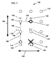
- FIG. 3 shows an adaptive data routing path within the network of FIG. 1 .
- FIG. 4 shows a sensor network with an adaptable central node.
- FIG. 5 shows a flow chart of a method for employing a network according to the invention.
- FIG. 6 shows a flow chart of a routing algorithm according to the invention.
- FIG. 7 shows a diagram of a system for employing a multi-sensor network according to the invention.
- a two-dimensional network 100 of sensors e.g., network nodes 110 , 112 is shown.
- Sensors 110 , 112 include any device capable of acquiring and/or transmitting data relating to an environmental or situational state. Suitable sensors include, for example, devices capable of acquiring and/or transmitting acoustical, visual, positional, directional, motion, temporal, vibrational, seismic, electrical, magnetic, thermal, chemical, biological, or radiological data.
- additional sensors 110 deployed within the network 100 are positioned along a first axis 150 and a second axis 160 relative to only one of first sensor 112 or an adjacent sensor nearer first sensor 112 .
- first sensor 112 functions as the origin of the network, having coordinates 122 of (0,0). All subsequently deployed sensors 110 have coordinates ultimately relative to first sensor 112 , although actual determination of a sensor's coordinates is made either by direct comparison to first sensor 112 or by comparison to an adjacent sensor nearer first sensor 112 , the coordinates of which have already been determined.
- Axes 150 , 160 are arbitrary and relative only to each other and defined upon placement of first sensor 112 . A user may choose, for example, to align axes 150 , 160 with cardinal directions or any other orientation the user prefers. A default orientation for axes 150 , 160 may similarly be employed.
- All data acquired by a sensor 110 are routed to first sensor 112 via the nearest adjacent sensor. Such routing is done according to an algorithm of orthogonal shifts within the network 100 of sensors 110 , 112 such that each transmission of data to the nearest adjacent sensor moves the data closer to first sensor 112 while maintaining the greatest possible coordinate distance from first sensor 112 . Such an algorithm ensures that data transmission within the network utilizes as many “straight line” transmissions as possible.
- first sensor 112 Data routed to first sensor 112 is then provided to a system, network, or device external to sensor network 100 . That is, first sensor 112 serves as a portal to other systems, networks, or devices capable of utilizing data acquired by sensor network 100 .
- Suitable systems, networks, and devices include, for example, communications systems and networks, weapons systems, display devices, and recording devices.
- an activated sensor 114 has received data. Numerous pathways are possible for transmitting the data to first sensor 112 .
- the nearest sensors adjacent activated sensor 114 are first determined.
- the nearest adjacent sensors to activated sensor 114 are sensor 116 and sensor 130 .
- the nearest adjacent sensor that maintains a maximum distance from first sensor 112 is chosen.
- that sensor is sensor 116 , having coordinates 126 of (0, ⁇ 2).
- Sensor 130 having coordinates 140 of ( ⁇ 1, ⁇ 1), is not chosen, as it is closer to first sensor 112 along axis 160 than is sensor 116 . Accordingly, data is first transferred 152 to sensor 116 along axis 150 .
- transmission to first sensor 112 is a “straight line” transfer, i.e. along a single axis 160 .
- Data is second transferred 162 to sensor 118 having coordinates 128 (0, ⁇ 1) and third transferred 164 to first sensor 112 .
- a user definable axis preference may be included in the algorithm.
- the two routing paths will satisfy the algorithm's requirements that the first transmission move the data closer to first sensor 112 while maintaining a maximum distance from first sensor 112 .
- the two routing paths are: (1) sensor 130 to sensor 132 to first sensor 112 and (2) sensor 130 to sensor 118 to first sensor 112 .
- an axis will be defined by a user as the preferred axis for first transmission. For example, if the preferred axis was axis 150 , the routing path chosen by the algorithm would be path (2), above.
- the present invention provides a robust, intelligent, and adaptable multi-sensor network. That is, unlike the networks known in the art, which generally depend upon uninterrupted routing paths to transmit data, the network of the present invention adapts its routing paths in response to the unavailability of individual sensors. This robustness and adaptability is critical in military applications, where communications and data acquisition networks must be able to continue functioning following the inactivation or destruction of one or more individual network sensors. Other networks may similarly benefit from the robustness and adaptability of the present invention, including, for example, high-speed Internet or telecommunications networks and environmental monitoring networks.
- sensor 116 is again the sensor preferred by the algorithm, but is unavailable to transmit data received by sensor 114 .
- This unavailability may be due to damage to or destruction of sensor 116 or may simply be due to its occupation with the transmission of data from another sensor.
- the preferred routing path will adapt to bypass sensor 116 .
- the only remaining sensor within network 100 that satisfies the algorithm's criteria i.e. that the first transmission move the data closer to first sensor 112 while maintaining a maximum distance from first sensor 112
- the algorithm of the present invention will follow routing path (2) described above with respect to FIG. 2 .
- the data from sensor 114 is first transferred 166 to sensor 130 and second transferred 168 to sensor 132 along axis 160 . Finally, via an orthogonal shift, data is third transferred 154 to first sensor 112 along axis 150 . While the network show in FIGS. 1-3 comprises two dimensions, it should be recognized that the teachings of the present invention are equally applicable to three-dimensional networks.
- first sensor 112 will become disabled or otherwise unavailable. For at least two reasons, such an occurrence is more problematic than the unavailable sensor in FIG. 3 , as described above. First, since all routing paths ultimately lead to first sensor 112 , it is not possible to utilize an alternate routing path that does not include first sensor 112 . Second, as described above, first sensor 112 acts as the portal to other systems, networks, or devices capable of utilizing data acquired by sensor network 100 . Thus, if first sensor 112 is unavailable, all data acquired by sensor network 100 is also unavailable to such other systems, networks, or devices.
- a sensor 110 other than first sensor 112 is capable of functioning as the network portal to other systems, networks, or devices, should first sensor 112 become unavailable.
- first sensor 112 when it is functioning properly, transmits a status signal 170 to each sensor 118 , 132 , 134 , 136 nearest first sensor 112 .
- Status signal 170 may be transmitted in any number of manners, including, for example, continuously or periodically. While status signal 170 is received by sensors 118 , 132 , 134 , 136 , first sensor 112 continues to act as the network portal.
- first sensor 112 transmits an “unavailable” signal 180 upon becoming unavailable.
- first sensor 112 As can be seen in FIG. 4 , four sensors 118 , 132 , 134 , 136 are equally near first sensor 112 . In a three-dimensional sensor network, as many as six sensors may be equally near first sensor 112 . Accordingly, some method must be employed to choose a sensor to function as the new network portal from among those sensors equally near first sensor 112 . As described above, use of a user definable axis preference will limit the sensors from among which the new network portal must be chosen to a maximum of two. To chose between this maximum of two, a user definable polarity preference may be similarly employed, whereby the preferred sensor is the one which lies on the “positive” or “negative” side of the chosen axis. For example, still referring to FIG.
- first axis 150 is the preferred axis
- the sensor to function as the new network portal will be chosen from among sensor 132 and sensor 136 . If the preferred polarity is “positive,” sensor 136 will be chosen, as it lies on the “positive” side of first axis 150 , relative to first sensor 112 .
- the coordinates of the chosen sensor are redesignated 0,0 and the coordinates of all remaining sensors in network 100 are redesignated relative to the chosen sensor.
- the coordinates 146 of sensor 136 are redesignated from 1,0 to 0,0 while the coordinates 142 of sensor 132 are redesignated from ⁇ 1,0 to ⁇ 2,0, the coordinates 144 of sensor 134 are redesignated from 0,1 to ⁇ 1,1, etc.
- a flow chart is shown for a method of employing a network according to the invention.
- a first network node first sensor 112 in FIGS. 1-4
- the network of the present invention has a physically arbitrary architecture, such that the establishment of the first node is independent of any axes, which will be defined relative to the first node.
- additional nodes are established relative only to the first node in a first and second dimension. It is possible to establish at least two additional nodes that reside within a two-dimensional plane relative to the first node. However, additional nodes in excess of two (i.e., the fourth or greater node added to the network) may reside outside this two-dimensional plane.
- step S 3 it is determined whether any additional nodes reside outside the two-dimensional plane relative to the first node. If no network nodes reside outside this two-dimensional plane, the routing algorithm described above is employed at step S 5 to determine a data routing path to be followed in the transmission of data from an activated node to the first node. If, however, one or more nodes reside outside the two-dimensional plane relative to the first node, at step S 4 , the position of all nodes must is determined in a third dimension relative to the first node. After so determining the position of each node, the routing algorithm is employed at step S 5 as above.
- FIG. 6 shows a flow chart for the routing algorithm of step S 5 in FIG. 5 .
- the nearest node(s) e.g., sensor(s)
- the nearest node(s) adjacent an activated node is determined.
- the nearest node(s) e.g., sensor(s) adjacent an activated node is determined.
- step S 5 B it is determined which of the nodes of step S 5 A is furthest from the first node in any direction (i.e., along any of a fist, second, or third axis).
- step S 5 C it is determined whether more than one node is identified at step S 5 B. That is, as described above, it is possible that more than one nearest adjacent node will be equally distant from the first node.
- step S 5 D the data is first routed to the node identified at step S 5 B. If, however, more than one node is identified at step S 5 B, a user-defined axis preference is employed at step S 5 E. Accordingly, at step S 5 F, data is first routed to the node along the preferred axis.
- networks employed according to the present invention are robust, intelligent, and adaptable due to the use of an ad hoc routing algorithm.
- This algorithm enables the efficient transmission of data via network nodes by preferring routing paths that minimize orthogonal shifts, maximize “straight line” transmissions, and route around nodes as they become unavailable for data transmission.
- FIG. 7 is a block diagram of a system 200 capable of employing a multi-sensor network in accordance with the invention.
- System 200 includes a computing device 210 having a memory 212 , a processor 214 , an input/output (I/O) interface 216 , and a bus 218 .
- Computing device 210 is shown in communication with an external I/O device/resource 224 and a storage system 220 , which together comprise a computer infrastructure 204 .
- processor 214 executes computer program code such as sensor system 230 , that is stored in memory 212 and/or storage system 220 .
- processor 214 can read and/or write data, such as that of sensor system 230 , to/from memory 212 , storage system 220 , and/or I/O interface 216 .
- Bus 218 provides a communication link between each of the components in computing device 210 .
- I/O device 224 may comprise any known type of device that enables a user to interact with computing device 210 or any device that enables computing device 210 to communicate with one or more other computing devices, including a network system, modem, keyboard, mouse, scanner, voice recognition system, CRT, printer, disc drive, etc. Additional components, such as cache memory, communication systems, system software, etc., may also be incorporated into system 200 .
- computing device 210 can comprise any general purpose computing article of manufacture capable of executing computer program code installed by a user (e.g., a personal computer, server, handheld device, etc.).
- computing device 210 and sensor system 230 are only representative of various possible computing devices that may perform the various process steps of the invention.
- computing device 210 can comprise any specific purpose computing article of manufacture comprising hardware and/or computer program code for performing specific functions, any computing article of manufacture that comprises a combination of specific purpose and general purpose hardware/software, or the like.
- the program code and hardware can be created using standard programming and engineering techniques, respectively.
- system 200 is only illustrative of various types of systems for implementing the invention.
- system 200 may comprise two or more computing devices (e.g., a server cluster) that communicate over any type of wired and/or wireless communications link, such as a network, a shared memory, or the like, to perform the various process steps of the invention.
- the communications link comprises a network
- the network can comprise any combination of one or more types of networks (e.g., the Internet, a wide area network, a local area network, a virtual private network, etc.).
- sensor system 230 enables computing device 210 to employ a multi-sensor network.
- sensor system 230 is shown including a first sensor system 232 , an additional sensor system 234 , and an algorithm system 236 . It should be understood that some of the various systems of FIG. 6 can be implemented independently, combined, and/or stored in memory for one or more separate computing devices 210 that communicate over a network. Further, is should be understood that some of the systems and/or functionality may not be implemented, or additional systems and/or functionality may be included as part of system 200 .
- the invention provides a computer-readable medium that includes computer program code to enable a computer infrastructure to employ a multi-sensor network.
- the computer-readable medium includes program code, such as sensor system 230 , that implements each of the various process steps of the invention.
- the term “computer-readable medium” comprises one or more of any type of physical embodiment of the program code.
- the computer-readable medium can comprise program code embodied on one or more portable storage articles of manufacture (e.g., a compact disc, a magnetic disk, a tape, etc.), on one or more data storage portions of a computing device, such as memory 212 and/or storage system 220 (e.g., a fixed disk, a read-only memory, a random access memory, a cache memory, etc.).
- portable storage articles of manufacture e.g., a compact disc, a magnetic disk, a tape, etc.
- data storage portions of a computing device such as memory 212 and/or storage system 220 (e.g., a fixed disk, a read-only memory, a random access memory, a cache memory, etc.).
- the invention may provide a method for generating a system for employing a multi-sensor network.
- a computer infrastructure such as computer infrastructure 204
- one or more systems for performing the process steps of the invention can be obtained (e.g., created, purchased, used, modified, etc.) and deployed to the computer infrastructure.
- the deployment of each system can comprise one or more of (1) installing program code on a computing device, such as computing device 210 , from a computer-readable medium; (2) adding one or more computing devices to the computer infrastructure; and (3) incorporating and/or modifying one or more existing systems of the computer infrastructure to enable the computer infrastructure to perform the process steps of the invention.
- program code and “computer program code” are synonymous and mean any expression, in any language, code, or notation, of a set of instructions intended to cause a computing device having an information processing capability to perform a particular function either directly or after either or both of the following: (a) conversion to another language, code, or notation; and/or (b) reproduction in a different material form.
- program code can be embodied as one or more types of program products, such as an application/software program, component software/a library of functions, an operating system, a basic I/O system/driver for a particular computing and/or I/O device, and the like.
- an employment system 200 could be created, maintained and/or deployed by a service provider that offers the functions described herein for customers. That is, a service provider could offer to employ a multi-sensor network as described above.
Landscapes
- Engineering & Computer Science (AREA)
- Computer Networks & Wireless Communication (AREA)
- Signal Processing (AREA)
- Health & Medical Sciences (AREA)
- Computing Systems (AREA)
- General Health & Medical Sciences (AREA)
- Medical Informatics (AREA)
- Arrangements For Transmission Of Measured Signals (AREA)
Abstract
Description
Claims (15)
Priority Applications (1)
| Application Number | Priority Date | Filing Date | Title |
|---|---|---|---|
| US11/160,216 US7701874B2 (en) | 2005-06-14 | 2005-06-14 | Intelligent sensor network |
Applications Claiming Priority (1)
| Application Number | Priority Date | Filing Date | Title |
|---|---|---|---|
| US11/160,216 US7701874B2 (en) | 2005-06-14 | 2005-06-14 | Intelligent sensor network |
Publications (2)
| Publication Number | Publication Date |
|---|---|
| US20060280129A1 US20060280129A1 (en) | 2006-12-14 |
| US7701874B2 true US7701874B2 (en) | 2010-04-20 |
Family
ID=37524022
Family Applications (1)
| Application Number | Title | Priority Date | Filing Date |
|---|---|---|---|
| US11/160,216 Active 2029-02-18 US7701874B2 (en) | 2005-06-14 | 2005-06-14 | Intelligent sensor network |
Country Status (1)
| Country | Link |
|---|---|
| US (1) | US7701874B2 (en) |
Cited By (3)
| Publication number | Priority date | Publication date | Assignee | Title |
|---|---|---|---|---|
| US10884099B2 (en) | 2014-07-21 | 2021-01-05 | Sikorsky Aircraft Corporation | Coverage optimization for sensor networks |
| US11022511B2 (en) | 2018-04-18 | 2021-06-01 | Aron Kain | Sensor commonality platform using multi-discipline adaptable sensors for customizable applications |
| US20210392059A1 (en) * | 2015-06-05 | 2021-12-16 | Cisco Technology, Inc. | Auto update of sensor configuration |
Families Citing this family (9)
| Publication number | Priority date | Publication date | Assignee | Title |
|---|---|---|---|---|
| JP4529144B2 (en) * | 2004-08-11 | 2010-08-25 | 日本電気株式会社 | Virtual LAN system and node device |
| US20080211690A1 (en) * | 2005-01-04 | 2008-09-04 | Robert Theodore Kinasewitz | E-field/b-field/acoustic ground target data fused multisensor method and apparatus |
| US8892704B2 (en) * | 2006-04-07 | 2014-11-18 | The Mitre Corporaton | Dynamic rule-based distributed network operation for wireless sensor networks |
| WO2008096909A1 (en) * | 2007-02-04 | 2008-08-14 | Ki-Hyung Kim | Method for routing a path setting in a wireless sensor network and apparatus for performing the same |
| US8085792B1 (en) * | 2007-06-29 | 2011-12-27 | Google Inc. | Traffic-oblivious load balancing protocol for sensor networks |
| US8392401B1 (en) | 2007-06-29 | 2013-03-05 | Google Inc. | Query partitioning to decompose hotspots in sensor networks |
| US8649260B2 (en) * | 2008-03-14 | 2014-02-11 | Volvo Technology Corporation | System and method for providing a stable and tamper proof communication between a vehicle, a vehicle related unit, and a remote system |
| KR101074127B1 (en) | 2008-12-16 | 2011-10-17 | 한국전자통신연구원 | Method and apparatus for commissioning sensor node |
| US10212231B2 (en) | 2015-01-07 | 2019-02-19 | Passport Systems, Inc. | Methods and systems for detecting a material source using a server and networked sensors |
Citations (19)
| Publication number | Priority date | Publication date | Assignee | Title |
|---|---|---|---|---|
| US5005142A (en) | 1987-01-30 | 1991-04-02 | Westinghouse Electric Corp. | Smart sensor system for diagnostic monitoring |
| US5202661A (en) | 1991-04-18 | 1993-04-13 | The United States Of America As Represented By The Secretary Of The Navy | Method and system for fusing data from fixed and mobile security sensors |
| US5907559A (en) | 1995-11-09 | 1999-05-25 | The United States Of America As Represented By The Secretary Of Agriculture | Communications system having a tree structure |
| US6013108A (en) | 1997-03-18 | 2000-01-11 | Endevco Corporation | Intelligent sensor system with network bus |
| US20020050931A1 (en) | 2000-10-31 | 2002-05-02 | Lieberman Robert A. | Surveillance system and method |
| US6449382B1 (en) | 1999-04-28 | 2002-09-10 | International Business Machines Corporation | Method and system for recapturing a trajectory of an object |
| US20030023534A1 (en) | 2001-06-11 | 2003-01-30 | Shubha Kadambe | Method and apparatus for determining and assessing information to be collected based on information-theoretic measures |
| US20030073406A1 (en) | 2001-10-17 | 2003-04-17 | Benjamin Mitchell A. | Multi-sensor fusion |
| US20030114986A1 (en) | 2001-12-17 | 2003-06-19 | Aravind Padmanabhan | Architectures of sensor networks for biological and chemical agent detection and identification |
| US20030179084A1 (en) | 2002-03-21 | 2003-09-25 | Ford Global Technologies, Inc. | Sensor fusion system architecture |
| US20040028023A1 (en) | 2002-04-18 | 2004-02-12 | Sarnoff Corporation | Method and apparatus for providing ad-hoc networked sensors and protocols |
| US20040064260A1 (en) | 2001-12-17 | 2004-04-01 | Aravind Padmanabhan | Architectures of sensor networks for biological and chemical agent detection and identification |
| US20050207376A1 (en) * | 2004-03-19 | 2005-09-22 | Nortel Networks Limited | Method and apparatus for sensor network routing |
| US20060013154A1 (en) * | 2004-07-16 | 2006-01-19 | Ajou University Industry Cooperation Foundation | Directional flooding method in wireless sensor network |
| US20060104270A1 (en) * | 2004-11-16 | 2006-05-18 | Inching Chen | Method and apparatus for communicating within a segmented network |
| US20060153154A1 (en) * | 2004-12-29 | 2006-07-13 | Samsung Electronics Co., Ltd. | Data forwarding method for reliable service in sensor networks |
| US20060176176A1 (en) * | 2005-02-04 | 2006-08-10 | Samsung Electronics Co., Ltd. | Apparatus and method for setting route in sensor network |
| US20060178156A1 (en) * | 2005-01-18 | 2006-08-10 | Samsung Electronics Co., Ltd. | Routing method in a wireless sensor network |
| US20060239216A1 (en) * | 2005-04-26 | 2006-10-26 | Wai Chen | Cross-layer self-healing in a wireless ad-hoc network |
-
2005
- 2005-06-14 US US11/160,216 patent/US7701874B2/en active Active
Patent Citations (19)
| Publication number | Priority date | Publication date | Assignee | Title |
|---|---|---|---|---|
| US5005142A (en) | 1987-01-30 | 1991-04-02 | Westinghouse Electric Corp. | Smart sensor system for diagnostic monitoring |
| US5202661A (en) | 1991-04-18 | 1993-04-13 | The United States Of America As Represented By The Secretary Of The Navy | Method and system for fusing data from fixed and mobile security sensors |
| US5907559A (en) | 1995-11-09 | 1999-05-25 | The United States Of America As Represented By The Secretary Of Agriculture | Communications system having a tree structure |
| US6013108A (en) | 1997-03-18 | 2000-01-11 | Endevco Corporation | Intelligent sensor system with network bus |
| US6449382B1 (en) | 1999-04-28 | 2002-09-10 | International Business Machines Corporation | Method and system for recapturing a trajectory of an object |
| US20020050931A1 (en) | 2000-10-31 | 2002-05-02 | Lieberman Robert A. | Surveillance system and method |
| US20030023534A1 (en) | 2001-06-11 | 2003-01-30 | Shubha Kadambe | Method and apparatus for determining and assessing information to be collected based on information-theoretic measures |
| US20030073406A1 (en) | 2001-10-17 | 2003-04-17 | Benjamin Mitchell A. | Multi-sensor fusion |
| US20030114986A1 (en) | 2001-12-17 | 2003-06-19 | Aravind Padmanabhan | Architectures of sensor networks for biological and chemical agent detection and identification |
| US20040064260A1 (en) | 2001-12-17 | 2004-04-01 | Aravind Padmanabhan | Architectures of sensor networks for biological and chemical agent detection and identification |
| US20030179084A1 (en) | 2002-03-21 | 2003-09-25 | Ford Global Technologies, Inc. | Sensor fusion system architecture |
| US20040028023A1 (en) | 2002-04-18 | 2004-02-12 | Sarnoff Corporation | Method and apparatus for providing ad-hoc networked sensors and protocols |
| US20050207376A1 (en) * | 2004-03-19 | 2005-09-22 | Nortel Networks Limited | Method and apparatus for sensor network routing |
| US20060013154A1 (en) * | 2004-07-16 | 2006-01-19 | Ajou University Industry Cooperation Foundation | Directional flooding method in wireless sensor network |
| US20060104270A1 (en) * | 2004-11-16 | 2006-05-18 | Inching Chen | Method and apparatus for communicating within a segmented network |
| US20060153154A1 (en) * | 2004-12-29 | 2006-07-13 | Samsung Electronics Co., Ltd. | Data forwarding method for reliable service in sensor networks |
| US20060178156A1 (en) * | 2005-01-18 | 2006-08-10 | Samsung Electronics Co., Ltd. | Routing method in a wireless sensor network |
| US20060176176A1 (en) * | 2005-02-04 | 2006-08-10 | Samsung Electronics Co., Ltd. | Apparatus and method for setting route in sensor network |
| US20060239216A1 (en) * | 2005-04-26 | 2006-10-26 | Wai Chen | Cross-layer self-healing in a wireless ad-hoc network |
Non-Patent Citations (7)
| Title |
|---|
| "Remote Robotic Reconnaissance Vehicle," R3V, SPAWAR Systems Center San Diego (US Naval Research), 2003, Google Search, pp. 1-5. |
| Baertlein, Brian, "Progress in Sensor Fusion and IR Modeling at Ohio State University," Research on Demining Technologies Joint Workshop, European Commission Joint Research Center, Jul. 12-14, 2000, pp. 1-21. |
| Bevington, James E., et al., "Target Tracking for Heterogeneous Smart Sensor Networks," Proceedings of SPIE, vol. 4396, 2001, pp. 20-30. |
| J. Zhang, H. Shi, "Energy-Efficient Routing for 2D Grid Wireless Sensor Networks", In Proceedings of the IEEE International Conference on Information Technology: Research and Education 2003, ITRE 2003, Newark, New Jersy, Aug. 2003. * |
| L. Venkata, "Routing Algorithm for Large Scale Wireless Sensor Networks", Texas A&M Graduate Studies-Computer Science, Dec. 2004. * |
| R. Luo, O. Chen, L.C. Tu, "Nodes Localization through Data Fusion in Sensor Network", In Proceedings of the 19th International Conference on Advanced Information Network and Applications, AINA 2005. * |
| Y. Ge, Q. Yin S.K. Tan Q. Yao B.S. Yao W. Seah, "Green: A Grid-based Energy Efficient Probabilistic Routing in Wireless Sensor Networks", Vehicular Technology Conference 2005, IEEE 61st, 2005. * |
Cited By (3)
| Publication number | Priority date | Publication date | Assignee | Title |
|---|---|---|---|---|
| US10884099B2 (en) | 2014-07-21 | 2021-01-05 | Sikorsky Aircraft Corporation | Coverage optimization for sensor networks |
| US20210392059A1 (en) * | 2015-06-05 | 2021-12-16 | Cisco Technology, Inc. | Auto update of sensor configuration |
| US11022511B2 (en) | 2018-04-18 | 2021-06-01 | Aron Kain | Sensor commonality platform using multi-discipline adaptable sensors for customizable applications |
Also Published As
| Publication number | Publication date |
|---|---|
| US20060280129A1 (en) | 2006-12-14 |
Similar Documents
| Publication | Publication Date | Title |
|---|---|---|
| US7701874B2 (en) | Intelligent sensor network | |
| EP1673928B1 (en) | Arrangement for autonomous mobile network nodes to organize a wireless mobile network based on detected physical and logical changes | |
| Newman et al. | Ubiquitous tracking for augmented reality | |
| US8781431B2 (en) | Techniques for determining communication state using accelerometer data | |
| US7480395B2 (en) | Decentralized detection, localization, and tracking utilizing distributed sensors | |
| Eldrandaly et al. | Internet of spatial things: A new reference model with insight analysis | |
| US8243711B2 (en) | Method for generating and registering identification in wireless sensor network | |
| Phoha et al. | Sensor network operations | |
| Abu znaid et al. | Low communication cost (LCC) scheme for localizing mobile wireless sensor networks | |
| Ryu et al. | A review on sensor network issues and robotics | |
| Bagci et al. | Ubiquitous mobile agent system in a P2P-network | |
| Al Nuaimi et al. | Web-based wireless sensor networks: a survey of architectures and applications | |
| Rooker et al. | Combining exploration and ad-hoc networking in robocup rescue | |
| Satoh | SpatialAgents: Integrating user mobility and program mobility in ubiquitous computing environments | |
| Seah et al. | TARANTULAS: mobility-enhanced wireless sensor-actuator networks | |
| Biswas et al. | A networked mobile sensor test-bed for collaborative multi-target tracking applications | |
| Malek et al. | A mobile computing approach for navigation purposes | |
| Gantayat et al. | Award—Reward protocol based on clustering and trust level for routing in delay tolerant network | |
| Meriste et al. | Location awareness of information agents | |
| Çayırpunar et al. | Dynamic robot networks for search and rescue operations | |
| Garg et al. | Data Discovery and Collection Architecture for Distributed IoT | |
| Dhaka et al. | Selecting Favorable Reference Nodes to Aid Localization in Wireless Sensor Networks | |
| Stringer | Message Delivery by Geo-spatially Routed Autonomous Assets | |
| Viely et al. | Trends, Technologies, and Future Challenges in Wireless Sensor Network's | |
| Carvalho et al. | A mobile agent-based middleware for opportunistic resource allocation and communications |
Legal Events
| Date | Code | Title | Description |
|---|---|---|---|
| AS | Assignment |
Owner name: INTERNATIONAL BUSINESS MACHINES CORPORATION,NEW YO Free format text: ASSIGNMENT OF ASSIGNORS INTEREST;ASSIGNORS:KLINE, ERIC V.;BHATIA, HARSARAN S.;SIGNING DATES FROM 20050609 TO 20050613;REEL/FRAME:016137/0348 Owner name: INTERNATIONAL BUSINESS MACHINES CORPORATION, NEW Y Free format text: ASSIGNMENT OF ASSIGNORS INTEREST;ASSIGNORS:KLINE, ERIC V.;BHATIA, HARSARAN S.;REEL/FRAME:016137/0348;SIGNING DATES FROM 20050609 TO 20050613 |
|
| FEPP | Fee payment procedure |
Free format text: PAYOR NUMBER ASSIGNED (ORIGINAL EVENT CODE: ASPN); ENTITY STATUS OF PATENT OWNER: LARGE ENTITY |
|
| STCF | Information on status: patent grant |
Free format text: PATENTED CASE |
|
| REMI | Maintenance fee reminder mailed | ||
| AS | Assignment |
Owner name: TWITTER, INC., CALIFORNIA Free format text: ASSIGNMENT OF ASSIGNORS INTEREST;ASSIGNOR:INTERNATIONAL BUSINESS MACHINES CORPORATION;REEL/FRAME:032075/0404 Effective date: 20131230 |
|
| FPAY | Fee payment |
Year of fee payment: 4 |
|
| SULP | Surcharge for late payment | ||
| FEPP | Fee payment procedure |
Free format text: MAINTENANCE FEE REMINDER MAILED (ORIGINAL EVENT CODE: REM.) |
|
| FEPP | Fee payment procedure |
Free format text: 7.5 YR SURCHARGE - LATE PMT W/IN 6 MO, LARGE ENTITY (ORIGINAL EVENT CODE: M1555) |
|
| MAFP | Maintenance fee payment |
Free format text: PAYMENT OF MAINTENANCE FEE, 8TH YEAR, LARGE ENTITY (ORIGINAL EVENT CODE: M1552) Year of fee payment: 8 |
|
| MAFP | Maintenance fee payment |
Free format text: PAYMENT OF MAINTENANCE FEE, 12TH YEAR, LARGE ENTITY (ORIGINAL EVENT CODE: M1553); ENTITY STATUS OF PATENT OWNER: LARGE ENTITY Year of fee payment: 12 |
|
| AS | Assignment |
Owner name: MORGAN STANLEY SENIOR FUNDING, INC., MARYLAND Free format text: SECURITY INTEREST;ASSIGNOR:TWITTER, INC.;REEL/FRAME:062079/0677 Effective date: 20221027 Owner name: MORGAN STANLEY SENIOR FUNDING, INC., MARYLAND Free format text: SECURITY INTEREST;ASSIGNOR:TWITTER, INC.;REEL/FRAME:061804/0086 Effective date: 20221027 Owner name: MORGAN STANLEY SENIOR FUNDING, INC., MARYLAND Free format text: SECURITY INTEREST;ASSIGNOR:TWITTER, INC.;REEL/FRAME:061804/0001 Effective date: 20221027 |