US7695044B2 - Under-cover support structure - Google Patents
Under-cover support structure Download PDFInfo
- Publication number
- US7695044B2 US7695044B2 US12/186,066 US18606608A US7695044B2 US 7695044 B2 US7695044 B2 US 7695044B2 US 18606608 A US18606608 A US 18606608A US 7695044 B2 US7695044 B2 US 7695044B2
- Authority
- US
- United States
- Prior art keywords
- under
- dash
- cover member
- support structure
- press
- Prior art date
- Legal status (The legal status is an assumption and is not a legal conclusion. Google has not performed a legal analysis and makes no representation as to the accuracy of the status listed.)
- Active
Links
Images


Classifications
-
- B—PERFORMING OPERATIONS; TRANSPORTING
- B62—LAND VEHICLES FOR TRAVELLING OTHERWISE THAN ON RAILS
- B62D—MOTOR VEHICLES; TRAILERS
- B62D25/00—Superstructure or monocoque structure sub-units; Parts or details thereof not otherwise provided for
- B62D25/08—Front or rear portions
- B62D25/14—Dashboards as superstructure sub-units
- B62D25/142—Dashboards as superstructure sub-units having ventilation channels incorporated therein
-
- B—PERFORMING OPERATIONS; TRANSPORTING
- B60—VEHICLES IN GENERAL
- B60K—ARRANGEMENT OR MOUNTING OF PROPULSION UNITS OR OF TRANSMISSIONS IN VEHICLES; ARRANGEMENT OR MOUNTING OF PLURAL DIVERSE PRIME-MOVERS IN VEHICLES; AUXILIARY DRIVES FOR VEHICLES; INSTRUMENTATION OR DASHBOARDS FOR VEHICLES; ARRANGEMENTS IN CONNECTION WITH COOLING, AIR INTAKE, GAS EXHAUST OR FUEL SUPPLY OF PROPULSION UNITS IN VEHICLES
- B60K37/00—Dashboards
-
- B—PERFORMING OPERATIONS; TRANSPORTING
- B60—VEHICLES IN GENERAL
- B60R—VEHICLES, VEHICLE FITTINGS, OR VEHICLE PARTS, NOT OTHERWISE PROVIDED FOR
- B60R13/00—Elements for body-finishing, identifying, or decorating; Arrangements or adaptations for advertising purposes
- B60R13/08—Insulating elements, e.g. for sound insulation
- B60R13/0815—Acoustic or thermal insulation of passenger compartments
- B60R13/083—Acoustic or thermal insulation of passenger compartments for fire walls or floors
-
- B—PERFORMING OPERATIONS; TRANSPORTING
- B62—LAND VEHICLES FOR TRAVELLING OTHERWISE THAN ON RAILS
- B62D—MOTOR VEHICLES; TRAILERS
- B62D25/00—Superstructure or monocoque structure sub-units; Parts or details thereof not otherwise provided for
- B62D25/08—Front or rear portions
- B62D25/14—Dashboards as superstructure sub-units
- B62D25/145—Dashboards as superstructure sub-units having a crossbeam incorporated therein
Definitions
- the present invention relates to a structure for supporting a vehicle interior cover, and particularly to a structure for supporting an under cover that covers the lower side of an instrument panel.
- Japanese Patent Application Publication No. 2004-268865 discloses an under-cover support structure for supporting an under cover member that is bridged between a dash panel and an instrument panel to cover the lower side of the instrument panel.
- the dash panel is provided in the front part of the vehicle cabin.
- the dash panel has stud bolts protruding from the cabin-side surface of the dash panel.
- the bolt holes are formed in an end portion on the side of the dash-panel of the under cover member. The stud bolts are inserted into the bolt holes, and thereby support the under cover member.
- Clips are provided at the rearward edge portion of the under cover member to serve as engaging members. Clip holes are formed in the lower forward edge portion of the instrument panel extending toward the dash panel. The clips are inserted into the clip holes from beneath to be locked therein.
- the under cover member is secured the dash panel and the instrument panel as follows. Firstly, the stud bolts provided on the dash panel are inserted into the bolt holes formed in the under cover member, so that the dash-panel-side end portion of the under cover member is engaged with the dash panel. Thereafter, the rearward edge portion of the under cover member is lifted upward, and the under cover member is thereby rotated about the locked dash-panel-side end portion of the under cover member. Consequently, the clips are inserted into the clip holes from beneath to be locked therein.
- the stud bolts which are provided on the dash panel in a protruding manner, need to be aligned with the bolt holes, which are formed in the dash-panel-side end portion of the under cover member, before being inserted thereto, for attaching the under cover member.
- the under cover member may possibly be damaged due to contact of the tip of the stud bolt with a peripheral part of the bolt hole of the under cover member.
- an object of the present invention is to provide an under-cover support structure which facilitates the attachment work of the under cover member.
- An aspect of the present invention is an under-cover support structure comprising: a dash panel provided in a front part of a vehicle cabin; a dash insulator attached to and extending along a cabin-side surface of the dash panel; an instrument panel mounted on the dash insulator in an inner side of the vehicle cabin; and an under cover member bridged between the cabin-side surface of the dash panel and a forward edge of a lower edge portion of the instrument panel, and covering a lower side of the instrument panel, the under cover member having a press-fit end portion on a side of the dash insulator, wherein the dash insulator is provided with a supporting portion which is elastically deformable by the press-fit end portion of the under cover member being pressed against the supporting portion.
- FIG. 1 is a perspective view showing a state in which an under cover member is press-fitted into a recessed portion of a dash insulator in an under-cover support structure according to an embodiment of the present invention.
- FIG. 2 is an exploded perspective view of the under-cover support structure according to the embodiment, for illustrating a configuration of the dash insulator, which is adhered to a dash panel, and an under cover member.
- FIG. 3 is a cross-sectional view of the under-cover support structure according to the embodiment, the view being taken along the III-III line in FIG. 1 .
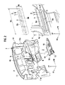
- FIG. 4 is an exploded perspective view of the under-cover support structure according to the embodiment, for illustrating a state in which the under cover member is fitted to the lower-surface side of an air-conditioning duct provided on a steering member inside an instrument panel.
- FIG. 5 is a perspective view illustrating a state in which the instrument panel is mounted on a vehicle body in which the under-cover support structure according to the embodiment is employed.
- FIG. 7 is an enlarged cross-sectional view of the part VII of the under-cover support structure according to the embodiment shown in FIG. 4 .
- FIG. 8 is a cross-sectional view of the under-cover support structure according to the embodiment, the view being taken along the line VIII-VIII in FIG. 5 .
- FIG. 9 is an enlarged cross-sectional view of the part IX of the under-cover support structure according to the embodiment shown in FIG. 8 .
- FIG. 10 is an enlarged cross-sectional view of the part X of the under-cover support structure according to the embodiment shown in FIG. 8 .
- FIG. 11 is a perspective view illustrating a configuration of the under cover member in the under-cover support structure according to the embodiment.
- FIG. 12 is a perspective view illustrating a configuration in which a duct insulator is set on the under cover member in the under-cover support structure according to the embodiment.
- FIG. 13 is a cross-sectional view illustrating a configuration of a part of an under-cover support structure according to a first example, the part being corresponding to that shown in FIG. 3 .
- FIG. 14 is a cross-sectional view illustrating a configuration of a part of an under-cover support structure according to a second example, the part being corresponding to that shown in FIG. 3 .
- FIG. 15 is a cross-sectional view illustrating a configuration of a part of an under-cover support structure according to a third example, the part being corresponding to that shown in FIG. 3 .
- FIG. 16 is a cross-sectional view illustrating a configuration of a part of an under-cover support structure according to a fourth example, the part being corresponding to that shown in FIG. 3 .
- description will be given mainly of a structure for supporting an under cover member 12 provided on the passenger-seat side in a left-hand drive automobile (on the right side in the vehicle).
- An under cover member is provided also on the driver-seat side (on the left side in the vehicle) as well as on the passenger-seat side, and has the substantially same configuration as that of the passenger-seat side. Accordingly, the description is omitted herein.
- the vehicle body 1 of the automobile includes an engine room 2 for housing an engine (not shown) therein, and a passenger compartment 3 located on the rear side in the front-rear direction of the vehicle, which serves as a vehicle cabin for passengers to be seated in.
- a dash panel 4 is provided between the engine room 2 and the passenger compartment 3 , and defines the engine room 2 and the passenger compartment 3 .
- a dash insulator 5 serving as a sound-absorbing member is adhered to a surface 4 a of the dash panel 4 on a side of the vehicle cabin (hereinafter, simply referred to as “cabin-side surface 4 a ”).
- a recessed portion 6 serving as a supporting portion for supporting the forward edge portion of the below-mentioned under cover member 12 is formed.
- the recessed portion 6 is a recess that extends approximately horizontally in the vehicle-width direction, and that substantially has a shape of a slotted hole when seen from the front thereof.
- the recessed portion 6 includes a bottom portion 7 having an elongated narrow shape, and a guide slope portion 8 formed around the periphery of the bottom portion 7 .
- the guide slope portion 8 has a curved surface whose angle of inclination ⁇ gradually increases to a right angle as the measuring point of the angle of inclination ⁇ moves from the periphery of the recessed portion 6 to the bottom portion 7 .
- the angle of inclination ⁇ is an angle which a tangent to a surface of the guide slope portion 8 in the cross section including the symmetry axis of the semicircular part makes with respect to a major plane surface, of the cabin-side surface of the dash insulator 5 , around the recessed portion 6 .
- the angle of inclination ⁇ is an angle which a tangent to a surface of the guide slope portion 8 in a cross section perpendicular to the long axis of the recessed portion 6 makes with respect to the major plane surface, of the cabin-side surface of the dash insulator 5 , around the recessed portion 6 .
- a hollow portion 15 is formed on the front side of an upper periphery 8 a of the guide slope portion 8 as shown in FIG. 3 , which serves as a more deformable portion to make the upper periphery 8 a more deformable, or, specifically, more elastically deformable under relatively small pressure, compared to a lower periphery 8 b of the guide slope portion 8 .
- the hollow portion 15 is a gap having a fixed width d that is formed between portions of the dash insulator 5 and the dash panel 4 above the recessed portion 6 .
- An instrument panel 9 is mounted, as shown in FIG. 5 , on the rear side of the dash insulator 5 , that is, in the inner side of the vehicle cabin.
- a steering member 10 for supporting a steering column (not shown) is provided inside the instrument panel 9 so as to extend in the vehicle-width direction.
- the steering member 10 includes a main body 10 a having an approximate cylindrical pipe shape, and a pair of side brackets 10 b integrally provided respectively at right and left ends of the main body 10 a.
- the dash panel 4 is provided, at both ends thereof in the vehicle-width direction, with a pair of inner-side panels 11 each integrally extending rearward from the end of the dash panel 4 .
- the right and left side brackets 10 b of the steering member 10 are fixedly attached to inner surfaces 11 a of the inner side panels 11 , respectively. Thereby, the steering member 10 is fixed to the vehicle body 1 .
- An H-bag-side fixing arm or a central fixing arm 10 c is provided on the main body 10 a of the steering member 10 so as to extend downward from the proximity of the center of the main body 10 a in the vehicle-width direction.
- a side-panel-side fixing arm 10 d is integrally formed to extend from the side bracket 10 b on the right side of the vehicle.
- Bolt holes 10 g and 10 h are formed on a seating face 10 e of the H-bag-side fixing arm 10 c and a seating face 10 f of the side-panel-side fixing arm 10 d , respectively, as shown in FIGS. 6 and 7 , by means of hole-boring process.
- Each of the seating faces is formed approximately perpendicular to but slightly inclined rearward with respect to a virtual plain including the long axis of the recessed portion 6 and the center of the corresponding bolt hole.
- an under cover member 12 is bridged to cover the lower side of the instrument panel 9 (see FIG. 8 ).
- the under cover member 12 is mainly constituted of a sound insulation board 13 , which is a plain plate having an approximately trapezoidal shape in plan view.
- the shape of the plain plate conforms to the shape of a downward opening formed between the dash insulator 5 and the forward edge 9 a of the lower edge portion of the instrument panel 9 .
- Duct insertion openings 12 a and 12 b are formed in the sound insulation plate 13 (see FIG. 12 ).
- a press-fit end portion 14 on the side of the dash insulator (hereinafter, referred to as a dash-insulator-side press-fit end portion 14 ), which is to be press-fitted into the recessed portion 6 formed in the dash insulator 5 , is formed at the forward edge portion of the sound insulation plate 13 (see FIGS. 8 and 11 ).
- a plurality of perpendicular ribs 16 are provided at regular intervals, along the forward edge of the sound insulation plate 13 of the under cover member 12 , the perpendicular ribs 16 each being perpendicular to the upper or lower surface of the sound insulation plate 13 .
- Each of the perpendicular ribs 16 is formed in a standing manner to extend from the upper or lower surface of the forward edge of the sound insulation plate 13 , and is formed in a plain plate shape having a normal vector almost parallel to the vehicle-width direction or the forward edge of the sound insulation plate 13 .
- each of the perpendicular ribs 16 has an R-shape at the forward edge thereof, or an R-shape extending from the forward edge thereof to the upper or lower edge thereof.
- reinforcing ribs 17 are provided on at least one of the upper and lower surfaces of the sound insulation plate 13 , to connect each perpendicular rib 16 .
- the reinforcing ribs 17 are perpendicular to the upper or lower surfaces of the sound insulation plate 13 , and are extended approximately parallel to the vehicle-width direction or the forward edge of the sound insulation plate 13 .
- an engaging blade 13 b in a horizontal plate shape having a predetermined length in the vehicle-width direction is formed integrally at the rearward edge portion (cabin-side side edge) 13 a of the sound insulation plate 13 , as shown in FIGS. 8 and 10 .
- the engaging blade 13 b is extended rearward and has its rearward edge extending along the vehicle-width direction.
- the engaging blade 13 b is placed on the forward edge 9 a of the lower edge portion of the instrument panel 9 from above in an overlapping manner, and is engaged with the forward edge 9 a serving as a rear supporting portion. Specifically, the rear supporting portion is engaged with the rearward edge portion 13 a of the under cover member 12 in the vertical direction approximately perpendicular to the direction of the press-fitting of the under cover member 12 .
- Right and left fixing pieces 13 c and 13 d are formed, on the right and left outer sides of the engaging blade 13 b , to protrude from the rearward edge portion 13 a of the under cover member 12 .
- Each of the fixing pieces 13 c and 13 d extends upward approximately perpendicular to but slightly inclined rearward with respect to the major surface of the sound insulation plate 13 of the under cover member 12 .
- fixing holes 13 f and 13 e are formed, respectively.
- the fixing holes 13 e and 13 f are formed in the positions corresponding to the bolt holes 10 g and 10 h formed in seating faces 10 e and 10 f of the H-bag-side fixing arm 10 c and the side-panel-side fixing arm 10 d , respectively, when the under cover member 12 is fitted.
- duct insertion openings 18 a and 18 b into which parts of the duct member 19 are inserted, are formed on the duct insulator member 18 at positions corresponding to the duct insertion openings 12 a and 12 b.
- a side-panel-side fixing piece 19 a of the duct member 19 is fixed to a duct fixing face 10 i of the side-panel-side fixing arm 10 d with another bolt member 20 , as shown in FIGS. 4 and 7 .
- the steering member 10 as the one shown in FIG. 5 is fixed between the right and left inner side panels 11 shown in FIG. 2 , and the instrument panel 9 is thereby mounted on the cabin-side surface 4 a of the dash panel 4 of the vehicle body 1 .
- the air conditioner duct member 19 is attached to the instrument panel 9 in advance, as shown in FIG. 4 .
- the dash-insulator-side press-fit end portion 14 of the under cover member 12 is press-fitted into the recessed portion 6 , which is formed in the dash insulator 5 adhered to the dash panel 4 , from rear to front in a direction approximately parallel to the vehicle front-rear direction, as indicated by an arrow in FIG. 4 .
- the guide slope portion 8 is formed in the periphery of the recessed portion 6 . Accordingly, the dash-insulator-side press-fit end portion 14 slides on and is guided by the guide slope portion 8 when being press-fitted, and is consequently aligned to the center O of the bottom portion 7 of the recessed portion 6 . Thereby, the dash-insulator-side press-fit end portion 14 falls into a desired fitting position.
- the press-fit end portion 14 can be fitted into the desired fitting position due to the sliding guide function of the guide slope portion 8 , as long as the inserting position of the press-fit end portion 14 remains within the range inside the outer peripheral edge of the guide slope portion 8 of H 1 in height and W 1 in width.
- the use of guide slope portion 8 makes the attachment of the under cover member 12 easier.
- the under cover member 12 is rotated about the dash-insulator-side press-fit end portion 14 inserted into the recessed portion 6 , by lifting the rearward edge portion 13 a upward.
- the duct insulator member 18 is adhered to the upper-surface side of the under cover member 12 . Accordingly, when the under cover member 12 is rotated to the position in which the sound insulation board 13 takes an approximately horizontal position, the duct insulator member 18 results in being positioned along the lower side of the duct member 19 , and covers the lower side of the duct member 19 , as shown in FIG. 8 .
- the dash insulator 5 supports the dash-insulator-side press-fit end portion 14 of the under cover member 12 while being changed in shape by the contact pressure attributable to the press-fit pressure, as shown in FIG. 3 .
- the dash-insulator-side press-fit end portion 14 of the under cover member 12 is supported by the dash panel 4 with the dash insulator 5 interposed therebetween.
- the press-fit end portion 14 is not touching the cabin-side surface 4 a of the dash panel 4 , i.e., the dash insulator 5 is not completely compressed between the dash-insulator-side press-fit end portion 14 and the cabin-side surface 4 a of the dash panel 4 .
- fitting of the dash-insulator-side press-fit end portion 14 of the under cover member 12 is completed only by pushing the under cover member 12 into the recessed portion 6 of the dash insulator 5 from the inner side of the vehicle cabin.
- the forward pressure applied to the under cover member 12 is further increased once, and, at the same time, the under cover member 12 is rotated to a position in which the rearward edge portion 13 a of the under cover member 12 passes over the forward edge 9 a of the lower edge portion of the instrument panel 9 . Then, the pressure is released.
- the under cover member 12 is thereby pushed rearward by the elastic force of the dash insulator 5 , and the engaging blade 13 b of the rearward edge portion 13 a of the under cover member 12 is consequently positioned on the forward edge 9 a of the lower edge portion of the instrument panel 9 in an overlapping manner, as shown in FIG. 10 . Thereby, the under cover member 12 is engaged with the instrument panel 9 .
- the fixing hole 13 e of the left fixing piece 13 c is positioned to face the bolt hole 10 g formed in the seating face 10 e of the H-bag-side fixing arm 10 c , as shown in FIG. 6 .
- the fixing hole 13 f of the right fixing piece 13 d is positioned to face the bolt hole 10 h formed in the seating face 10 f of the side-panel-side fixing arm 10 d , as shown in FIG. 7 .
- the right and left fixing pieces 13 d and 13 c being formed respectively on the right and left outer sides of the engaging blade 13 b in a protruding manner.
- the bolt members 20 are inserted respectively into the fixing holes 13 e and 13 f from rear, and are then screwed respectively into the bolt holes 10 g and 10 h , to fasten the right and left fixing pieces 13 d and 13 c respectively to the seating faces 10 f and 10 e .
- the rearward edge portion 13 a of the under cover member 12 can be easily fixed to the H-bag-side fixing arm 10 c and the side-panel-side fixing arm 10 d.
- the attachment of the under cover member 12 is completed only by press-fitting the under cover member 12 into the recessed portion 6 of the dash insulator 5 from the inner side of the vehicle cabin, and by fixing the under cover member 12 with the bolt members 20 from the inner side of the vehicle cabin, in this embodiment. Hence, the attachment of the under cover member 12 can be easily performed.
- the recessed portion 6 of the dash insulator 5 is constituted of the elastically deformable and flexible composite member, which is the same as that constituting other portions of the dash insulator 5 . Accordingly, it is unlikely that the dash-insulator-side press-fit end portion 14 of the under cover member 12 is damaged when being fitted to the dash insulator 5 .
- the dash-insulator-side press-fit end portion 14 of the under cover member 12 is pressed into the elastically deformable recessed portion 6 of the dash insulator 5 , and is supported in the state of being press-fitted against the guide slope portion 8 of the recessed portion 6 , which is elastically deformed by the pressure.
- the guide slope portion 8 of the recessed portion 6 being elastically deformable.
- the dash-insulator-side press-fit end portion 14 of the under cover member 12 can be supported by the cabin-side surface 4 a of the dash panel 4 without having any gap between the dash insulator 5 and itself.
- the engaging blade 13 b of the rearward edge portion 13 a of the under cover member 12 is set on the forward edge 9 a of the lower edge portion of the instrument panel 9 in an overlapping manner, and is engaged with the forward edge 9 a in the vertical direction orthogonal to the vehicle front-rear direction, that is, to the press-fitting direction of the under cover member 12 .
- a dimension error or an assembly error between the vehicle body 1 and the instrument panel 9 due to manufacturing variation can also be compensated besides a dimension error or an assembly error of the under cover member 12 due to manufacturing variation. This makes it possible to leave no gap around the under cover member 12 , and also to achieve good sound insulation performance.
- the plural perpendicular ribs 16 are provided on the dash-insulator-side press-fit end portion 14 at regular intervals in this embodiment.
- the under cover member 12 can be reduced in weight. At the same time, a reduction in the amount of a material, such as synthetic resin, to be used for molding makes it possible to suppress an increase in manufacturing cost.
- the perpendicular ribs 16 are each in a plain plate shape having an R-shaped tip, and hence have small sliding resistance. Accordingly, the dash-insulator-side press-fit end portion 14 can be smoothly press-fitted into the recessed portion 6 . Hence, this respect also contributes to the easy attachment of the under cover member 12 .
- the hollow portion 15 constituting the more deformable portion is formed in a position between the dash insulator 5 and the cabin-side surface 4 a of the dash panel 4 , the position being on the side of the upper periphery 8 a of the guide slope portion 8 .
- the upper periphery 8 a of the recessed portion 6 is more deformable, compared to the lower periphery 8 b of the recessed portion 6 , by the pressure applied to the guide slope portion 8 when the dash-insulator-side press-fit end portion 14 is press-fitted into the recessed portion 6 , and is hence elastically deformable by smaller pressure.
- the lower periphery 8 b maintains its strength and rigidity higher than the upper periphery 8 a , although the lower periphery 8 b is constituted of the same composite member as that of other portions such as the upper periphery 8 a . Accordingly, the lower periphery 8 b can support the dash-insulator-side press-fit end portion 14 from below with deformation smaller than that of the upper periphery 8 a . Consequently, the guide slope portion 8 of the recessed portion 6 , as a whole, functions as a stepped portion with the lower side thereof projecting to a larger extent.
- the hollow portion 15 it is possible to increase the length of stroke in the press-fitting direction, to moderately reduce the pressure required for press-fit, and also to obtain reaction force that is required for supporting the weight of the under cover member 12 and a load applied by the dash-insulator-side press-fit end portion 14 , by employing a configuration in which the lower periphery 8 b has high strength compared to the upper periphery 8 a.
- the lower periphery 8 b can be set to have smaller deformation than that of the upper periphery 8 a when supporting the dash-insulator-side press-fit end portion 14 , the high accuracy of the fitting position of the under cover member 12 in the vertical direction can be obtained.
- the reinforcing ribs 17 are integrally provided to extend on the upper-surface side of the sound insulation board 13 in the vehicle-width direction, or approximately parallel to the forward edge of the sound insulation board 13 , to connect the perpendicular ribs 16 .
- a further improved sound insulation performance can be achieved by forming the reinforcing ribs 17 , for example, in positions such that the air flow between the upper side and the lower side of the sound insulation board 13 is reduced or blocked.
- FIG. 13 shows a vehicle under-cover structure of a first example of the above-described embodiment of the present invention.
- reinforcing ribs 27 for connecting the perpendicular ribs 16 are provided on an upper surface of a sound insulation board 23 constituting an under cover member 22 , the perpendicular ribs 16 being provided on a dash-insulator-side press-fit end portion 24 .
- the reinforcing ribs 27 are provided on the upper surface of the sound insulation board 23 so as to each extend approximately perpendicularly upward. Upper edges 27 a of the reinforcing ribs 27 are positioned flush with the upper edges 16 a of the perpendicular ribs 16 .
- the upper edges 27 a of the reinforcing ribs 27 are configured to abut against the upper periphery 8 a of the guide slope portion 8 across the entire width of the forward edge of the sound insulation board 23 in a state where the dash-insulator-side press-fit end portion 24 is press-fitted into the recessed portion 6 of the dash insulator 5 .
- the under-cover support structure of the first example configured as described above has the following effect in addition to those of the above-described embodiment.
- the upper edges 27 a of the reinforcing ribs 27 abut against the upper periphery 8 a of the guide slope portion 8 in a state where the dash-insulator-side press-fit end portion 24 is press-fitted into the recessed portion 6 .
- FIG. 14 shows a vehicle under-cover structure according of a second example of the above-described embodiment of the present invention.
- reinforcing ribs 37 and 38 for connecting each perpendicular rib 16 are provided respectively on an upper surface and a lower surface of a sound insulator board 33 constituting an under cover member 32 , the perpendicular ribs 16 being provided on a dash-insulator-side press-fit end portion 34 .
- the reinforcing ribs 37 are provided on the upper surface of the sound insulation board 33 so as to each extend approximately perpendicularly upward, while the reinforcing ribs 38 are provided on the lower surface of the sound insulation board 33 so as to each extend approximately perpendicularly downward.
- the upper edges 37 a of the reinforcing ribs 37 is positioned flush with the upper edges 16 a of the perpendicular ribs 16 that are on the upper side
- the lower edges 38 a of the reinforcing ribs 38 is positioned flush with the lower edges 16 b of the perpendicular ribs 16 that are on the lower side.
- the upper edges 37 a of the reinforcing ribs 37 and the lower edges 38 a of the reinforcing ribs 38 are configured to abut respectively against the upper periphery 8 a and the lower periphery 8 b of the guide slope portion 8 across the entire width of the forward edge of the sound insulation board 33 in a state where the dash-insulator-side press-fit end portion 34 is press-fitted into the recessed portion 6 .
- the under-cover support structure of the second example configured as described above has the following effect in addition to those of the above-described embodiment and the first example.
- the upper edges 37 a of the reinforcing ribs 37 and the lower edges 38 a of the reinforcing ribs 38 abut respectively against the upper periphery 8 a and the lower periphery 8 b of the guide slope portion 8 in a state where the dash-insulator-side press-fit end portion 34 is press-fitted into the recessed portion 6 .
- FIG. 15 shows a vehicle under-cover structure of a third example of the above-described embodiment of the present invention.
- reinforcing ribs 47 for connecting each perpendicular rib 16 are provided on a lower surface of a sound insulation board 43 constituting an under cover member 42 , the perpendicular ribs 16 being provided on a dash-insulator-side press-fit end portion 44 .
- the reinforcing ribs 47 are provided on the lower surface of the sound insulation board 43 so as to each extend approximately perpendicularly downward. Lower edges 47 a of the reinforcing ribs 47 are positioned flush with the lower edges 16 b of the perpendicular ribs 16 that are provided on the lower side.
- the lower edges 47 a of the reinforcing ribs 47 are configured to abut against the lower periphery 8 b of the guide slope portion 8 across the entire width of the forward edge of the sound insulation board 43 in a state where the dash-insulator-side press-fit end portion 44 is press-fitted into the recessed portion 6 .
- the under-cover support structure of the third example configured as described above has the following effect in addition to those of the above-described embodiment, and the first and second examples.
- the lower edges 47 a of the reinforcing ribs 47 abut against the lower periphery 8 b of the guide slope portion 8 in a state where the dash-insulator-side press-fit end portion 44 is press-fitted into the recessed portion 6 . Accordingly, the air flow between the upper side and the lower side of the sound insulation board 43 is securely blocked by the reinforcing ribs 47 . Hence, a further improved sound insulation performance can be achieved.
- this under-cover support structure does not include the reinforcing ribs 37 for the upper side. Accordingly, the improved sound insulation performance can be achieved with less material compared to that of the second example.
- FIG. 16 shows a vehicle under-cover structure of a fourth example of the above-described embodiment of the present invention.
- reinforcing ribs 57 for connecting each perpendicular rib 16 are provided on an upper surface of a sound insulation board 53 constituting an under cover member 52 , the perpendicular ribs 16 being provided on a dash-insulator-side press-fit end portion 54 .
- the reinforcing ribs 57 are provided on the upper surface of the sound insulation board 53 so as to each extend approximately perpendicularly upward. Upper edges 57 a of the reinforcing ribs 57 are positioned lower, in the vertical direction, than the upper edges 16 a of the perpendicular ribs 16 that are provided on the upper side.
- the upper edges 57 a of the reinforcing ribs 57 are configured to abut against the upper periphery 8 a of the guide slope portion 8 across the entire width of the forward edge of the sound insulation board 53 in a state where the dash-insulator-side press-fit end portion 54 is press-fitted into the recessed portion 6 .
- the upper periphery 8 a of the guide slope portion 8 elastically deforms to a larger extent than the lower periphery 8 b , because of the hollow portion 15 provided, as a more deformable portion, between the cabin-side surface 4 a of the dash panel 4 and the dash insulator 5 . Consequently, the upper periphery 8 a bulges out to abut against the upper edges 57 a of the reinforcing ribs 57 .
- this under-cover support structure has the following effect in addition to those of the above-described embodiment, and the first to third examples.
- the upper edges 57 a of the reinforcing ribs 57 securely abut against the upper periphery 8 a of the guide slope portion 8 in a state where the dash-insulator-side press-fit end portion 54 is press-fitted into the recessed portion 6 . Accordingly, the air flow between the upper side and the lower side of the sound insulation board 53 is securely blocked by the reinforcing ribs 57 .
- the reinforcing ribs 17 or the like for connecting each perpendicular rib are provided at least one of the upper surface and the lower surface of the sound insulation board 13 or the like.
- the reinforcing ribs are not limited to the above configuration, and may be in any shape, may be of any number, and may be formed of any material.
- the reinforcing ribs 17 may be omitted, or may be arranged in parallel on one of, or both, the upper and lower surfaces of the sound insulation board 13 .
- the scope of the invention being indicated by the claims, and all variations which come within the meaning of claims are intended to be embraced herein.
Landscapes
- Engineering & Computer Science (AREA)
- Mechanical Engineering (AREA)
- Chemical & Material Sciences (AREA)
- Combustion & Propulsion (AREA)
- Transportation (AREA)
- Physics & Mathematics (AREA)
- Acoustics & Sound (AREA)
- Vehicle Interior And Exterior Ornaments, Soundproofing, And Insulation (AREA)
- Body Structure For Vehicles (AREA)
- Instrument Panels (AREA)
Abstract
Description
Claims (9)
Applications Claiming Priority (2)
| Application Number | Priority Date | Filing Date | Title |
|---|---|---|---|
| JP2007209718A JP4946716B2 (en) | 2007-08-10 | 2007-08-10 | Undercover support structure |
| JP2007-209718 | 2007-08-10 |
Publications (2)
| Publication Number | Publication Date |
|---|---|
| US20090039667A1 US20090039667A1 (en) | 2009-02-12 |
| US7695044B2 true US7695044B2 (en) | 2010-04-13 |
Family
ID=39929690
Family Applications (1)
| Application Number | Title | Priority Date | Filing Date |
|---|---|---|---|
| US12/186,066 Active US7695044B2 (en) | 2007-08-10 | 2008-08-05 | Under-cover support structure |
Country Status (6)
| Country | Link |
|---|---|
| US (1) | US7695044B2 (en) |
| EP (1) | EP2022706B1 (en) |
| JP (1) | JP4946716B2 (en) |
| KR (1) | KR100926866B1 (en) |
| CN (1) | CN101362450B (en) |
| DE (1) | DE602008004024D1 (en) |
Cited By (1)
| Publication number | Priority date | Publication date | Assignee | Title |
|---|---|---|---|---|
| US20180126940A1 (en) * | 2016-11-04 | 2018-05-10 | Magnesium Products of America Inc. | Glove box rail with integrated airbag support |
Families Citing this family (4)
| Publication number | Priority date | Publication date | Assignee | Title |
|---|---|---|---|---|
| JP5327136B2 (en) * | 2010-05-14 | 2013-10-30 | トヨタ自動車株式会社 | Interior materials for vehicles |
| JP7031367B2 (en) * | 2018-02-28 | 2022-03-08 | トヨタ自動車株式会社 | Instrument panel top surface connection structure |
| CN111890930A (en) * | 2020-06-29 | 2020-11-06 | 吉利汽车研究院(宁波)有限公司 | Instrument panel structure and automobile |
| FR3115748B1 (en) * | 2020-10-30 | 2023-11-17 | Renault Sas | Vehicle equipped with sound-absorbing coating with optimized fixation. |
Citations (10)
| Publication number | Priority date | Publication date | Assignee | Title |
|---|---|---|---|---|
| US5082078A (en) * | 1989-12-21 | 1992-01-21 | Mazda Motor Corporation | Structure of a front body of a motor vehicle and a method of assembling a vehicle body |
| US20020008399A1 (en) * | 2000-06-06 | 2002-01-24 | Nissan Motor Co., Ltd. | Automotive dash module installation structure and method of installing same |
| US20020113453A1 (en) * | 2001-02-20 | 2002-08-22 | Akira Takano | Blower unit mounting structure and method for mounting a blower unit |
| US6601902B1 (en) * | 1997-11-20 | 2003-08-05 | Sommer Allibert-Lignotock Gmbh | Motor vehicle cockpit |
| JP2004268865A (en) | 2003-03-12 | 2004-09-30 | Hino Motors Ltd | Undercover for vehicle |
| DE102006021222A1 (en) | 2005-08-06 | 2007-02-08 | Ford Global Technologies, LLC, Dearborn | Interior structure for a motor vehicle has a bodywork transverse support and a structurally separate center console transverse support with a holding device for a steering column |
| US20070210603A1 (en) * | 2006-03-07 | 2007-09-13 | Textron Inc. | Golf car splash guard |
| US7481457B2 (en) * | 2003-09-05 | 2009-01-27 | Salflex Polymers Ltd. | Structural knee bolster |
| US20090033126A1 (en) * | 2007-08-01 | 2009-02-05 | Ford Global Technologies, Llc | Automotive vehicle instrument panel system |
| US20090174216A1 (en) * | 2008-01-09 | 2009-07-09 | Toyota Motor Engineering & Manufacturing North America, Inc. | Supports for vehicle instrument panels |
Family Cites Families (7)
| Publication number | Priority date | Publication date | Assignee | Title |
|---|---|---|---|---|
| JPS6143529A (en) * | 1984-08-07 | 1986-03-03 | Seiko Epson Corp | Molding method |
| JPH0529864U (en) * | 1991-09-30 | 1993-04-20 | 河西工業株式会社 | Automotive insulator |
| JPH10315745A (en) | 1997-05-21 | 1998-12-02 | Nissan Motor Co Ltd | Concealment structure of vehicle air conditioner |
| JP2000108792A (en) * | 1998-10-02 | 2000-04-18 | Suzuki Motor Corp | Vehicle rear structure |
| JP2002120653A (en) * | 2000-10-18 | 2002-04-23 | Inoac Corp | Undercover with article storage part |
| KR20040027778A (en) * | 2004-03-04 | 2004-04-01 | 덕양산업주식회사 | Joint structure for partial foaming part of instrument panel |
| JP2007209718A (en) | 2006-02-07 | 2007-08-23 | Masayoshi Takahashi | Mail box with rotary plate |
-
2007
- 2007-08-10 JP JP2007209718A patent/JP4946716B2/en active Active
-
2008
- 2008-08-01 CN CN2008101354205A patent/CN101362450B/en active Active
- 2008-08-04 EP EP08013945A patent/EP2022706B1/en active Active
- 2008-08-04 DE DE602008004024T patent/DE602008004024D1/en active Active
- 2008-08-05 US US12/186,066 patent/US7695044B2/en active Active
- 2008-08-11 KR KR1020080078389A patent/KR100926866B1/en active Active
Patent Citations (10)
| Publication number | Priority date | Publication date | Assignee | Title |
|---|---|---|---|---|
| US5082078A (en) * | 1989-12-21 | 1992-01-21 | Mazda Motor Corporation | Structure of a front body of a motor vehicle and a method of assembling a vehicle body |
| US6601902B1 (en) * | 1997-11-20 | 2003-08-05 | Sommer Allibert-Lignotock Gmbh | Motor vehicle cockpit |
| US20020008399A1 (en) * | 2000-06-06 | 2002-01-24 | Nissan Motor Co., Ltd. | Automotive dash module installation structure and method of installing same |
| US20020113453A1 (en) * | 2001-02-20 | 2002-08-22 | Akira Takano | Blower unit mounting structure and method for mounting a blower unit |
| JP2004268865A (en) | 2003-03-12 | 2004-09-30 | Hino Motors Ltd | Undercover for vehicle |
| US7481457B2 (en) * | 2003-09-05 | 2009-01-27 | Salflex Polymers Ltd. | Structural knee bolster |
| DE102006021222A1 (en) | 2005-08-06 | 2007-02-08 | Ford Global Technologies, LLC, Dearborn | Interior structure for a motor vehicle has a bodywork transverse support and a structurally separate center console transverse support with a holding device for a steering column |
| US20070210603A1 (en) * | 2006-03-07 | 2007-09-13 | Textron Inc. | Golf car splash guard |
| US20090033126A1 (en) * | 2007-08-01 | 2009-02-05 | Ford Global Technologies, Llc | Automotive vehicle instrument panel system |
| US20090174216A1 (en) * | 2008-01-09 | 2009-07-09 | Toyota Motor Engineering & Manufacturing North America, Inc. | Supports for vehicle instrument panels |
Cited By (2)
| Publication number | Priority date | Publication date | Assignee | Title |
|---|---|---|---|---|
| US20180126940A1 (en) * | 2016-11-04 | 2018-05-10 | Magnesium Products of America Inc. | Glove box rail with integrated airbag support |
| US10457240B2 (en) * | 2016-11-04 | 2019-10-29 | Magnesium Products Of America | Glove box rail with integrated airbag support |
Also Published As
| Publication number | Publication date |
|---|---|
| JP4946716B2 (en) | 2012-06-06 |
| KR20090016433A (en) | 2009-02-13 |
| CN101362450A (en) | 2009-02-11 |
| KR100926866B1 (en) | 2009-11-16 |
| DE602008004024D1 (en) | 2011-02-03 |
| EP2022706A2 (en) | 2009-02-11 |
| EP2022706B1 (en) | 2010-12-22 |
| EP2022706A3 (en) | 2009-12-30 |
| JP2009040333A (en) | 2009-02-26 |
| CN101362450B (en) | 2010-09-22 |
| US20090039667A1 (en) | 2009-02-12 |
Similar Documents
| Publication | Publication Date | Title |
|---|---|---|
| JP5487194B2 (en) | Vehicle door | |
| US7695044B2 (en) | Under-cover support structure | |
| CN106314337A (en) | Fixing structure and grille shutter unit | |
| US20190185067A1 (en) | Vehicle cross-car beam | |
| US8011709B2 (en) | Trim panel attachment assembly with anti-rotation flange | |
| US7185937B2 (en) | Installation structure for console module | |
| US20190185068A1 (en) | Vehicle cross-car beam | |
| JP5522552B2 (en) | Assembly structure for the front end of an instrument panel for a vehicle | |
| JP5200689B2 (en) | Instrument panel structure of the vehicle | |
| US8118327B2 (en) | Structure of steering support portion | |
| JP6753273B2 (en) | Carpet support member mounting structure | |
| JP7222735B2 (en) | vehicle seat | |
| CN102958780B (en) | Motor vehicle steering assembly | |
| JP6805591B2 (en) | Vehicle instrument panel | |
| JP2013252800A (en) | Mounting structure of instrument panel | |
| JP5606050B2 (en) | Car audio mounting structure | |
| CN101353057B (en) | Combination of high-top stringers and beams | |
| KR100380052B1 (en) | Integrated beam structure for vehicles | |
| CN116001923B (en) | Rear tailgate assembly and vehicles with it | |
| JP7567654B2 (en) | Vehicle interior materials | |
| JP4996321B2 (en) | Resin parts locking structure | |
| JP7135774B2 (en) | Mounting structure of cowl side trim | |
| JP4561717B2 (en) | Instrument panel structure | |
| JP2008168753A (en) | Support structure for vehicle instrument panel | |
| JP2011068202A (en) | Duct structure |
Legal Events
| Date | Code | Title | Description |
|---|---|---|---|
| AS | Assignment |
Owner name: NISSAN MOTOR CO., LTD., JAPAN Free format text: ASSIGNMENT OF ASSIGNORS INTEREST;ASSIGNOR:TAKEDA, SATOSHI;REEL/FRAME:021343/0830 Effective date: 20080612 Owner name: NISSAN MOTOR CO., LTD.,JAPAN Free format text: ASSIGNMENT OF ASSIGNORS INTEREST;ASSIGNOR:TAKEDA, SATOSHI;REEL/FRAME:021343/0830 Effective date: 20080612 |
|
| FEPP | Fee payment procedure |
Free format text: PAYOR NUMBER ASSIGNED (ORIGINAL EVENT CODE: ASPN); ENTITY STATUS OF PATENT OWNER: LARGE ENTITY |
|
| STCF | Information on status: patent grant |
Free format text: PATENTED CASE |
|
| FPAY | Fee payment |
Year of fee payment: 4 |
|
| MAFP | Maintenance fee payment |
Free format text: PAYMENT OF MAINTENANCE FEE, 8TH YEAR, LARGE ENTITY (ORIGINAL EVENT CODE: M1552) Year of fee payment: 8 |
|
| MAFP | Maintenance fee payment |
Free format text: PAYMENT OF MAINTENANCE FEE, 12TH YEAR, LARGE ENTITY (ORIGINAL EVENT CODE: M1553); ENTITY STATUS OF PATENT OWNER: LARGE ENTITY Year of fee payment: 12 |