US7692394B2 - Power supply output control apparatus and method - Google Patents
Power supply output control apparatus and method Download PDFInfo
- Publication number
- US7692394B2 US7692394B2 US09/995,206 US99520601A US7692394B2 US 7692394 B2 US7692394 B2 US 7692394B2 US 99520601 A US99520601 A US 99520601A US 7692394 B2 US7692394 B2 US 7692394B2
- Authority
- US
- United States
- Prior art keywords
- motor
- voltage
- power supply
- current
- coupleable
- Prior art date
- Legal status (The legal status is an assumption and is not a legal conclusion. Google has not performed a legal analysis and makes no representation as to the accuracy of the status listed.)
- Expired - Fee Related, expires
Links
Images


Classifications
-
- G—PHYSICS
- G11—INFORMATION STORAGE
- G11B—INFORMATION STORAGE BASED ON RELATIVE MOVEMENT BETWEEN RECORD CARRIER AND TRANSDUCER
- G11B19/00—Driving, starting, stopping record carriers not specifically of filamentary or web form, or of supports therefor; Control thereof; Control of operating function ; Driving both disc and head
- G11B19/20—Driving; Starting; Stopping; Control thereof
Definitions
- the present invention relates generally to limiting current in a motor during a start-up or a run process. More particularly, the present invention relates to controlling the start-up current and run current of a spindle motor in a disc drive.
- One way to accomplish controlling and limiting the power consumed by the disc drive is to monitor and limit the peak motor current through the spindle motor of the disc drive.
- An example of this is described in U.S. Pat. No. 5,216,343 (Genheimer et al.).
- the present invention provides a solution to these and other problems, and offers other advantages over the prior art.
- the present invention relates to controlling the start-up current and run current of a spindle motor.
- a method for controlling the start-up power of a motor in which the amount of current through a spindle motor is monitored.
- a motor start-up sequence is disabled if the correct conditions materialize.
- Another embodiment includes using a preprogrammed start-up disc profile as a voltage reference from a digital-to-analog converter.
- a method for controlling the current drawn from a power supply. Another embodiment of the invention allows the motor drivers to be disabled.
- a method for controlling the run power of a motor in which the amount of current through a spindle motor is monitored.
- a motor run sequence is disabled if the correct conditions materialize.
- Another embodiment includes using a preprogrammed run disc profile as a voltage reference from a digital-to-analog converter.
- the invention also can be implemented as a data storage device itself.
- FIG. 1 is a plan view of a disc drive incorporating a preferred embodiment of the present invention showing the primary internal components.
- FIG. 2 provides a functional block diagram of the disc drive of FIG. 1 .
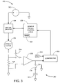
- FIG. 3 is a diagram of a preferred embodiment current control apparatus which can be used in the system of FIG. 1 .
- FIG. 4 is a graphical representation of a spindle motor start-up profile which can be used in the apparatus of FIG. 2 .
- FIG. 5 is a flowchart detailing a preferred embodiment current control method.
- FIG. 1 A disc drive 100 constructed in accordance with a preferred embodiment of the present invention is shown in FIG. 1 .
- the disc drive 100 includes a base 102 to which various components of the disc drive 100 are mounted.
- a top cover 104 shown partially cut away, cooperates with the base 102 to form an internal, sealed environment for the disc drive in a conventional manner.
- the components include a spindle motor 106 that rotates one or more discs 108 at a constant high speed. Information is written to and read from tracks on the discs 108 through the use of an actuator assembly 110 , which rotates during a seek operation about a bearing shaft assembly 112 positioned adjacent the discs 108 .
- the actuator assembly 110 includes a plurality of actuator arms 114 which extend towards the discs 108 , with one or more flexures 116 extending from each of the actuator arms 114 .
- a head 118 mounted at the distal end of each of the flexures 116 is a head 118 that includes an air bearing slider enabling the head 118 to fly in close proximity above the corresponding surface of the associated disc 108 .
- the track position of the heads 118 is controlled through the use of a voice coil motor (VCM) 124 , which typically includes a coil 126 attached to the actuator assembly 110 , as well as one or more permanent magnets 128 which establish a magnetic field in which the coil 126 is immersed.
- VCM voice coil motor
- the controlled application of current to the coil 126 causes magnetic interaction between the permanent magnets 128 and the coil 126 so that the coil 126 moves in accordance with the well-known Lorentz relationship.
- the actuator assembly 110 pivots about the bearing shaft assembly 112 , and the heads 118 are caused to move across the surfaces of the discs 108 .
- the spindle motor 106 is typically de-energized when the disc drive 100 is not in use for extended periods of time.
- the heads 118 are moved over park zones (not shown) near the inner diameter of the discs 108 when the drive motor is de-energized.
- the heads 118 are secured over the park zones (not shown) through the use of an actuator latch arrangement, which prevents inadvertent rotation of the actuator assembly 110 when the heads are parked.
- the heads 118 may alternatively be parked on ramps (not shown) at the outer diameter of the discs 108 when the drive motor is de-energized.
- a flex assembly 130 provides the requisite electrical connection paths for the actuator assembly 110 while allowing pivotal movement of the actuator assembly 110 during operation.
- the flex assembly includes a printed circuit board 132 to which head wires (not shown) are connected; the head wires being routed along the actuator arms 114 and the flexures 116 to the heads 118 .
- the printed circuit board 132 typically includes circuitry for controlling the write currents applied to the heads 118 during a write operation and a preamplifier for amplifying read signals generated by the heads 118 during a read operation.
- the flex assembly terminates at a flex bracket 134 for communication through the base deck 102 to a disc drive printed circuit board (not shown) mounted to the bottom side of the disc drive 100 .
- FIG. 2 provides a functional block diagram of the disc drive 100 .
- Data and host commands are provided from a host device to the disc drive 200 using interface circuitry 218 in conjunction with a top level control processor 220 .
- Data is transferred between the discs 208 and the host device using the interface circuitry 218 , a read/write channel 222 , a preamplifier circuit 224 , and a head 212 .
- Head positional control is provided by a closed-loop servo circuit 226 comprising demodulation circuitry 228 , a servo processor 230 (preferably comprising a digital signal processor, or DSP) and motor control circuitry 232 .
- the motor control circuitry 232 applies drive currents to the actuator coil 214 to rotate the actuator assembly 110 .
- the motor control circuitry 232 further applies drive signals to the spindle motor 206 to rotate the discs 208 .
- FIG. 3 provides a functional system diagram of relevant portions of the motor control circuitry 232 of FIG. 2 .
- FIG. 3 is also a system diagram of the preferred embodiment current control circuit 300 .
- the current control circuit 300 includes a power supply 302 which is provided by a host computer system (not shown).
- the power supply 302 powers a spindle motor 304 by way of motor drivers 320 .
- the motor drivers 320 are controlled by spindle driver control logic 322 with an associated programmable timer/counter circuit 324 .
- the voltage across current sensing resistor 306 is measured when the calibrating switch 314 is not enabled. Calibrating switch 314 may be enabled during the power-up procedure of a drive.
- the calibrating switch 314 provides a calibration reference signal for a ‘once at power-up’ calibration of the electronics from the digital-to-analog converter (DAC) 310 through comparator 318 .
- the ‘once at power-up’ calibration is achieved by applying a precision reference voltage (not shown) through the initiating switch 314 .
- This allows calibration of the DAC 310 by using a command from the DAC 310 to adjust the DAC 310 reference voltage input into the comparator 318 .
- a comparison can be made between the DAC 310 voltage input and the precision reference voltage by analyzing the comparator 318 output trip threshold.
- This calibration procedure can be used to eliminate offsets in the current control circuitry. Specifically, this calibration method can be used to measure offsets in the comparator 318 , the gain multiplier 308 , and the DAC 310 .
- gain multiplier 308 multiplies the voltage from the current sensing resistor 306 by a predetermined gain.
- switch 316 is closed, the output of the gain multiplier 308 is then applied to capacitor 312 , integrating the output of the gain multiplier 308 .
- the integrating capacitor 312 produces a voltage at its terminals proportional to the total current applied to the motor 304 .
- one-shot comparator 318 will fire a finite, programmable duration pulse which will disable motor drivers 320 and reset switch 316 .
- reset switch 316 discharges the capacitor 312 before the cycle repeats. After the finite programmable duration pulse time expires, the motor drivers are re-enabled and the process repeats.
- the charge in the capacitor 312 is measured by at least one input of voltage comparator 318 .
- DAC 310 supplies a reference voltage to another input of the voltage comparator 318 .
- the reference voltage from the DAC 310 is determined by a preprogrammed velocity dependent reference profile 400 as illustrated in FIG. 4 .
- the reference voltage from the DAC 310 does not need to be set to a specific reference profile, the reference voltage from the DAC 310 may be set to any value, such as a constant value or a time-dependent value.
- a velocity dependent reference profile 400 may be stored in memory (not shown) accessible by the DSP 230 .
- the motor control circuitry 232 includes circuitry (not shown) that measures the velocity of the discs 108 .
- DSP 230 transmits a data value to the DAC 310 where the data value corresponds to the preprogrammed velocity dependent reference profile 400 .
- the voltage comparator 318 is preferably a one-shot comparator which starts the programmable timer/counter circuit 324 to disable the motor drivers 320 when the voltage at the terminals of the capacitor 312 exceeds the voltage provided by the DAC 310 .
- the motor drivers 320 are then disabled for a programmed amount of time before the cycle repeats. The cycle is repeated by re-engaging the motor drivers 320 .
- FIG. 5 provides a flow chart for monitoring the start current or run current of the spindle motor 304 and the current drawn from the power supply 302 , generally illustrative of the steps carried out in accordance with preferred embodiments.
- the current controlling routine 500 is preferably executed each time the drive is brought from a deactivated to an operationally ready state.
- the current controlling routine 500 may also be implemented while the drive is in a run process.
- the routine starts at step 502 to initialize the start-up procedure for the spindle motor. This preferably includes providing power to the spindle motor from a rest state. The preferred embodiment also includes calibrating the circuitry and determining the initial setting for the reference profile 400 .
- step 502 the voltage of the current sensing resistor 306 is then measured in step 504 .
- the voltage from step 504 is then multiplied by a gain multiplier in step 505 .
- the multiplied voltage from step 505 is integrated in step 506 .
- the integration is preferably done using a capacitor 312 at the output of the gain multiplier 308 and at the input of the voltage comparator 318 .
- step 508 compares the integrated voltage to a reference voltage value. This is preferably done using a voltage comparator 218 and a DAC 310 with a preprogrammed reference voltage. If the integrated voltage value is less than the reference voltage value, then the routine will repeat back step 502 . If the integrated voltage value is greater than or equal to the reference voltage value then the process proceeds to step 510 .
- step 510 the process disables the motor drivers 320 . This is preferably done by sending a disable signal to the spindle driver control logic 322 .
- the routine proceeds with timing delay 512 .
- the routine counts the amount of time on step 512 until a preprogrammed time has passed.
- the process enables the motor drivers 320 in step 514 .
- Re-enabling the motor drivers 320 , step 514 may also include re-enabling voltage to the motor 304 .
- the process repeats back to the measure voltage step 504 .
- the measure voltage step 504 also includes monitoring the motor velocity and adjusting the DAC 310 reference voltage according to a velocity dependent reference profile, such as 400 .
- One advantage of the current control system 300 over other designs is that the amount of voltage and current drawn from the power supply is limited. Controlling the power supply in this manner reduces high frequency current spikes seen on the power supply due to motor commutation switching during spindle motor start-up.
- Another of the advantages of the current control system 300 over other types of designs is the use of the DAC 310 provides a programmable means for adjusting the reference voltage without having to place additional components on a circuit board. Using a DAC 310 provides the ability to have variations as to what type of reference voltage is used. The reference voltage may be determined by values such as constants, time dependent values, velocity dependent values, or any other value.
- a first contemplated embodiment of the present invention includes a method in which controlling the start-up power of a motor is monitored.
- the method comprises steps of initially applying power to a spindle motor to engage a start-up sequence (such as step 502 ). Thereafter, the amount of current applied to the spindle motor during the start-up sequence is monitored (such as step 504 ).
- the method also includes obtaining a control voltage proportional to the motor voltage and disabling the start-up sequence if the control voltage exceeds a predetermined voltage threshold (such as steps 505 and 508 ).
- the voltage threshold (such as step 508 ) is obtained from a digital-to-analog converter (such as 310 ).
- the voltage threshold corresponds to a preprogrammed start-up disc profile (such as 400 ).
- the method further preferably comprises obtaining the control voltage by integrating (such as step 506 ) a voltage across a current sensing resistor (such as 306 ). Further, the method preferably comprises a calibration procedure initialized by a calibration switch (such as 314 ).
- a second contemplated embodiment of the present invention includes a method for controlling the current drawn from a power supply in a computer system.
- the method comprises steps of initially applying power to a spindle motor to engage a start-up sequence (such as step 502 ). Thereafter, the amount of voltage applied to the spindle motor during the start-up sequence is monitored (such as step 504 ).
- the method also includes obtaining a control voltage proportional to the motor voltage and disabling the start-up sequence if the control voltage exceeds a predetermined voltage threshold (such as steps 505 and 508 ).
- the voltage threshold is obtained from a digital-to-analog converter (such as 310 ).
- the voltage threshold corresponds to a preprogrammed startup disc profile (such as 400 ).
- the method further preferably comprises obtaining the control voltage by integrating (such as step 506 ) a voltage across a current sensing resistor (such as 306 ). Further, the method preferably comprises a calibration procedure initialized by a calibration switch (such as 314 ).
- a third contemplated embodiment is a data storage device including at least one spindle motor, a power supply electrically coupled to the spindle motor (such as 302 ), and a spindle motor controller (such as 232 ).
- the spindle motor controller (such as 232 ) is operatively coupled to the spindle motor and the power supply so as to measure and limit an amount of power from the power supply that is utilized by the spindle motor during a spindle motor start-up sequence (such as 500 ) or a spindle motor run sequence.
- the data storage device includes a driver control function programmed into the motor controller so that a spindle motor driver (such as 320 ) may be disabled for a fixed period of time.
- the data storage device includes a data storage device controller (such as 220 ) which is operably coupled to the spindle motor controller (such as 232 ), the data storage device controller having the functionality to initiate or deactivate the spindle motor start-up sequence.
- a data storage device controller such as 220
- the spindle motor controller such as 232
- the data storage device controller having the functionality to initiate or deactivate the spindle motor start-up sequence.
- the driver control function disables the spindle motor drivers when a signal proportional to a current through the spindle motor exceeds a predetermined threshold.
- the predetermined threshold is a programmable voltage from a digital-to-analog converter (such as 310 ).
- Another contemplated embodiment of the present invention includes a method in which controlling the run power of a motor is monitored.
- the method comprises steps limiting the amount of current applied to the spindle motor during the run sequence (such as step 504 ).
- the method also includes obtaining a control voltage proportional to the motor voltage and disabling the run sequence if the control voltage exceeds a predetermined voltage threshold (such as steps 505 and 508 ).
- the voltage threshold (such as step 508 ) is obtained from a digital-to-analog converter (such as 310 ).
- the voltage threshold corresponds to a preprogrammed start-up disc profile (such as 400 ).
- the method further preferably comprises obtaining the control voltage by integrating (such as step 506 ) a voltage across a current sensing resistor (such as 306 ).
Landscapes
- Control Of Electric Motors In General (AREA)
- Rotational Drive Of Disk (AREA)
- Motor And Converter Starters (AREA)
- Control Of Motors That Do Not Use Commutators (AREA)
Abstract
Description
Claims (10)
Priority Applications (2)
| Application Number | Priority Date | Filing Date | Title |
|---|---|---|---|
| US09/995,206 US7692394B2 (en) | 2000-11-27 | 2001-11-27 | Power supply output control apparatus and method |
| US10/028,222 US6710567B2 (en) | 2000-11-27 | 2001-12-21 | Velocity dependent reference profile for spindle motor acceleration control |
Applications Claiming Priority (2)
| Application Number | Priority Date | Filing Date | Title |
|---|---|---|---|
| US25321600P | 2000-11-27 | 2000-11-27 | |
| US09/995,206 US7692394B2 (en) | 2000-11-27 | 2001-11-27 | Power supply output control apparatus and method |
Related Child Applications (1)
| Application Number | Title | Priority Date | Filing Date |
|---|---|---|---|
| US10/028,222 Continuation-In-Part US6710567B2 (en) | 2000-11-27 | 2001-12-21 | Velocity dependent reference profile for spindle motor acceleration control |
Publications (2)
| Publication Number | Publication Date |
|---|---|
| US20020079856A1 US20020079856A1 (en) | 2002-06-27 |
| US7692394B2 true US7692394B2 (en) | 2010-04-06 |
Family
ID=22959354
Family Applications (1)
| Application Number | Title | Priority Date | Filing Date |
|---|---|---|---|
| US09/995,206 Expired - Fee Related US7692394B2 (en) | 2000-11-27 | 2001-11-27 | Power supply output control apparatus and method |
Country Status (7)
| Country | Link |
|---|---|
| US (1) | US7692394B2 (en) |
| JP (1) | JP2004515188A (en) |
| KR (1) | KR20030070035A (en) |
| CN (1) | CN1503971A (en) |
| DE (1) | DE10196950T5 (en) |
| GB (1) | GB2387049A (en) |
| WO (1) | WO2002043064A2 (en) |
Cited By (4)
| Publication number | Priority date | Publication date | Assignee | Title |
|---|---|---|---|---|
| US20100165811A1 (en) * | 2008-12-30 | 2010-07-01 | Stmicrolectronics, Inc. | Management of disk drive during power loss |
| US20120169259A1 (en) * | 2011-01-03 | 2012-07-05 | Allen Michael Ritter | Method and system for power conversion |
| US9391544B2 (en) | 2008-11-18 | 2016-07-12 | Stmicroelectronics, Inc. | Asymmetrical driver |
| US11309824B2 (en) * | 2018-03-19 | 2022-04-19 | Tsubakimoto Chain Co. | Motor device |
Families Citing this family (6)
| Publication number | Priority date | Publication date | Assignee | Title |
|---|---|---|---|---|
| US6710567B2 (en) * | 2000-11-27 | 2004-03-23 | Seagate Technology Llc | Velocity dependent reference profile for spindle motor acceleration control |
| JP2004064971A (en) | 2002-07-31 | 2004-02-26 | Toshiba Corp | Disk storage device, spindle motor driver and spindle motor driving method applied to the disk storage device |
| KR100630713B1 (en) * | 2004-11-06 | 2006-10-02 | 삼성전자주식회사 | Spindle Motor Starting Current Control Method and Disk Drive Using the Same |
| US9202511B1 (en) | 2014-06-17 | 2015-12-01 | Seagate Technology Llc | Current-based environment determination |
| CN105577037B (en) * | 2014-10-31 | 2018-12-04 | 台达电子工业股份有限公司 | Fan starting control method and fan |
| JP2021034088A (en) * | 2019-08-28 | 2021-03-01 | 株式会社東芝 | Magnetic disk device and data protection method for the magnetic disk device |
Citations (83)
| Publication number | Priority date | Publication date | Assignee | Title |
|---|---|---|---|---|
| US3569807A (en) * | 1969-02-27 | 1971-03-09 | Nat Electro Mechanical Systems | Motor speed control system |
| US3670237A (en) * | 1969-12-23 | 1972-06-13 | Schubert & Salzer Maschinen | Apparatus for the smooth switching-on of an electrical load |
| US3972535A (en) * | 1974-11-08 | 1976-08-03 | Pertec Corporation | Spindle drive motor |
| US4410845A (en) * | 1981-10-01 | 1983-10-18 | Hughes Tool Company | Backspin detection circuit for a submersible pump |
| US4493001A (en) * | 1983-11-10 | 1985-01-08 | General Motors Corporation | Motor vehicle battery rundown protection system |
| US4547715A (en) * | 1984-07-09 | 1985-10-15 | Motorola, Inc. | Current control circuit |
| US4558264A (en) * | 1984-10-18 | 1985-12-10 | General Electric Company | Current control method and circuit for electronically-commutated motors |
| US4574228A (en) * | 1984-12-07 | 1986-03-04 | International Business Machines Corp. | Current controlled motor drive circuit |
| US4673851A (en) * | 1986-03-31 | 1987-06-16 | General Motors Corporation | PWM motor operating system with RFI suppression |
| US4682095A (en) * | 1985-06-20 | 1987-07-21 | Matsushita Electric Industrial Co. Ltd. | Circuit arrangement for controlling starting current of a motor |
| US4804901A (en) * | 1987-11-13 | 1989-02-14 | Kilo-Watt-Ch-Dog, Inc. | Motor starting circuit |
| US4893067A (en) * | 1987-05-06 | 1990-01-09 | Black & Decker Inc. | Direct current motor speed control |
| US4967291A (en) * | 1988-11-02 | 1990-10-30 | Miniscribe Corporation | Method and apparatus for preventing an over-velocity error condition of a hard disk drive system |
| US5017854A (en) * | 1990-10-29 | 1991-05-21 | Hughes Aircraft Company | Variable duty cycle pulse width modulated motor control system |
| US5028852A (en) * | 1990-06-21 | 1991-07-02 | Seagate Technology, Inc. | Position detection for a brushless DC motor without hall effect devices using a time differential method |
| US5117165A (en) | 1990-06-29 | 1992-05-26 | Seagate Technology, Inc. | Closed-loop control of a brushless DC motor from standstill to medium speed |
| US5179494A (en) * | 1989-04-18 | 1993-01-12 | Kabushiki Kaisha Toyoda Jidoshokki Seisakusho | Excess voltage protection apparatus for an electric vehicle |
| US5191269A (en) * | 1991-10-10 | 1993-03-02 | Sgs-Thomson Microelectronics, Inc. | Brushless direct current motor with minimized current ripple and method |
| US5245496A (en) * | 1991-08-16 | 1993-09-14 | Kim Nam H | Self-programming non-invasive motor overload prevention system |
| USRE34399E (en) | 1987-02-26 | 1993-10-05 | Micropolis Corporation | Winchester disk drive motor circuitry |
| US5254914A (en) * | 1990-06-29 | 1993-10-19 | Seagate Technology, Inc. | Position detection for a brushless DC motor without Hall effect devices using a mutual inductance detection method |
| US5278747A (en) * | 1990-09-14 | 1994-01-11 | Aktiebolaget Electrolux | DC/AC converter with overcurrent protection by temporary shutdown |
| US5293152A (en) * | 1992-02-10 | 1994-03-08 | Bussin George N | Vehicle ostacle detector and alarm system |
| US5339489A (en) * | 1992-02-28 | 1994-08-23 | Paul Journee, S.A. | Screen wiping apparatus with adjustable wiper force |
| US5412809A (en) | 1992-11-12 | 1995-05-02 | Mitsumi Electric Co., Ltd. | Disk drive power control circuit and method |
| US5457365A (en) | 1992-12-04 | 1995-10-10 | Integral Peripherals, Inc. | Disk drive power management system |
| US5457364A (en) | 1994-01-18 | 1995-10-10 | Allegro Microsystems, Inc. | Bridge motor driver with short-circuit protection and motor-current limiting feature |
| US5574608A (en) * | 1993-10-01 | 1996-11-12 | Matsushita Electric Industrial Co., Ltd. | Brushless motor lock detection apparatus |
| US5598071A (en) | 1994-07-11 | 1997-01-28 | Seagate Technology | Method for starting and commutating a permanent-magnet direct current motor having a single phase winding |
| US5612580A (en) * | 1995-10-10 | 1997-03-18 | Northrop Grumman Corporation | Uninterruptible power system |
| US5650705A (en) * | 1995-02-13 | 1997-07-22 | Hart; John Roger | Apparatus and method for controlling currents in an inductor |
| US5666066A (en) * | 1994-11-29 | 1997-09-09 | Samsung Electronics Co., Ltd. | Overcurrent detecting device for a DC motor |
| US5675230A (en) | 1994-03-01 | 1997-10-07 | Seagate Technology, Inc. | Method and apparatus for dynamic low voltage spindle motor operation |
| US5706222A (en) * | 1996-04-29 | 1998-01-06 | International Business Machines Corporation | Multiple mode peak detector |
| US5719732A (en) * | 1995-12-14 | 1998-02-17 | Tsubakimoto Chain Co. | Overload protecting device |
| US5767639A (en) * | 1995-07-14 | 1998-06-16 | Teac Corporation | Electronic control system for a brushless electric motor |
| US5821727A (en) * | 1996-04-16 | 1998-10-13 | Okuma Corporation | Induction motor control unit |
| US5825234A (en) | 1995-12-30 | 1998-10-20 | Samsung Electronics, Co., Ltd. | Switch-control integrated circuit |
| US5832324A (en) * | 1996-12-03 | 1998-11-03 | Olympus Optical Co., Ltd. | Power supply unit of camera |
| US5839092A (en) * | 1997-03-26 | 1998-11-17 | Square D Company | Arcing fault detection system using fluctuations in current peaks and waveforms |
| US5841252A (en) * | 1995-03-31 | 1998-11-24 | Seagate Technology, Inc. | Detection of starting motor position in a brushless DC motor |
| US5844388A (en) | 1996-03-29 | 1998-12-01 | Sgs-Thomson Microelectronics S.R.L. | Drive systems for a brushless motor employing predefined driving profiles stored in a nonvolatile memory |
| US5847523A (en) | 1995-05-25 | 1998-12-08 | Papst-Motoren Gmbh & Co. Kg | Method of limiting current in a DC motor and DC motor system for implementing said method |
| US5854731A (en) * | 1995-07-15 | 1998-12-29 | Smiths Industries Public Limited Company | Electrical apparatus |
| US5898296A (en) * | 1998-02-17 | 1999-04-27 | Lucent Technologies Inc. | Isolation regulator |
| US5910715A (en) * | 1995-03-30 | 1999-06-08 | Samsung Heavy Industries Co., Ltd. | Current control apparatus in DC motor |
| US5912543A (en) | 1995-11-16 | 1999-06-15 | Deutsche Thomson-Brandt Gmbh | Circuit having a digital controller for operation of a synchronous T motor |
| US5949121A (en) * | 1996-08-02 | 1999-09-07 | Motorola Inc. | Temperature-indicating field effect transistor |
| US5952817A (en) * | 1997-04-24 | 1999-09-14 | Linear Technology Corporation | Apparatus and method using waveform shaping for reducing high frequency noise from switching inductive loads |
| US5959817A (en) * | 1997-02-17 | 1999-09-28 | Robert Bosch | Control device for operating a wiper motor |
| US5959419A (en) | 1997-06-27 | 1999-09-28 | Aisin Seiki Kabushiki Kaisha | Energization controller of electric motor |
| US6008619A (en) * | 1997-06-30 | 1999-12-28 | Nec Corporation | Motor drive apparatus and motor driving method capable of simply reducing rotating speed in PWM mode |
| US6011375A (en) * | 1997-07-02 | 2000-01-04 | Seagate Technology, Inc. | Disc drive spindle motor with programmable current control |
| US6043631A (en) * | 1998-01-02 | 2000-03-28 | Total Battery Management, Inc. | Battery charger and method of charging rechargeable batteries |
| US6100656A (en) * | 1999-01-19 | 2000-08-08 | Quantum Corporation | Start-up algorithm for a brushless sensorless motor |
| US6124689A (en) * | 1999-03-26 | 2000-09-26 | Quantum Corporation | Trapezoidal spindle motor driver |
| US6148240A (en) * | 1998-03-06 | 2000-11-14 | Quantum Corporation | Method and apparatus for performing an open-loop current shaping for seeking acoustics reduction in a disk drive |
| US6150789A (en) * | 1999-02-13 | 2000-11-21 | Tri-Tech, Inc. | Stepper motor control |
| US6151200A (en) * | 1998-03-05 | 2000-11-21 | International Business Machines Corporation | Method of discharging SOI floating body charge |
| US6160368A (en) * | 1998-06-22 | 2000-12-12 | Western Digital Corporation | Faster spin-down operation in a disk drive by utilizing pulsed braking |
| US6166503A (en) * | 1997-11-26 | 2000-12-26 | Seagate Technology Llc | Disc drive spindle motor with programmable current control |
| US6166566A (en) | 1997-11-14 | 2000-12-26 | Linear Technology Corporation | Adaptive threshold circuit for comparators |
| US6198241B1 (en) * | 1999-07-07 | 2001-03-06 | Westinghouse Air Brake Company | Motor protection for a powered door system |
| US6204621B1 (en) | 1998-09-02 | 2001-03-20 | Matsushita Electric Industrial Co., Ltd. | Disk drive apparatus motor |
| US6205037B1 (en) | 1999-12-21 | 2001-03-20 | Thomson Licensing S.A. | Overload protection for a switch mode power supply |
| US6218794B1 (en) | 1998-10-28 | 2001-04-17 | International Business Machines Corporation | Spindle motor startup method and apparatus |
| US6233625B1 (en) | 1998-11-18 | 2001-05-15 | Compaq Computer Corporation | System and method for applying initialization power to SCSI devices |
| US6246651B1 (en) | 1997-11-07 | 2001-06-12 | Teac Corporation | Disk apparatus in which an improved current supply control is performed to effectively reduce a current consumption |
| US6252752B1 (en) * | 1999-02-05 | 2001-06-26 | Tsubakimoto Chain Co. | Overload protection apparatus and a speed reducer having such an apparatus |
| US6282046B1 (en) | 1998-09-04 | 2001-08-28 | International Business Machines Corporation | Current limiting in high performance files |
| US6285521B1 (en) | 1999-03-25 | 2001-09-04 | Western Digital Technologies, Inc. | Disk drive employing power source modulation for reducing power consumption |
| US6286108B1 (en) | 1990-07-13 | 2001-09-04 | Hitachi, Ltd. | Disk system and power-on sequence for the same |
| US6285149B1 (en) * | 1999-07-12 | 2001-09-04 | Agere Systems Guardian Corp. | Double sampled phase detector circuit |
| US6304409B1 (en) | 1999-06-30 | 2001-10-16 | Seagate Technology Llc | Active damping of actuator bearing translational mode |
| US6384554B1 (en) * | 1991-10-03 | 2002-05-07 | Papst Licensing Gmbh | Drive circuit for brushless DC motors |
| US6407523B1 (en) * | 2000-10-25 | 2002-06-18 | Jorgensen Conveyors, Inc. | Method and apparatus for controlling conveyor |
| US20030042858A1 (en) * | 2001-08-23 | 2003-03-06 | Weinbrenner Richard L. | Motor driver circuit to operate in limited power environment |
| US6577088B2 (en) | 2001-02-09 | 2003-06-10 | Seagate Technology Llc | Closed loop spindle motor acceleration control in a disc drive |
| US20030226987A1 (en) * | 2002-06-06 | 2003-12-11 | Gallmeyer Christopher F. | Method and apparatus for seat detection and soft seating in a piezoelectric device actuated valve system |
| US6667843B2 (en) * | 2001-03-01 | 2003-12-23 | Agere Systems Inc. | Integrated programmable error amplifier |
| US6710567B2 (en) | 2000-11-27 | 2004-03-23 | Seagate Technology Llc | Velocity dependent reference profile for spindle motor acceleration control |
| US6727670B1 (en) * | 2002-12-12 | 2004-04-27 | Ford Global Technologies, Llc | Battery current limiter for a high voltage battery pack in a hybrid electric vehicle powertrain |
| US20040189221A1 (en) * | 2003-03-27 | 2004-09-30 | Minoru Kurosawa | Drive control device for direct current motor, rotation drive system for direct current motor and semiconductor integrated circuit for driving coil |
-
2001
- 2001-11-27 CN CNA01819513XA patent/CN1503971A/en active Pending
- 2001-11-27 WO PCT/US2001/044354 patent/WO2002043064A2/en not_active Ceased
- 2001-11-27 JP JP2002544718A patent/JP2004515188A/en active Pending
- 2001-11-27 US US09/995,206 patent/US7692394B2/en not_active Expired - Fee Related
- 2001-11-27 GB GB0312599A patent/GB2387049A/en not_active Withdrawn
- 2001-11-27 DE DE10196950T patent/DE10196950T5/en not_active Withdrawn
- 2001-11-27 KR KR10-2003-7006817A patent/KR20030070035A/en not_active Ceased
Patent Citations (83)
| Publication number | Priority date | Publication date | Assignee | Title |
|---|---|---|---|---|
| US3569807A (en) * | 1969-02-27 | 1971-03-09 | Nat Electro Mechanical Systems | Motor speed control system |
| US3670237A (en) * | 1969-12-23 | 1972-06-13 | Schubert & Salzer Maschinen | Apparatus for the smooth switching-on of an electrical load |
| US3972535A (en) * | 1974-11-08 | 1976-08-03 | Pertec Corporation | Spindle drive motor |
| US4410845A (en) * | 1981-10-01 | 1983-10-18 | Hughes Tool Company | Backspin detection circuit for a submersible pump |
| US4493001A (en) * | 1983-11-10 | 1985-01-08 | General Motors Corporation | Motor vehicle battery rundown protection system |
| US4547715A (en) * | 1984-07-09 | 1985-10-15 | Motorola, Inc. | Current control circuit |
| US4558264A (en) * | 1984-10-18 | 1985-12-10 | General Electric Company | Current control method and circuit for electronically-commutated motors |
| US4574228A (en) * | 1984-12-07 | 1986-03-04 | International Business Machines Corp. | Current controlled motor drive circuit |
| US4682095A (en) * | 1985-06-20 | 1987-07-21 | Matsushita Electric Industrial Co. Ltd. | Circuit arrangement for controlling starting current of a motor |
| US4673851A (en) * | 1986-03-31 | 1987-06-16 | General Motors Corporation | PWM motor operating system with RFI suppression |
| USRE34399E (en) | 1987-02-26 | 1993-10-05 | Micropolis Corporation | Winchester disk drive motor circuitry |
| US4893067A (en) * | 1987-05-06 | 1990-01-09 | Black & Decker Inc. | Direct current motor speed control |
| US4804901A (en) * | 1987-11-13 | 1989-02-14 | Kilo-Watt-Ch-Dog, Inc. | Motor starting circuit |
| US4967291A (en) * | 1988-11-02 | 1990-10-30 | Miniscribe Corporation | Method and apparatus for preventing an over-velocity error condition of a hard disk drive system |
| US5179494A (en) * | 1989-04-18 | 1993-01-12 | Kabushiki Kaisha Toyoda Jidoshokki Seisakusho | Excess voltage protection apparatus for an electric vehicle |
| US5028852A (en) * | 1990-06-21 | 1991-07-02 | Seagate Technology, Inc. | Position detection for a brushless DC motor without hall effect devices using a time differential method |
| US5254914A (en) * | 1990-06-29 | 1993-10-19 | Seagate Technology, Inc. | Position detection for a brushless DC motor without Hall effect devices using a mutual inductance detection method |
| US5117165A (en) | 1990-06-29 | 1992-05-26 | Seagate Technology, Inc. | Closed-loop control of a brushless DC motor from standstill to medium speed |
| US6286108B1 (en) | 1990-07-13 | 2001-09-04 | Hitachi, Ltd. | Disk system and power-on sequence for the same |
| US5278747A (en) * | 1990-09-14 | 1994-01-11 | Aktiebolaget Electrolux | DC/AC converter with overcurrent protection by temporary shutdown |
| US5017854A (en) * | 1990-10-29 | 1991-05-21 | Hughes Aircraft Company | Variable duty cycle pulse width modulated motor control system |
| US5245496A (en) * | 1991-08-16 | 1993-09-14 | Kim Nam H | Self-programming non-invasive motor overload prevention system |
| US6384554B1 (en) * | 1991-10-03 | 2002-05-07 | Papst Licensing Gmbh | Drive circuit for brushless DC motors |
| US5191269A (en) * | 1991-10-10 | 1993-03-02 | Sgs-Thomson Microelectronics, Inc. | Brushless direct current motor with minimized current ripple and method |
| US5293152A (en) * | 1992-02-10 | 1994-03-08 | Bussin George N | Vehicle ostacle detector and alarm system |
| US5339489A (en) * | 1992-02-28 | 1994-08-23 | Paul Journee, S.A. | Screen wiping apparatus with adjustable wiper force |
| US5412809A (en) | 1992-11-12 | 1995-05-02 | Mitsumi Electric Co., Ltd. | Disk drive power control circuit and method |
| US5457365A (en) | 1992-12-04 | 1995-10-10 | Integral Peripherals, Inc. | Disk drive power management system |
| US5574608A (en) * | 1993-10-01 | 1996-11-12 | Matsushita Electric Industrial Co., Ltd. | Brushless motor lock detection apparatus |
| US5457364A (en) | 1994-01-18 | 1995-10-10 | Allegro Microsystems, Inc. | Bridge motor driver with short-circuit protection and motor-current limiting feature |
| US5675230A (en) | 1994-03-01 | 1997-10-07 | Seagate Technology, Inc. | Method and apparatus for dynamic low voltage spindle motor operation |
| US5598071A (en) | 1994-07-11 | 1997-01-28 | Seagate Technology | Method for starting and commutating a permanent-magnet direct current motor having a single phase winding |
| US5666066A (en) * | 1994-11-29 | 1997-09-09 | Samsung Electronics Co., Ltd. | Overcurrent detecting device for a DC motor |
| US5650705A (en) * | 1995-02-13 | 1997-07-22 | Hart; John Roger | Apparatus and method for controlling currents in an inductor |
| US5910715A (en) * | 1995-03-30 | 1999-06-08 | Samsung Heavy Industries Co., Ltd. | Current control apparatus in DC motor |
| US5841252A (en) * | 1995-03-31 | 1998-11-24 | Seagate Technology, Inc. | Detection of starting motor position in a brushless DC motor |
| US5847523A (en) | 1995-05-25 | 1998-12-08 | Papst-Motoren Gmbh & Co. Kg | Method of limiting current in a DC motor and DC motor system for implementing said method |
| US5767639A (en) * | 1995-07-14 | 1998-06-16 | Teac Corporation | Electronic control system for a brushless electric motor |
| US5854731A (en) * | 1995-07-15 | 1998-12-29 | Smiths Industries Public Limited Company | Electrical apparatus |
| US5612580A (en) * | 1995-10-10 | 1997-03-18 | Northrop Grumman Corporation | Uninterruptible power system |
| US5912543A (en) | 1995-11-16 | 1999-06-15 | Deutsche Thomson-Brandt Gmbh | Circuit having a digital controller for operation of a synchronous T motor |
| US5719732A (en) * | 1995-12-14 | 1998-02-17 | Tsubakimoto Chain Co. | Overload protecting device |
| US5825234A (en) | 1995-12-30 | 1998-10-20 | Samsung Electronics, Co., Ltd. | Switch-control integrated circuit |
| US5844388A (en) | 1996-03-29 | 1998-12-01 | Sgs-Thomson Microelectronics S.R.L. | Drive systems for a brushless motor employing predefined driving profiles stored in a nonvolatile memory |
| US5821727A (en) * | 1996-04-16 | 1998-10-13 | Okuma Corporation | Induction motor control unit |
| US5706222A (en) * | 1996-04-29 | 1998-01-06 | International Business Machines Corporation | Multiple mode peak detector |
| US5949121A (en) * | 1996-08-02 | 1999-09-07 | Motorola Inc. | Temperature-indicating field effect transistor |
| US5832324A (en) * | 1996-12-03 | 1998-11-03 | Olympus Optical Co., Ltd. | Power supply unit of camera |
| US5959817A (en) * | 1997-02-17 | 1999-09-28 | Robert Bosch | Control device for operating a wiper motor |
| US5839092A (en) * | 1997-03-26 | 1998-11-17 | Square D Company | Arcing fault detection system using fluctuations in current peaks and waveforms |
| US5952817A (en) * | 1997-04-24 | 1999-09-14 | Linear Technology Corporation | Apparatus and method using waveform shaping for reducing high frequency noise from switching inductive loads |
| US5959419A (en) | 1997-06-27 | 1999-09-28 | Aisin Seiki Kabushiki Kaisha | Energization controller of electric motor |
| US6008619A (en) * | 1997-06-30 | 1999-12-28 | Nec Corporation | Motor drive apparatus and motor driving method capable of simply reducing rotating speed in PWM mode |
| US6011375A (en) * | 1997-07-02 | 2000-01-04 | Seagate Technology, Inc. | Disc drive spindle motor with programmable current control |
| US6246651B1 (en) | 1997-11-07 | 2001-06-12 | Teac Corporation | Disk apparatus in which an improved current supply control is performed to effectively reduce a current consumption |
| US6166566A (en) | 1997-11-14 | 2000-12-26 | Linear Technology Corporation | Adaptive threshold circuit for comparators |
| US6166503A (en) * | 1997-11-26 | 2000-12-26 | Seagate Technology Llc | Disc drive spindle motor with programmable current control |
| US6043631A (en) * | 1998-01-02 | 2000-03-28 | Total Battery Management, Inc. | Battery charger and method of charging rechargeable batteries |
| US5898296A (en) * | 1998-02-17 | 1999-04-27 | Lucent Technologies Inc. | Isolation regulator |
| US6151200A (en) * | 1998-03-05 | 2000-11-21 | International Business Machines Corporation | Method of discharging SOI floating body charge |
| US6148240A (en) * | 1998-03-06 | 2000-11-14 | Quantum Corporation | Method and apparatus for performing an open-loop current shaping for seeking acoustics reduction in a disk drive |
| US6160368A (en) * | 1998-06-22 | 2000-12-12 | Western Digital Corporation | Faster spin-down operation in a disk drive by utilizing pulsed braking |
| US6204621B1 (en) | 1998-09-02 | 2001-03-20 | Matsushita Electric Industrial Co., Ltd. | Disk drive apparatus motor |
| US6282046B1 (en) | 1998-09-04 | 2001-08-28 | International Business Machines Corporation | Current limiting in high performance files |
| US6218794B1 (en) | 1998-10-28 | 2001-04-17 | International Business Machines Corporation | Spindle motor startup method and apparatus |
| US6233625B1 (en) | 1998-11-18 | 2001-05-15 | Compaq Computer Corporation | System and method for applying initialization power to SCSI devices |
| US6100656A (en) * | 1999-01-19 | 2000-08-08 | Quantum Corporation | Start-up algorithm for a brushless sensorless motor |
| US6252752B1 (en) * | 1999-02-05 | 2001-06-26 | Tsubakimoto Chain Co. | Overload protection apparatus and a speed reducer having such an apparatus |
| US6150789A (en) * | 1999-02-13 | 2000-11-21 | Tri-Tech, Inc. | Stepper motor control |
| US6285521B1 (en) | 1999-03-25 | 2001-09-04 | Western Digital Technologies, Inc. | Disk drive employing power source modulation for reducing power consumption |
| US6124689A (en) * | 1999-03-26 | 2000-09-26 | Quantum Corporation | Trapezoidal spindle motor driver |
| US6304409B1 (en) | 1999-06-30 | 2001-10-16 | Seagate Technology Llc | Active damping of actuator bearing translational mode |
| US6198241B1 (en) * | 1999-07-07 | 2001-03-06 | Westinghouse Air Brake Company | Motor protection for a powered door system |
| US6285149B1 (en) * | 1999-07-12 | 2001-09-04 | Agere Systems Guardian Corp. | Double sampled phase detector circuit |
| US6205037B1 (en) | 1999-12-21 | 2001-03-20 | Thomson Licensing S.A. | Overload protection for a switch mode power supply |
| US6407523B1 (en) * | 2000-10-25 | 2002-06-18 | Jorgensen Conveyors, Inc. | Method and apparatus for controlling conveyor |
| US6710567B2 (en) | 2000-11-27 | 2004-03-23 | Seagate Technology Llc | Velocity dependent reference profile for spindle motor acceleration control |
| US6577088B2 (en) | 2001-02-09 | 2003-06-10 | Seagate Technology Llc | Closed loop spindle motor acceleration control in a disc drive |
| US6667843B2 (en) * | 2001-03-01 | 2003-12-23 | Agere Systems Inc. | Integrated programmable error amplifier |
| US20030042858A1 (en) * | 2001-08-23 | 2003-03-06 | Weinbrenner Richard L. | Motor driver circuit to operate in limited power environment |
| US20030226987A1 (en) * | 2002-06-06 | 2003-12-11 | Gallmeyer Christopher F. | Method and apparatus for seat detection and soft seating in a piezoelectric device actuated valve system |
| US6727670B1 (en) * | 2002-12-12 | 2004-04-27 | Ford Global Technologies, Llc | Battery current limiter for a high voltage battery pack in a hybrid electric vehicle powertrain |
| US20040189221A1 (en) * | 2003-03-27 | 2004-09-30 | Minoru Kurosawa | Drive control device for direct current motor, rotation drive system for direct current motor and semiconductor integrated circuit for driving coil |
Cited By (8)
| Publication number | Priority date | Publication date | Assignee | Title |
|---|---|---|---|---|
| US9391544B2 (en) | 2008-11-18 | 2016-07-12 | Stmicroelectronics, Inc. | Asymmetrical driver |
| US10256751B2 (en) | 2008-11-18 | 2019-04-09 | Stmicroelectronics, Inc. | Asymmetrical driver |
| US20100165811A1 (en) * | 2008-12-30 | 2010-07-01 | Stmicrolectronics, Inc. | Management of disk drive during power loss |
| US8471509B2 (en) * | 2008-12-30 | 2013-06-25 | Stmicroelectronics, Inc. | Management of disk drive during power loss |
| US20120169259A1 (en) * | 2011-01-03 | 2012-07-05 | Allen Michael Ritter | Method and system for power conversion |
| US8736207B2 (en) * | 2011-01-03 | 2014-05-27 | General Electric Company | Method and system for power conversion |
| US9520808B2 (en) | 2011-01-03 | 2016-12-13 | General Electric Company | Method and system for power conversion |
| US11309824B2 (en) * | 2018-03-19 | 2022-04-19 | Tsubakimoto Chain Co. | Motor device |
Also Published As
| Publication number | Publication date |
|---|---|
| KR20030070035A (en) | 2003-08-27 |
| WO2002043064A2 (en) | 2002-05-30 |
| US20020079856A1 (en) | 2002-06-27 |
| WO2002043064A3 (en) | 2002-10-31 |
| DE10196950T5 (en) | 2004-07-22 |
| JP2004515188A (en) | 2004-05-20 |
| CN1503971A (en) | 2004-06-09 |
| GB2387049A (en) | 2003-10-01 |
| GB0312599D0 (en) | 2003-07-09 |
Similar Documents
| Publication | Publication Date | Title |
|---|---|---|
| US7573670B1 (en) | Disk drive seeking to OD track and then ramping velocity to implement fast unload | |
| US6396652B1 (en) | Apparatus and method for control head unloading on power down in a disk drive | |
| US6122131A (en) | Adaptively-controlled disk drive assembly | |
| US6867944B1 (en) | Disk drive comprising VCM stall detector for velocity control of an actuator arm | |
| JP2902921B2 (en) | Disk device temperature detection / control method | |
| US6735540B2 (en) | Sigma-delta ramp loading calibration | |
| EP1207520B1 (en) | Method and apparatus for improving cold temperature performance of a disk drive | |
| KR0182952B1 (en) | Recording current control circuit for a magnetic disk equipment and optimizing method therefor | |
| US7692394B2 (en) | Power supply output control apparatus and method | |
| USRE43863E1 (en) | Transitioning from startup code to application code during initialization of a processor based device | |
| WO1998057323A1 (en) | Temperature dependent disc drive parametric configuration | |
| US20010019463A1 (en) | Head loading and unloading method and device | |
| US6377417B1 (en) | Method for controlling repeatable runout compensation algorithm | |
| US6560057B1 (en) | Head positioning system for a disk drive during a power down condition | |
| US7576939B2 (en) | Discontinuous mode back EMF measurement | |
| US6995946B2 (en) | Temperature compensation of seek profiles in data storage devices | |
| US7005820B2 (en) | Apparatus for spindle bearing friction estimation for reliable disk drive startup | |
| US7023641B2 (en) | Recording current control method and magnetic disk drive | |
| JP2001169583A (en) | Ramp loading method and apparatus in hard disk drive using pulse width modulation | |
| US7558017B2 (en) | Magnetic disk drive and a loading/unloading method | |
| US7009354B2 (en) | Method for spindle bearing friction estimation for reliable disk drive startup operation | |
| US6072652A (en) | Technique for detecting stiction error in hard disk drive | |
| KR100422058B1 (en) | System, method, and program media for controlling commutation of disk drive motor | |
| US8988811B1 (en) | Disk drive toggling VCM inductor compensation to reduce acoustic noise | |
| JP2001067765A (en) | Magnetic disk drive and control method therefor |
Legal Events
| Date | Code | Title | Description |
|---|---|---|---|
| AS | Assignment |
Owner name: SEAGATE TECHNOLOGY LLC, CALIFORNIA Free format text: ASSIGNMENT OF ASSIGNORS INTEREST;ASSIGNORS:HILL, CHRISTOPHER L.;KORBEL, GARRY E.;REEL/FRAME:012329/0123 Effective date: 20011127 Owner name: SEAGATE TECHNOLOGY LLC,CALIFORNIA Free format text: ASSIGNMENT OF ASSIGNORS INTEREST;ASSIGNORS:HILL, CHRISTOPHER L.;KORBEL, GARRY E.;REEL/FRAME:012329/0123 Effective date: 20011127 |
|
| AS | Assignment |
Owner name: JPMORGAN CHASE BANK, AS COLLATERAL AGENT, NEW YORK Free format text: SECURITY AGREEMENT;ASSIGNOR:SEAGATE TECHNOLOGY LLC;REEL/FRAME:013177/0001 Effective date: 20020513 Owner name: JPMORGAN CHASE BANK, AS COLLATERAL AGENT,NEW YORK Free format text: SECURITY AGREEMENT;ASSIGNOR:SEAGATE TECHNOLOGY LLC;REEL/FRAME:013177/0001 Effective date: 20020513 |
|
| AS | Assignment |
Owner name: SEAGATE TECHNOLOGY LLC,CALIFORNIA Free format text: RELEASE OF SECURITY INTERESTS IN PATENT RIGHTS;ASSIGNOR:JPMORGAN CHASE BANK, N.A., AS ADMINISTRATIVE AGENT (FORMERLY KNOWN AS THE CHASE MANHATTAN BANK AND JPMORGAN CHASE BANK);REEL/FRAME:016926/0342 Effective date: 20051130 Owner name: SEAGATE TECHNOLOGY LLC, CALIFORNIA Free format text: RELEASE OF SECURITY INTERESTS IN PATENT RIGHTS;ASSIGNOR:JPMORGAN CHASE BANK, N.A., AS ADMINISTRATIVE AGENT (FORMERLY KNOWN AS THE CHASE MANHATTAN BANK AND JPMORGAN CHASE BANK);REEL/FRAME:016926/0342 Effective date: 20051130 |
|
| AS | Assignment |
Owner name: WELLS FARGO BANK, NATIONAL ASSOCIATION, AS COLLATERAL AGENT AND SECOND PRIORITY REPRESENTATIVE, CALIFORNIA Free format text: SECURITY AGREEMENT;ASSIGNORS:MAXTOR CORPORATION;SEAGATE TECHNOLOGY LLC;SEAGATE TECHNOLOGY INTERNATIONAL;REEL/FRAME:022757/0017 Effective date: 20090507 Owner name: JPMORGAN CHASE BANK, N.A., AS ADMINISTRATIVE AGENT AND FIRST PRIORITY REPRESENTATIVE, NEW YORK Free format text: SECURITY AGREEMENT;ASSIGNORS:MAXTOR CORPORATION;SEAGATE TECHNOLOGY LLC;SEAGATE TECHNOLOGY INTERNATIONAL;REEL/FRAME:022757/0017 Effective date: 20090507 Owner name: JPMORGAN CHASE BANK, N.A., AS ADMINISTRATIVE AGENT Free format text: SECURITY AGREEMENT;ASSIGNORS:MAXTOR CORPORATION;SEAGATE TECHNOLOGY LLC;SEAGATE TECHNOLOGY INTERNATIONAL;REEL/FRAME:022757/0017 Effective date: 20090507 Owner name: WELLS FARGO BANK, NATIONAL ASSOCIATION, AS COLLATE Free format text: SECURITY AGREEMENT;ASSIGNORS:MAXTOR CORPORATION;SEAGATE TECHNOLOGY LLC;SEAGATE TECHNOLOGY INTERNATIONAL;REEL/FRAME:022757/0017 Effective date: 20090507 |
|
| STCF | Information on status: patent grant |
Free format text: PATENTED CASE |
|
| AS | Assignment |
Owner name: SEAGATE TECHNOLOGY INTERNATIONAL, CALIFORNIA Free format text: RELEASE;ASSIGNOR:JPMORGAN CHASE BANK, N.A., AS ADMINISTRATIVE AGENT;REEL/FRAME:025662/0001 Effective date: 20110114 Owner name: SEAGATE TECHNOLOGY LLC, CALIFORNIA Free format text: RELEASE;ASSIGNOR:JPMORGAN CHASE BANK, N.A., AS ADMINISTRATIVE AGENT;REEL/FRAME:025662/0001 Effective date: 20110114 Owner name: SEAGATE TECHNOLOGY HDD HOLDINGS, CALIFORNIA Free format text: RELEASE;ASSIGNOR:JPMORGAN CHASE BANK, N.A., AS ADMINISTRATIVE AGENT;REEL/FRAME:025662/0001 Effective date: 20110114 Owner name: MAXTOR CORPORATION, CALIFORNIA Free format text: RELEASE;ASSIGNOR:JPMORGAN CHASE BANK, N.A., AS ADMINISTRATIVE AGENT;REEL/FRAME:025662/0001 Effective date: 20110114 |
|
| AS | Assignment |
Owner name: THE BANK OF NOVA SCOTIA, AS ADMINISTRATIVE AGENT, CANADA Free format text: SECURITY AGREEMENT;ASSIGNOR:SEAGATE TECHNOLOGY LLC;REEL/FRAME:026010/0350 Effective date: 20110118 Owner name: THE BANK OF NOVA SCOTIA, AS ADMINISTRATIVE AGENT, Free format text: SECURITY AGREEMENT;ASSIGNOR:SEAGATE TECHNOLOGY LLC;REEL/FRAME:026010/0350 Effective date: 20110118 |
|
| AS | Assignment |
Owner name: EVAULT INC. (F/K/A I365 INC.), CALIFORNIA Free format text: TERMINATION AND RELEASE OF SECURITY INTEREST IN PATENT RIGHTS;ASSIGNOR:WELLS FARGO BANK, NATIONAL ASSOCIATION, AS COLLATERAL AGENT AND SECOND PRIORITY REPRESENTATIVE;REEL/FRAME:030833/0001 Effective date: 20130312 Owner name: SEAGATE TECHNOLOGY INTERNATIONAL, CAYMAN ISLANDS Free format text: TERMINATION AND RELEASE OF SECURITY INTEREST IN PATENT RIGHTS;ASSIGNOR:WELLS FARGO BANK, NATIONAL ASSOCIATION, AS COLLATERAL AGENT AND SECOND PRIORITY REPRESENTATIVE;REEL/FRAME:030833/0001 Effective date: 20130312 Owner name: SEAGATE TECHNOLOGY LLC, CALIFORNIA Free format text: TERMINATION AND RELEASE OF SECURITY INTEREST IN PATENT RIGHTS;ASSIGNOR:WELLS FARGO BANK, NATIONAL ASSOCIATION, AS COLLATERAL AGENT AND SECOND PRIORITY REPRESENTATIVE;REEL/FRAME:030833/0001 Effective date: 20130312 Owner name: SEAGATE TECHNOLOGY US HOLDINGS, INC., CALIFORNIA Free format text: TERMINATION AND RELEASE OF SECURITY INTEREST IN PATENT RIGHTS;ASSIGNOR:WELLS FARGO BANK, NATIONAL ASSOCIATION, AS COLLATERAL AGENT AND SECOND PRIORITY REPRESENTATIVE;REEL/FRAME:030833/0001 Effective date: 20130312 |
|
| FPAY | Fee payment |
Year of fee payment: 4 |
|
| MAFP | Maintenance fee payment |
Free format text: PAYMENT OF MAINTENANCE FEE, 8TH YEAR, LARGE ENTITY (ORIGINAL EVENT CODE: M1552) Year of fee payment: 8 |
|
| FEPP | Fee payment procedure |
Free format text: MAINTENANCE FEE REMINDER MAILED (ORIGINAL EVENT CODE: REM.); ENTITY STATUS OF PATENT OWNER: LARGE ENTITY |
|
| LAPS | Lapse for failure to pay maintenance fees |
Free format text: PATENT EXPIRED FOR FAILURE TO PAY MAINTENANCE FEES (ORIGINAL EVENT CODE: EXP.); ENTITY STATUS OF PATENT OWNER: LARGE ENTITY |
|
| STCH | Information on status: patent discontinuation |
Free format text: PATENT EXPIRED DUE TO NONPAYMENT OF MAINTENANCE FEES UNDER 37 CFR 1.362 |
|
| FP | Lapsed due to failure to pay maintenance fee |
Effective date: 20220406 |
|
| AS | Assignment |
Owner name: SEAGATE TECHNOLOGY PUBLIC LIMITED COMPANY, CALIFORNIA Free format text: RELEASE BY SECURED PARTY;ASSIGNOR:THE BANK OF NOVA SCOTIA;REEL/FRAME:072193/0001 Effective date: 20250303 Owner name: SEAGATE TECHNOLOGY, CALIFORNIA Free format text: RELEASE BY SECURED PARTY;ASSIGNOR:THE BANK OF NOVA SCOTIA;REEL/FRAME:072193/0001 Effective date: 20250303 Owner name: SEAGATE TECHNOLOGY HDD HOLDINGS, CALIFORNIA Free format text: RELEASE BY SECURED PARTY;ASSIGNOR:THE BANK OF NOVA SCOTIA;REEL/FRAME:072193/0001 Effective date: 20250303 Owner name: I365 INC., CALIFORNIA Free format text: RELEASE BY SECURED PARTY;ASSIGNOR:THE BANK OF NOVA SCOTIA;REEL/FRAME:072193/0001 Effective date: 20250303 Owner name: SEAGATE TECHNOLOGY LLC, CALIFORNIA Free format text: RELEASE BY SECURED PARTY;ASSIGNOR:THE BANK OF NOVA SCOTIA;REEL/FRAME:072193/0001 Effective date: 20250303 Owner name: SEAGATE TECHNOLOGY INTERNATIONAL, CAYMAN ISLANDS Free format text: RELEASE BY SECURED PARTY;ASSIGNOR:THE BANK OF NOVA SCOTIA;REEL/FRAME:072193/0001 Effective date: 20250303 Owner name: SEAGATE HDD CAYMAN, CAYMAN ISLANDS Free format text: RELEASE BY SECURED PARTY;ASSIGNOR:THE BANK OF NOVA SCOTIA;REEL/FRAME:072193/0001 Effective date: 20250303 Owner name: SEAGATE TECHNOLOGY (US) HOLDINGS, INC., CALIFORNIA Free format text: RELEASE BY SECURED PARTY;ASSIGNOR:THE BANK OF NOVA SCOTIA;REEL/FRAME:072193/0001 Effective date: 20250303 Owner name: SEAGATE TECHNOLOGY PUBLIC LIMITED COMPANY, CALIFORNIA Free format text: RELEASE OF SECURITY INTEREST;ASSIGNOR:THE BANK OF NOVA SCOTIA;REEL/FRAME:072193/0001 Effective date: 20250303 Owner name: SEAGATE TECHNOLOGY, CALIFORNIA Free format text: RELEASE OF SECURITY INTEREST;ASSIGNOR:THE BANK OF NOVA SCOTIA;REEL/FRAME:072193/0001 Effective date: 20250303 Owner name: SEAGATE TECHNOLOGY HDD HOLDINGS, CALIFORNIA Free format text: RELEASE OF SECURITY INTEREST;ASSIGNOR:THE BANK OF NOVA SCOTIA;REEL/FRAME:072193/0001 Effective date: 20250303 Owner name: I365 INC., CALIFORNIA Free format text: RELEASE OF SECURITY INTEREST;ASSIGNOR:THE BANK OF NOVA SCOTIA;REEL/FRAME:072193/0001 Effective date: 20250303 Owner name: SEAGATE TECHNOLOGY LLC, CALIFORNIA Free format text: RELEASE OF SECURITY INTEREST;ASSIGNOR:THE BANK OF NOVA SCOTIA;REEL/FRAME:072193/0001 Effective date: 20250303 Owner name: SEAGATE TECHNOLOGY INTERNATIONAL, CAYMAN ISLANDS Free format text: RELEASE OF SECURITY INTEREST;ASSIGNOR:THE BANK OF NOVA SCOTIA;REEL/FRAME:072193/0001 Effective date: 20250303 Owner name: SEAGATE HDD CAYMAN, CAYMAN ISLANDS Free format text: RELEASE OF SECURITY INTEREST;ASSIGNOR:THE BANK OF NOVA SCOTIA;REEL/FRAME:072193/0001 Effective date: 20250303 Owner name: SEAGATE TECHNOLOGY (US) HOLDINGS, INC., CALIFORNIA Free format text: RELEASE OF SECURITY INTEREST;ASSIGNOR:THE BANK OF NOVA SCOTIA;REEL/FRAME:072193/0001 Effective date: 20250303 |