US7686295B2 - Paper ejecting device - Google Patents
Paper ejecting device Download PDFInfo
- Publication number
- US7686295B2 US7686295B2 US12/357,475 US35747509A US7686295B2 US 7686295 B2 US7686295 B2 US 7686295B2 US 35747509 A US35747509 A US 35747509A US 7686295 B2 US7686295 B2 US 7686295B2
- Authority
- US
- United States
- Prior art keywords
- paper
- sheet
- suction
- transport
- paper transport
- Prior art date
- Legal status (The legal status is an assumption and is not a legal conclusion. Google has not performed a legal analysis and makes no representation as to the accuracy of the status listed.)
- Expired - Fee Related
Links
- 230000009191 jumping Effects 0.000 claims description 67
- 239000003638 chemical reducing agent Substances 0.000 claims description 24
- 238000007664 blowing Methods 0.000 claims description 10
- 230000032258 transport Effects 0.000 description 147
- 238000007639 printing Methods 0.000 description 18
- 230000007246 mechanism Effects 0.000 description 6
- 239000007788 liquid Substances 0.000 description 4
- 230000007723 transport mechanism Effects 0.000 description 3
- 238000003854 Surface Print Methods 0.000 description 2
- 239000002783 friction material Substances 0.000 description 2
- 238000000034 method Methods 0.000 description 2
- 229920001343 polytetrafluoroethylene Polymers 0.000 description 2
- 239000004810 polytetrafluoroethylene Substances 0.000 description 2
- 238000005096 rolling process Methods 0.000 description 2
- XLYOFNOQVPJJNP-UHFFFAOYSA-N water Substances O XLYOFNOQVPJJNP-UHFFFAOYSA-N 0.000 description 2
- 241000252254 Catostomidae Species 0.000 description 1
- 239000011248 coating agent Substances 0.000 description 1
- 238000000576 coating method Methods 0.000 description 1
- 238000007641 inkjet printing Methods 0.000 description 1
- -1 polytetrafluoroethylene Polymers 0.000 description 1
- 239000000843 powder Substances 0.000 description 1
- 239000011347 resin Substances 0.000 description 1
- 229920005989 resin Polymers 0.000 description 1
- 238000005507 spraying Methods 0.000 description 1
- 239000007762 w/o emulsion Substances 0.000 description 1
- 230000037303 wrinkles Effects 0.000 description 1
Images


Classifications
-
- B—PERFORMING OPERATIONS; TRANSPORTING
- B65—CONVEYING; PACKING; STORING; HANDLING THIN OR FILAMENTARY MATERIAL
- B65H—HANDLING THIN OR FILAMENTARY MATERIAL, e.g. SHEETS, WEBS, CABLES
- B65H29/00—Delivering or advancing articles from machines; Advancing articles to or into piles
- B65H29/24—Delivering or advancing articles from machines; Advancing articles to or into piles by air blast or suction apparatus
- B65H29/241—Suction devices
- B65H29/242—Suction bands or belts
-
- B—PERFORMING OPERATIONS; TRANSPORTING
- B65—CONVEYING; PACKING; STORING; HANDLING THIN OR FILAMENTARY MATERIAL
- B65H—HANDLING THIN OR FILAMENTARY MATERIAL, e.g. SHEETS, WEBS, CABLES
- B65H2301/00—Handling processes for sheets or webs
- B65H2301/40—Type of handling process
- B65H2301/42—Piling, depiling, handling piles
- B65H2301/421—Forming a pile
- B65H2301/4212—Forming a pile of articles substantially horizontal
-
- B—PERFORMING OPERATIONS; TRANSPORTING
- B65—CONVEYING; PACKING; STORING; HANDLING THIN OR FILAMENTARY MATERIAL
- B65H—HANDLING THIN OR FILAMENTARY MATERIAL, e.g. SHEETS, WEBS, CABLES
- B65H2301/00—Handling processes for sheets or webs
- B65H2301/50—Auxiliary process performed during handling process
- B65H2301/51—Modifying a characteristic of handled material
- B65H2301/512—Changing form of handled material
- B65H2301/5125—Restoring form
- B65H2301/51256—Removing waviness or curl, smoothing
-
- B—PERFORMING OPERATIONS; TRANSPORTING
- B65—CONVEYING; PACKING; STORING; HANDLING THIN OR FILAMENTARY MATERIAL
- B65H—HANDLING THIN OR FILAMENTARY MATERIAL, e.g. SHEETS, WEBS, CABLES
- B65H2801/00—Application field
- B65H2801/03—Image reproduction devices
- B65H2801/18—Stencil printing machines
Definitions
- the present invention relates to a paper ejecting device for ejecting sheets of paper from a machine such as a stencil duplicator to a paper receiving tray and the like, and relates to a technique for correcting curling of the sheets during ejection.
- water-in-oil emulsion ink containing oil components has been mainly used for stencil duplicators and water based ink containing few oil components has been mainly used for ink-jet printers.
- a printed sheet is generally rolled from a surface on which liquid ink is printed to the opposite surface.
- the printed sheet is ejected to a paper receiving tray with the printed surface directed upward, the sheet is curled into a reversed U-shape from the front side, which is directed upward, to the back side.
- the printed sheet is rolled from a surface having a large print rate to the other surface having a small print rate.
- the printed sheet is curled downward into a reversed U-shape from the front side, which is directed upward, to the back side of the sheet when the front side has a higher surface print rate.
- the printed sheet is curled upward into a U-shape from the back side, which is directed downward, to the front side of the sheet when the back side has a higher print rate.
- a stencil duplicator of the prior art printed sheets of paper are transported by a paper suction transport belt and are ejected from a paper ejecting device to a paper receiving tray according to a typical technique.
- the paper ejecting device includes so-called jumping boards for adjusting the shape of a printed and ejected sheet, which jumps from the paper ejecting device to the paper receiving tray, to a predetermined shape. With the jumping boards, the shape of the printed sheet is curved so as to raise the sheet ends provided in parallel with an axis disposed along a jumping direction.
- the printed sheet is curled into a reversed U-shape (downward)
- the printed sheet is sucked by the paper suction transport belt and the surfaces of the printed sheet are shaped along a paper transport surface, so that curling of the sheet can be corrected.
- curling of the printed sheet is inverted and corrected and the shape of the printed and ejected sheet can be adjusted to a predetermined shape.
- the surfaces of the printed sheet cannot be shaped along the paper transport surfaces only by sucking the printed sheet by the paper suction transport belt.
- a paper transport unit for transporting sheets by air suction includes paper stiffness plates (corresponding to the jumping boards) for providing stiffness for a printed sheet which is ejected from a printer, and the paper transport surfaces of the paper stiffness plates have air suction holes for sucking the sheet on the transport surfaces.
- An object of the present invention is to provide a paper ejecting device which can positively correct curling, reduce friction on a paper transport surface to obtain smooth ejection, and adjust the shape of a printed and ejected sheet to a predetermined shape when the printed sheet is curled into a reversed U-shape (downward) and when the printed sheet is curled into a U-shape (upward).
- a paper ejecting device of the present invention includes a body having suction transport belts for transporting a sheet of paper along the paper transport surface of the body by suction; jumping boards provided on both sides of the body along a paper transport direction; and a curling corrector for correcting the shape of the sheet along the paper transport surfaces of the jumping boards.
- the jumping board has a friction reducer on the paper transport surface, the friction reducer reducing friction with the sheet.
- the curling corrector is made up of a sucker for sucking the sheet on the paper transport surface of the jumping board.
- the friction reducer is made up of a low-friction member composing the paper transport surface of the jumping board.
- the friction reducer is made up of a plurality of protrusions formed on the paper transport surface of the jumping board or is made up of concave and convex portions formed on the paper transport surface of the jumping board.
- the friction reducer is made up of a plurality of ribs formed on the paper transport surface of the jumping board along the paper transport direction.
- the friction reducer is made up of a plurality of rollers provided on the paper transport surface of the jumping board.
- the friction reducer is made up of a suction transport belt for transporting the sheet along the paper transport surface of the suction transport belt by suction.
- the curling corrector is made up of an air blower for blowing air so as to press the sheet to the paper transport surfaces of the jumping boards.
- the air blower blows air from the center of the sheet to both ends of the sheet, the ends being disposed in parallel with the paper transport direction.
- the body and the friction reducer can adjust the transport speeds of the suction transport belts.
- the sucker is made up of an air sucker capable of adjusting an air suction force.
- the jumping board has the paper transport surface which can be tilted at any angle relative to the paper transport surface of the body and can be moved to any position in a direction orthogonal to the paper transport direction.
- a curling corrector corrects the shape of a sheet along the paper transport surfaces of jumping boards, so that both ends of the sheet can be prevented from being raised and the shape of the ejected sheet can be adjusted to a predetermined shape.
- a friction reducer reduces friction with the sheet on the paper transport surfaces of the jumping boards, so that friction between a surface of the sheet and the paper transport surfaces does not become a transportation resistance. For example, even a thin sheet having low stiffness can be ejected with a predetermined shape without being wrinkled.
- the curling corrector can be realized by one of a sucker for sucking the sheet on the paper transport surfaces of the jumping boards and an air blower for blowing air so as to press the sheet to the paper transport surfaces of the jumping boards, and both of the sucker and the air blower can be used at the same time.
- the sucker can be realized by one of air suction and electrostatic attraction.
- the air blower locally blows air from the center of the sheet to the sheet ends provided on both sides in parallel with the paper transport direction, so that the sheet ends on both sides are pressed to the paper transport surfaces of the jumping boards so as to correct the shape of the sheet along the paper transport surfaces of the jumping boards and it is possible to prevent air from blowing to unnecessary points.
- the transport speeds of suction transport belts can be adjusted
- the sucker is made up of an air sucker capable of adjusting an air suction force
- the jumping board has the paper transport surface which can be tilted at any angle relative to the paper transport surface of the body and can be moved to any position in a direction orthogonal to the paper transport direction.
- FIG. 1 is a plan view showing a paper ejecting device according to an embodiment of the present invention
- FIG. 2 is a sectional view taken along line A-A of FIG. 1 ;
- FIG. 3 is a front view of FIG. 1 ;
- FIG. 4 is an enlarged view of part B shown in FIG. 3 ;
- FIG. 5 is a sectional view of FIG. 4 ;
- FIG. 6 is a plan view showing a paper ejecting device according to another embodiment of the present invention.
- FIG. 7 is a front view of FIG. 6 ;
- FIG. 8A is a plan view showing a paper ejecting device according to another embodiment of the present invention.
- FIG. 8B is a main part enlarged view showing the paper ejecting device according to this embodiment of the present invention.
- FIG. 9A is a plan view showing a paper ejecting device according to another embodiment of the present invention.
- FIG. 9B is a main part enlarged view showing the paper ejecting device according to this embodiment of the present invention.
- FIG. 10A is a plan view showing a paper ejecting device according to another embodiment of the present invention.
- FIG. 10B is a main part enlarged view showing the paper ejecting device according to this embodiment of the present invention.
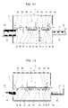
- FIG. 11 is a schematic view showing the configuration of an ink-jet printer.
- FIG. 12 is a schematic view showing another configuration of the ink-jet printer.
- an ink-jet printer will be illustrated as an application of the paper ejecting device of the present invention.
- the paper ejecting device of the present invention is also applicable to a stencil duplicator, a screen printer, and so on.
- the ink-jet printer may be configured both for single-sided and double-sided printing as shown in FIG. 11 or may be configured only for single-sided printing as shown in FIG. 12 .
- the ink-jet printer will be described with reference to FIG. 11 .
- the configurations of FIG. 12 are indicated by the same reference numerals as in FIG. 11 and the explanation thereof is omitted.
- an ink-jet printer 1 is made up of a paper feed mechanism 2 , a printer body 3 , a paper transport mechanism 4 , a paper ejecting device 5 , and a paper receiving mechanism 6 .
- the paper feed mechanism 2 includes a feed tray 22 for loading sheets 21 , a feed roller 23 and a feed pad 24 which transport the sheets 21 one by one from the feed tray 22 , and a plurality of upper and lower transport rollers 25 in pairs for supplying the transported sheets 21 to the printer body 3 .
- the printer body 3 performs printing by spraying water based ink onto a sheet surface according to an ink-jet printing system.
- a transport path is formed by a combination of a plurality of transport units 41 , gates 42 , and a pair of reversing rollers 43 .
- the gates 42 are disposed at the branch points and junctions of the transport path made up of the plurality of transport units 41 , and the transport path is switched by operating the gates 42 .
- the transport unit 41 includes a suction box 44 communicating with a suction source, a pair of a driving roller 45 and a driven roller 46 which are disposed at the front and rear of the suction box 44 , and a paper suction transport belt 47 looped over the rollers 45 and 46 at the front and rear.
- the sheets 21 are transported on the upper surface of the paper suction transport belt 47 by sucking air through a plurality of holes formed on the suction box 44 and the paper suction transport belt 47 .
- the paper receiving mechanism 6 includes a paper receiving tray 61 for receiving printed sheets 71 which are ejected from the paper ejecting device 5 .
- the paper ejecting device 5 transports the printed sheets 71 by sucking air and includes a body 51 , jumping boards 52 disposed on both sides of the body 51 , and an air blower 53 for blowing air to the paper transport surfaces of the jumping boards 52 with a fan and the like.
- the air blower 53 blows air from the center to both sides of a sheet.
- the body 51 includes a suction box 81 communicating with the suction source, drive rollers 82 and driven rollers 83 which are disposed in pairs at the front and rear of the suction box 81 , a drive shaft 84 , and paper suction transport belts 85 looped over the rollers 82 and 83 at the front and rear.
- Two pairs of the rollers 82 and 83 and the paper suction transport belts 85 are disposed in parallel with each other and the single drive shaft 84 simultaneously drives the paper suction transport belts 85 on the right and left.
- the printed sheets 71 are transported on the upper surfaces of the paper suction transport belts 85 by sucking air through a plurality of holes formed on the suction box 81 and the paper suction transport belts 85 .
- the jumping boards 52 each include a suction box 91 which acts as a sucker and communicates with the suction source, a pair of a drive roller 92 and a driven roller 93 which are disposed at the front and rear of the suction box 91 , a drive shaft 94 , a paper suction transport belt 95 looped over the rollers 92 and 93 at the front and rear, a tilted guide plate 96 and an expanded guide plate 97 which compose a paper transport surface, and a universal joint 98 provided at a point on the drive shaft 94 .
- the expanded guide plate 97 rotatively holds the drive shaft 94 and the drive shaft 94 slidably fits into a hole 84 a of the drive shaft 84 of the body 51 in an axial direction.
- the drive shaft 94 of the jumping board 52 and the drive shaft 84 of the body 51 are engaged with a key 94 a around the axis, and the key 94 a slides with the drive shaft 94 of the jumping board 52 in the axial direction while being engaged with a key groove 84 b formed in the hole 84 a of the drive shaft 84 of the body 51 .
- the jumping board 52 can slide in the axial direction of the drive shaft 84 of the body 51 , that is, the jumping board 52 can move to any position in a direction orthogonal to a paper transport direction.
- the tilted guide plate 96 is connected via a hinge 99 so as to be vertically tilted at any angle relative to the expanded guide plate 97 .
- the tilting axis of the hinge 99 is disposed in parallel with the paper transport direction. However, the tilting axis of the hinge 99 may be disposed not in parallel with the paper transport direction and the configuration will be described later.
- the drive shaft 94 rotates in synchronization with the drive shaft 84 of the body 51
- the paper suction transport belt 95 is driven in synchronization with the paper suction transport belts 85 of the body 51
- the printed sheet 71 is transported on the upper surface of the paper suction transport belt 95 , which composes a part of the paper transport surface, by sucking air through a plurality of holes formed on the suction box 91 and the paper suction transport belt 95 .
- the air suction forces of the suction boxes 81 and 91 can be adjusted, for example, by controlling the number of revolutions of a fan in the suction source, the transport speeds of the paper suction transport belts 85 and 95 , that is, the transport speed of a sheet can be adjusted by controlling the number of revolutions of the drive shafts 84 and 94 , the angle of the jumping board 52 can be adjusted by tilting the hinge 99 , and the pitch of the jumping board 52 can be adjusted by sliding the drive shafts 84 and 94 .
- the paper ejecting device 5 of the present embodiment includes a curling corrector which is the suction box 91 for sucking the printed sheet 71 and a curling corrector which is the air blower 53 for blowing air to the paper transport surfaces of the jumping boards 52 .
- Only one of the curling correctors may be provided or a transport belt of an electrostatic attraction type may be used instead of the suction box 91 and the paper suction transport belt 95 .
- the paper feed mechanism 2 feeds the sheets 21 one by one to the printer body 3 .
- the transport unit 41 transports the sheet 21 by suction through the paper suction transport belt 47 , and the printer body 3 performs printing on one surface of the sheet 21 .
- the printed sheet 71 is transferred from the transport unit 41 to the paper ejecting device 5 , and the paper ejecting device 5 transports the printed sheet 71 by suction through the paper suction transport belts 85 and 95 and ejects the printed sheet 71 to the paper receiving tray 61 .
- the printed sheet 71 may be rolled from a surface printed with liquid ink to the opposite surface.
- the printed sheet 71 may be curled downward into a reversed U-shape from the front side, which is directed upward, to the back side.
- the printed sheet 71 is sucked on the upper surfaces of the paper suction transport belts 85 of the body 51 and the upper surfaces of the paper suction transport belts 95 of the jumping boards 52 in the paper ejecting device 5 .
- the surfaces of the printed sheet 71 are shaped along the paper transport surface on the upper surface of the suction box 81 of the body 51 and the paper transport surfaces on the upper surfaces of the tilted guide plates 96 and the expanded guide plates 97 of the jumping boards 52 , so that curling of the printed sheet 71 can be corrected.
- the paper transport surface of the tilted guide plate 96 of the jumping board 52 is inclined at a predetermined angle relative to the paper transport surface of the body 51 .
- curling of the printed sheet 71 is inverted and corrected and the printed sheet 71 is curved so as to raise the sheet ends provided in parallel with an axis disposed along a jumping direction, so that the shape of the printed and ejected sheet 71 can be adjusted to a predetermined shape.
- the suction box 91 of the jumping board 52 composes the curling corrector. Curling can be more properly corrected by adjusting the air suction forces of the suction boxes 81 and 91 , the transport speeds of the paper suction transport belts 85 and 95 , the angle of the jumping board 52 , and the pitch of the jumping board 52 according to the kind of paper.
- the paper suction transport belts 95 moving with a sheet realize a friction reducer for reducing friction on the paper transport surfaces of the jumping boards 52 .
- a force applied to the printed sheet 71 by air suction acts as a force which presses the surface of the printed sheet 71 to the paper suction transport belts 95 composing a part of the paper transport surface but does not press the surface of the printed sheet 71 to the other paper transport surface of the tilted guide plate 96 .
- friction between the surface of the printed sheet 71 and the paper transport surface is small and does not become a transport resistance, so that wrinkles do not occur even when the printed sheet 71 is, for example, a thin sheet having low stiffness.
- the friction reducer may be realized by other configurations, which will be described later.
- the paper feed mechanism 2 feeds the sheets one by one to the printer body 3 .
- the transport unit 41 transports the sheet 21 by suction through the paper suction transport belt 47 , and the printer body 3 performs printing on one surface of the sheet 21 .
- the printed sheet 71 is inverted in the paper transport mechanism 4 and then is returned to the feed port of the printer body 3 .
- the gate 42 disposed between the paper ejecting device 5 and the transport unit 41 immediately below the printer body 3 is operated to temporarily feed the printed sheet 71 to the pair of reversing rollers 43 , and then the reversing rollers 43 are reversely operated to feed the printed sheet 71 to the transport unit 41 composing a return path.
- the gate 42 disposed between the transport rollers 25 and the transport unit 41 immediately below the printer body 3 is operated to feed back the printed sheet 71 to the feed port of the printer body 3 .
- the transport unit 41 transports the printed sheet 71 by suction through the paper suction transport belt 47 , and the printer body 3 performs printing on the back side of the printed sheet 71 .
- the printed sheet 71 is transferred from the transport unit 41 to the paper ejecting device 5 , and the paper ejecting device 5 transports the printed sheet 71 by suction through the paper suction transport belts 85 and 95 and ejects the printed sheet 71 to the paper receiving tray 61 .
- the printed sheet may be rolled from a surface having a large print rate to the other surface having a small print rate.
- the printed sheet 71 may be curled downward into a reversed U-shape from the front side, which is directed upward, to the back side of the sheet when the front side has a higher surface print rate.
- the printed sheet 71 may be curled upward into a U-shape from the back side, which is directed downward, to the front side of the sheet when the back side has a higher print rate.
- the printed sheet 71 is sucked on the upper surfaces of the paper suction transport belts 85 of the body 51 and the upper surfaces of the paper suction transport belts 95 of the jumping boards 52 in the paper ejecting device 5 .
- the surfaces of the printed sheet 71 are shaped along the paper transport surface on the upper surface of the suction box 81 of the body 51 and the paper transport surfaces on the upper surfaces of the tilted guide plates 96 and the expanded guide plates 97 of the jumping boards 52 , so that curling of the printed sheet 71 can be corrected.
- Air from the air blower 53 is locally blown from the center to both ends of the printed sheet 71 . Thus it is possible to prevent air from blowing to unnecessary points and efficiently correct curling.
- curling of the printed sheet 71 can be positively corrected even when the printed sheet 71 is curled upward into a U-shape as well as when the printed sheet 71 is curled downward into a reversed U-shape.
- the curling corrector of the present invention is effective particularly when the printed sheet 71 is curled into a reversed U-shape.
- a controller (not shown) determines print rates on both surfaces of the sheet 21 before printing and the sheet 21 is printed after image data is exchanged between both surfaces of the sheet 21 such that the surface having a higher print rate is directed upward when the sheet 21 is ejected to the paper ejecting device 5 .
- the curling corrector obtained by air suction of the suction box 91 and the curling corrector obtained by air blowing from the air blower 53 are combined.
- the printed sheet 71 can be corrected only by blowing air from the air blower 53 without air suction of the suction box 91 .
- the paper transport surfaces of the tilted guide plates 96 of the jumping boards 52 are each inclined at a predetermined angle relative to the paper transport surface of the body 51 .
- curling of the printed sheet 71 is inverted and corrected, and the printed sheet 71 is curved so as to raise the sheet ends provided in parallel with the axis disposed along the jumping direction, so that the shape of the printed and ejected sheet 71 can be adjusted to the predetermined shape.
- the tilted guide plate 96 is connected via the hinge 99 so as to be vertically tilted relative to the expanded guide plate 97 .
- the tilting axis of the hinge 99 is disposed in parallel with the paper transport direction.
- the tilting axis of the tilted guide plate 96 and the expanded guide plate 97 can be disposed so as to form a predetermined angle relative to the paper transport direction and the tilting axis of the hinge 99 is disposed not in parallel with the paper transport direction.
- the tilted guide plates 96 and the expanded guide plates 97 of the jumping boards 52 can slide in the width direction of the sheet as in the foregoing embodiment.
- suction holes 96 a and 97 a are formed on the tilted guide plates 96 and the expanded guide plates 97 , the suction holes 96 a of the tilted guide plates 96 are caused to communicate with the suction boxes 91 through flexible tubes 96 b such as a pleated flexible tube, and air is sucked by the suction boxes 91 through the suction holes 96 a and 97 a , so that the curling corrector is realized.
- the paper suction transport belt 95 composing a part of the paper transport surface of the jumping board 52 moves with the sheet, thereby realizing the friction reducer for reducing friction on the paper transport surface of the jumping board 52 .
- the friction reducer may be realized by using, for example, a low-friction material such as resin for members such as the tilted guide plate 96 and the expanded guide plate 97 which compose the paper transport surface. Further, the friction reducer may be realized by coating the surfaces of members such as the tilted guide plate 96 and the expanded guide plate 97 with a publicly known low-friction material such as polytetrafluoroethylene (PTFE).
- a low-friction material such as resin for members such as the tilted guide plate 96 and the expanded guide plate 97 which compose the paper transport surface.
- PTFE polytetrafluoroethylene
- the friction reducer may be realized by forming a plurality of protrusions 100 or concave and convex portions (not shown) on the paper transport surface of the paper ejecting device 5 to reduce a contact area between the paper transport surface and the sheet.
- the protrusions 100 or the concave and convex portions (not shown) may be formed with an expanded area or may be formed in rows along the transport direction of the sheet.
- the friction reducer may be realized by forming a plurality of ribs 101 on the paper transport surface of the paper ejecting device 5 along the transport direction of the sheet to reduce a contact area between the paper transport surface and the sheet.
- the friction reducer may be realized by providing a plurality of rollers 102 on the paper transport surface of the paper ejecting device 5 to have rolling friction.
Landscapes
- Engineering & Computer Science (AREA)
- Mechanical Engineering (AREA)
- Separation, Sorting, Adjustment, Or Bending Of Sheets To Be Conveyed (AREA)
- Delivering By Means Of Belts And Rollers (AREA)
- Feeding Of Articles By Means Other Than Belts Or Rollers (AREA)
Abstract
Description
Claims (10)
Applications Claiming Priority (2)
| Application Number | Priority Date | Filing Date | Title |
|---|---|---|---|
| JP2008-043676 | 2008-02-26 | ||
| JP2008043676A JP4954119B2 (en) | 2008-02-26 | 2008-02-26 | Paper discharge device |
Publications (2)
| Publication Number | Publication Date |
|---|---|
| US20090212484A1 US20090212484A1 (en) | 2009-08-27 |
| US7686295B2 true US7686295B2 (en) | 2010-03-30 |
Family
ID=40997530
Family Applications (1)
| Application Number | Title | Priority Date | Filing Date |
|---|---|---|---|
| US12/357,475 Expired - Fee Related US7686295B2 (en) | 2008-02-26 | 2009-01-22 | Paper ejecting device |
Country Status (2)
| Country | Link |
|---|---|
| US (1) | US7686295B2 (en) |
| JP (1) | JP4954119B2 (en) |
Cited By (4)
| Publication number | Priority date | Publication date | Assignee | Title |
|---|---|---|---|---|
| US20090116883A1 (en) * | 2007-11-07 | 2009-05-07 | Fuji Xerox Co., Ltd. | Discharge device and image forming apparatus |
| US20140240382A1 (en) * | 2013-02-22 | 2014-08-28 | Seiko Epson Corporation | Printing device and method for controlling printing device |
| US20150093215A1 (en) * | 2013-03-15 | 2015-04-02 | R. R. Donnelley & Sons Company | Imaging apparatus and methods for bindery systems |
| US20160082750A1 (en) * | 2013-07-29 | 2016-03-24 | Hewlett-Packard Development Company, L.P. | Media output guide assembly |
Families Citing this family (11)
| Publication number | Priority date | Publication date | Assignee | Title |
|---|---|---|---|---|
| JP2009255564A (en) * | 2008-03-28 | 2009-11-05 | Fujifilm Corp | Inkjet recording method |
| JP5135089B2 (en) * | 2008-07-04 | 2013-01-30 | 京セラドキュメントソリューションズ株式会社 | Inkjet recording device |
| JP2011093671A (en) * | 2009-10-30 | 2011-05-12 | Kyocera Mita Corp | Image forming device |
| US8862047B2 (en) | 2010-03-25 | 2014-10-14 | Kyocera Document Solutions Inc. | Sheet curl correction apparatus and image forming apparatus |
| JP5303526B2 (en) * | 2010-08-31 | 2013-10-02 | 京セラドキュメントソリューションズ株式会社 | Image forming apparatus |
| JP5577893B2 (en) * | 2010-06-30 | 2014-08-27 | ブラザー工業株式会社 | Image recording device |
| JP2014181130A (en) * | 2013-03-21 | 2014-09-29 | Fujifilm Corp | Image forming apparatus |
| JP6362417B2 (en) * | 2014-05-23 | 2018-07-25 | キヤノン株式会社 | Image forming apparatus |
| JP6669395B2 (en) * | 2016-03-30 | 2020-03-18 | キヤノン株式会社 | Sheet conveying device and image forming device |
| ES2681961B1 (en) * | 2017-03-17 | 2019-06-27 | Simon Corrugated Machinery S L | Device and procedure for the transport of flexible sheets |
| WO2021034306A1 (en) * | 2019-08-16 | 2021-02-25 | Newspaper Solutions, LLC | Inserter hopper device |
Citations (6)
| Publication number | Priority date | Publication date | Assignee | Title |
|---|---|---|---|---|
| US2381430A (en) * | 1943-07-02 | 1945-08-07 | Christensen Machine Co | Sheet delivery mechanism |
| US5975521A (en) * | 1997-04-18 | 1999-11-02 | Omron Corporation | Sheet discharging apparatus having mechanically driven wings |
| US6497522B2 (en) * | 2000-04-17 | 2002-12-24 | Hewlett-Packard Company | Edge lift reduction for belt type transports |
| US6581928B1 (en) * | 1999-10-20 | 2003-06-24 | Heidelberger Druckmaschinen Ag | Sheet guide device for sheet-processing machine |
| US6701841B2 (en) * | 2000-02-22 | 2004-03-09 | Riso Kagaku Corporation | Sheet discharge unit |
| US7300051B1 (en) * | 2003-10-24 | 2007-11-27 | Stolle Machinery Company, Llc | Rippler for a paper deliverer |
Family Cites Families (7)
| Publication number | Priority date | Publication date | Assignee | Title |
|---|---|---|---|---|
| JPH0632487A (en) * | 1992-07-13 | 1994-02-08 | Matsushita Electric Ind Co Ltd | Paper sheet conveying device for copying machine |
| JP2001010195A (en) * | 1999-06-29 | 2001-01-16 | Tohoku Ricoh Co Ltd | Printer |
| JP2001018512A (en) * | 1999-07-12 | 2001-01-23 | Riso Kagaku Corp | Paper transport device |
| JP2001316011A (en) * | 2000-05-11 | 2001-11-13 | Tohoku Ricoh Co Ltd | Paper suction conveying device and printing device on stencil printing plate |
| JP2003026353A (en) * | 2001-07-12 | 2003-01-29 | Fuji Xerox Co Ltd | Image forming device and sheet guide therefor |
| JP2007226015A (en) * | 2006-02-24 | 2007-09-06 | Noritsu Koki Co Ltd | Photo printing device |
| JP2007246181A (en) * | 2006-03-13 | 2007-09-27 | Tohoku Ricoh Co Ltd | Printing apparatus |
-
2008
- 2008-02-26 JP JP2008043676A patent/JP4954119B2/en not_active Expired - Fee Related
-
2009
- 2009-01-22 US US12/357,475 patent/US7686295B2/en not_active Expired - Fee Related
Patent Citations (6)
| Publication number | Priority date | Publication date | Assignee | Title |
|---|---|---|---|---|
| US2381430A (en) * | 1943-07-02 | 1945-08-07 | Christensen Machine Co | Sheet delivery mechanism |
| US5975521A (en) * | 1997-04-18 | 1999-11-02 | Omron Corporation | Sheet discharging apparatus having mechanically driven wings |
| US6581928B1 (en) * | 1999-10-20 | 2003-06-24 | Heidelberger Druckmaschinen Ag | Sheet guide device for sheet-processing machine |
| US6701841B2 (en) * | 2000-02-22 | 2004-03-09 | Riso Kagaku Corporation | Sheet discharge unit |
| US6497522B2 (en) * | 2000-04-17 | 2002-12-24 | Hewlett-Packard Company | Edge lift reduction for belt type transports |
| US7300051B1 (en) * | 2003-10-24 | 2007-11-27 | Stolle Machinery Company, Llc | Rippler for a paper deliverer |
Cited By (9)
| Publication number | Priority date | Publication date | Assignee | Title |
|---|---|---|---|---|
| US20090116883A1 (en) * | 2007-11-07 | 2009-05-07 | Fuji Xerox Co., Ltd. | Discharge device and image forming apparatus |
| US8235383B2 (en) * | 2007-11-07 | 2012-08-07 | Fuji Xerox Co., Ltd. | Discharge device and image forming apparatus |
| US20140240382A1 (en) * | 2013-02-22 | 2014-08-28 | Seiko Epson Corporation | Printing device and method for controlling printing device |
| US8915574B2 (en) * | 2013-02-22 | 2014-12-23 | Seiko Epson Corporation | Printing device and method for controlling printing device |
| US20150093215A1 (en) * | 2013-03-15 | 2015-04-02 | R. R. Donnelley & Sons Company | Imaging apparatus and methods for bindery systems |
| US9457974B2 (en) * | 2013-03-15 | 2016-10-04 | R.R. Donnelley & Sons Company | Imaging apparatus and methods for bindery systems |
| US9944477B2 (en) | 2013-03-15 | 2018-04-17 | Lsc Communications Us, Llc | Imaging apparatus and methods for bindery systems |
| US20160082750A1 (en) * | 2013-07-29 | 2016-03-24 | Hewlett-Packard Development Company, L.P. | Media output guide assembly |
| US9656484B2 (en) * | 2013-07-29 | 2017-05-23 | Hewlett-Packard Development Company, L.P. | Media output guide assembly |
Also Published As
| Publication number | Publication date |
|---|---|
| JP4954119B2 (en) | 2012-06-13 |
| JP2009202952A (en) | 2009-09-10 |
| US20090212484A1 (en) | 2009-08-27 |
Similar Documents
| Publication | Publication Date | Title |
|---|---|---|
| US7686295B2 (en) | Paper ejecting device | |
| US8210527B2 (en) | Paper ejecting device with swinging protruding members | |
| US9290344B2 (en) | Ink-jet printer | |
| US8491072B2 (en) | Inkjet printing apparatus | |
| US10549554B2 (en) | Printing apparatus and platen | |
| US9409732B2 (en) | Sheet-like object transporting device and ink-jet printer | |
| JP5956824B2 (en) | Image forming apparatus | |
| US8167302B2 (en) | Paper inverting device | |
| US8052143B2 (en) | Paper inverting device | |
| JP2008273663A (en) | Paper receiving device | |
| US9643806B2 (en) | Paper transfer device | |
| JP5065073B2 (en) | Paper discharge device | |
| US8052142B2 (en) | Paper transport apparatus with inverting turn guide having range of curvature radius | |
| US10011131B2 (en) | Printing apparatus | |
| CN110342315B (en) | Sheet discharge tray and image forming apparatus | |
| JP2019107808A (en) | Printer and printing control method | |
| JP5620754B2 (en) | Inkjet printing device | |
| JP2000246982A (en) | Ink jet recording apparatus and paper-transferring apparatus | |
| JP3384385B2 (en) | Recording medium transport device for printer and printer equipped with the same | |
| JP6213433B2 (en) | Inkjet recording device | |
| JP7521985B2 (en) | Conveyor | |
| JP2007161371A (en) | Paper feeding device | |
| JP2010082814A (en) | Image forming apparatus | |
| JP2019043689A (en) | Printing device | |
| JP2007126277A (en) | Paper feeder |
Legal Events
| Date | Code | Title | Description |
|---|---|---|---|
| AS | Assignment |
Owner name: DUPLO SEIKO CORPORATION, JAPAN Free format text: ASSIGNMENT OF ASSIGNORS INTEREST;ASSIGNORS:KAWAGUCHI, AKIRA;TAKAHASHI, KATSUNORI;TANIMOTO, NOBUKI;REEL/FRAME:022193/0067 Effective date: 20090121 Owner name: DUPLO SEIKO CORPORATION,JAPAN Free format text: ASSIGNMENT OF ASSIGNORS INTEREST;ASSIGNORS:KAWAGUCHI, AKIRA;TAKAHASHI, KATSUNORI;TANIMOTO, NOBUKI;REEL/FRAME:022193/0067 Effective date: 20090121 |
|
| STCF | Information on status: patent grant |
Free format text: PATENTED CASE |
|
| AS | Assignment |
Owner name: DUPLO SEIKO CORPORATION,JAPAN Free format text: ASSIGNMENT OF ASSIGNORS INTEREST;ASSIGNOR:DUPLO SEIKO CORPORATION;REEL/FRAME:024505/0896 Effective date: 20100601 Owner name: SEIKO EPSON CORPORATION,JAPAN Free format text: ASSIGNMENT OF ASSIGNORS INTEREST;ASSIGNOR:DUPLO SEIKO CORPORATION;REEL/FRAME:024505/0896 Effective date: 20100601 Owner name: DUPLO SEIKO CORPORATION, JAPAN Free format text: ASSIGNMENT OF ASSIGNORS INTEREST;ASSIGNOR:DUPLO SEIKO CORPORATION;REEL/FRAME:024505/0896 Effective date: 20100601 Owner name: SEIKO EPSON CORPORATION, JAPAN Free format text: ASSIGNMENT OF ASSIGNORS INTEREST;ASSIGNOR:DUPLO SEIKO CORPORATION;REEL/FRAME:024505/0896 Effective date: 20100601 |
|
| FPAY | Fee payment |
Year of fee payment: 4 |
|
| MAFP | Maintenance fee payment |
Free format text: PAYMENT OF MAINTENANCE FEE, 8TH YEAR, LARGE ENTITY (ORIGINAL EVENT CODE: M1552) Year of fee payment: 8 |
|
| FEPP | Fee payment procedure |
Free format text: MAINTENANCE FEE REMINDER MAILED (ORIGINAL EVENT CODE: REM.); ENTITY STATUS OF PATENT OWNER: LARGE ENTITY |
|
| LAPS | Lapse for failure to pay maintenance fees |
Free format text: PATENT EXPIRED FOR FAILURE TO PAY MAINTENANCE FEES (ORIGINAL EVENT CODE: EXP.); ENTITY STATUS OF PATENT OWNER: LARGE ENTITY |
|
| STCH | Information on status: patent discontinuation |
Free format text: PATENT EXPIRED DUE TO NONPAYMENT OF MAINTENANCE FEES UNDER 37 CFR 1.362 |
|
| FP | Lapsed due to failure to pay maintenance fee |
Effective date: 20220330 |