US7684530B2 - Circuit arrangement and method for synchronised transmission of audio data streams in a bus system - Google Patents
Circuit arrangement and method for synchronised transmission of audio data streams in a bus system Download PDFInfo
- Publication number
- US7684530B2 US7684530B2 US10/467,091 US46709103A US7684530B2 US 7684530 B2 US7684530 B2 US 7684530B2 US 46709103 A US46709103 A US 46709103A US 7684530 B2 US7684530 B2 US 7684530B2
- Authority
- US
- United States
- Prior art keywords
- data
- frequency
- recited
- unit
- clock
- Prior art date
- Legal status (The legal status is an assumption and is not a legal conclusion. Google has not performed a legal analysis and makes no representation as to the accuracy of the status listed.)
- Expired - Fee Related, expires
Links
Images


Classifications
-
- H—ELECTRICITY
- H04—ELECTRIC COMMUNICATION TECHNIQUE
- H04L—TRANSMISSION OF DIGITAL INFORMATION, e.g. TELEGRAPHIC COMMUNICATION
- H04L12/00—Data switching networks
- H04L12/28—Data switching networks characterised by path configuration, e.g. LAN [Local Area Networks] or WAN [Wide Area Networks]
- H04L12/42—Loop networks
- H04L12/427—Loop networks with decentralised control
- H04L12/433—Loop networks with decentralised control with asynchronous transmission, e.g. token ring, register insertion
Definitions
- the present invention relates to a circuit system and to a method for synchronized transmission of audio data streams in a bus system based on, for example, the IEEE 1394 Standard.
- Synchronization between data sources and data sinks in data buses which are based on asynchronous data transmission is conventionally achieved by the “time stamp” method.
- time stamp methods have been developed for the IEEE 1394 Standard which likewise are based on the time stamp principle; the approach selected thus far, however, is based on the fact that the data source communicates the data sample rate to the data sink via a control channel before the transmission of the audio data begins.
- Data packets having multiple audio data samples are subsequently transmitted via an isochronous data channel, each data packet being provided with a “time stamp” which represents the presentation time of the first audio data sample.
- the sample data frequency must be recovered using a phase locked loop (PLL) circuit and using information about the number of data samples per data packet.
- PLL phase locked loop
- An object of an example embodiment of the present invention is to provide a circuit system and a method of the aforementioned type whereby the sample data frequency of the data source may be recovered in the data sink without a PLL circuit system.
- a further object of an example embodiment of the present invention is to enable the transmission of multiple audio channels via the bus system in parallel and using different data sample rates.
- a further object of an example embodiment of the present invention is to enable the integration of externally synchronizable data sources and/or non-externally synchronizable data sources into the circuit system and into the method.
- a synchronization mechanism for transmitting audio data in a bus system is provided for the circuit system and for the method.
- a PLL circuit is not required for regenerating the (sample) data frequency in the data source.
- most of the jitters present in the bus system do not have an effect on the synchronization mechanism.
- the synchronization mechanism provided by an example embodiment of the present invention cannot be used for transmitting audio data based on the IEEE 1394 Standard, but instead is used for transmitting other types of data and/or for other applications requiring a fixed coupling between the data source and the data sink.
- the IEEE 1394 Standard may still be used to achieve a rapid and uncomplicated data exchange, for example, in the entertainment field, between up to 63 devices currently at a maximum of 400 Mbit/second (up to 3,200 Mbit/second are planned).
- packets are first transmitted which contain the address of the data source and of the data sink.
- the data sink receives the packet, it sends back an acknowledgment packet to the data source, and the transmission of the actual data packet is able to begin.
- an isochronous channel in a specific band width is required between the data source and the data sink.
- An unambiguous channel identification number (channel ID) is assigned to this channel; the data source then transmits only the channel identification number, followed by the data, and the data sink receives only the data having this channel identification number, a maximum of 64 isochronous channels being possible. The remainder of the bandwidth not occupied by the isochronous transfer is available for the transmission of asynchronous data packets.
- a circuit system ( 100 ) and a method for synchronized transmission of audio data streams in a bus system, for example based on the IEEE 1394 Standard, is provided.
- the sample data frequency of the data source may be recovered in the data sink without a PLL circuit system.
- the circuit system ( 100 ) includes at least one data source ( 10 ) which provides audio data packets (AD) to be transmitted, for example, asynchronously and/or isochronously, in addition to frequency data packets (FS) which are associated with the particular audio data packets (AD) to be transmitted, and which are to be transmitted, for example, asynchronously.
- AD audio data packets
- FS frequency data packets
- the data source ( 10 ) has at least one clock or timer unit ( 12 ) for updating, for example periodically, at least one synchronization cycle or time cycle in the circuit system ( 100 ).
- the data source ( 10 ) also has at least one generator unit ( 14 ) which is connected ( 124 ) to the clock or timer unit ( 12 ) and which receives at least one data frequency (Fs).
- the data frequency (Fs) may be used for reading the particular counter status of the clock or timer unit ( 12 ) according to the data frequency (Fs).
- the data frequency (Fs) may also be used for adding a predetermined, for example, constant, value to the counter status read.
- the data frequency (Fs) may also be used for entering the value into the frequency data packet (FS).
- the data frequency (Fs) may also be used for sending the frequency data packet (FS) after a predetermined number of values in the frequency data packet (FS) has been reached.
- the data source ( 10 ) also includes at least one data sink ( 40 ), which is connected to the data source ( 10 ) via at least one data channel ( 30 , 32 ) and which receives the audio data packet (AD) to be transmitted, in addition to the particular associated frequency data packet (FS).
- the frequency data packet (FS) has at least one clock or timer unit ( 42 ) for updating, for example, periodically, the synchronization cycle or time cycle.
- the frequency data packet (FS) also has at least one audio data buffer unit ( 44 ) for entering the counter status of the received audio data packets (AD).
- the frequency data packet (FS) also has at least one data frequency buffer unit ( 46 ) for entering the counter status of the received frequency data packets (FS).
- the frequency data packet (FS) also has at least one comparator unit ( 48 ), which is connected ( 428 ) to the clock or timer unit ( 42 ) and is also connected ( 468 ) to the data frequency buffer unit ( 46 ).
- the frequency data packet (FS) is used for comparing the counter status of the clock or timer unit ( 42 ) to the counter status of the data frequency buffer unit ( 46 ).
- the frequency data packet (FS) is also used for sending at least one data frequency pulse (fs).
- the frequency data packet (FS) also has at least one output unit ( 50 ), which is connected ( 445 ) to the audio data buffer unit ( 44 ) and is also connected ( 485 ) to the comparator unit ( 48 ), for outputting the audio data pulse (ad) read from the audio data buffer unit ( 44 ) together with the data frequency pulse (fs) which is transmitted from the comparator unit ( 48 ) and which is associated with the audio data pulse (ad).
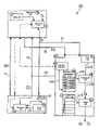
- FIG. 1 is a schematic diagram of a circuit system according to an example embodiment of the present invention.
- FIG. 2 is a schematic diagram plotted against time of an example asynchronous transmission of three frequency data packets using the circuit system according to FIG. 1 .
- Circuit system 100 includes a data source 10 as the transmitting unit and a data sink 40 as the receiving unit, as well as an additional data source 20 to be explained in greater detail below.
- Data source 10 , additional data source 20 , and data sink 40 each function as bus nodes in the bus system in which circuit system 100 is situated.
- a clock or timer unit 12 , 22 , or 42 is provided which in the case of a bus system based on the IEEE 1394 Standard is a “1394 timer,” i.e., a register containing the uniform time base for the entire data bus.
- the clock or timer unit 12 , 22 , or 42 is periodically updated with a frequency of approximately 8 Kilohertz, i.e., is set back to the value of the timing register contained in clock or timer unit 12 .
- this value is not set back even when the bus system is reset; this value is not set back to zero unless the timing register overflows.
- the timing register contained in clock or timer unit 12 forms the basis for the synchronization.
- Sample frequency (data frequency) Fs or Fs+ is present at one of the inputs of generator unit 14 or 24 , respectively.
- generator unit 14 or 24 reads the counter status from the timing register of clock or timer unit 12 or 22 , adds a constant value, which is the transmission delay, thereto, and enters the value into an asynchronous frequency data packet FS or FS+.
- a field which contains information about the contents of the data packet and about the synchronization method used in that instance is to be added in the header of the particular data packet.
- this asynchronous frequency data packet is transmitted to data sink 40 via data channel 32 or 38 , respectively, either “unicast,” “broadcast to the group,” or “broadcast to all.”
- Data sink 40 enters the received values of transmitted frequency data packet FS into a data frequency buffer unit 46 .
- a comparator unit 48 which likewise is associated with data sink 40 , the counter states of clock or timer unit 42 arriving via connection 428 are now compared to the first value in data frequency buffer unit 46 arriving via connection 468 .
- a data frequency pulse fs is output by comparator unit 48 via connecting line 485 , which in principle is again the sample frequency or data frequency Fs generated in data source 10 , or the sample frequency or data frequency Fs+generated in additional data source 20 .
- audio data packets AD or AD+ containing the associated audio data are transmitted via an asynchronous or isochronous data channel 30 or 34 , respectively.
- These audio samples are entered in data sink 40 into an audio data buffer unit 44 .
- Output unit 50 which likewise is associated with data sink 40 and which is designed in the form of an I2S output unit, for example, reads at every pulse from comparator unit 48 the instantaneous value from audio data buffer unit 44 via connection 445 , and sends both values in the form of the audio data pulse and data frequency pulse fs, for example in the I2S format.
- Data flow controller 60 By using a data flow controller 60 , which likewise is associated with data sink 40 , it is possible to avoid idling operation or an overflow of audio data buffer unit 44 and/or data frequency buffer unit 46 in data sink 40 .
- Data flow controller 60 includes a feedback loop to data source 10 (see the dashed line in FIG. 1 ).
- data flow controller 60 may be used internally, i.e., in data sink 40 , to dampen the level of the audio signal in a timely manner during idling operation, in particular in audio data buffer unit 44 , thus avoiding an interfering clicking sound in the loudspeaker.
- a management unit designated in circuit system 100 in the form of an “audio master” manages a list of all sample frequencies or data frequencies transmitted, i.e., used in the bus system (for the embodiment according to FIG. 1 , sample frequencies or data frequencies Fs or Fs+, respectively). If an additional data source 20 is now connected to the bus system, it must first be determined whether or not this additional data source 20 is externally synchronizable.
- this additional data source 20 is externally synchronizable, it is further determined whether, in the bus system, data packets having the corresponding sample frequency or data frequency Fs+ are already being transmitted to additional data source 20 . These mechanisms operate between the management unit and data source 10 or additional data source 20 .
- additional data source 20 transmits audio data packets AD+via asynchronous or isochronous channel 34 .
- additional data source 20 is not externally synchronizable, and the sample frequency or data frequency is not yet being transmitted.
- additional data source 20 generates the frequency data packets having the sample frequency or data frequency, using associated generator unit 24 . Further, additional data source 20 also generates audio data packets containing audio samples.
- additional data source 20 is not externally synchronizable, and sample frequency or data frequency Fs+ are already being transmitted. In this case, the management unit must determine whether all other data sources having this sample frequency or data frequency are externally synchronizable. When this is established, the management unit transmits to additional data source 20 the assignment to generate data packets containing the sample frequency or data frequency, and the second case previously described sets in. On the other hand, if all other data sources having this sample frequency or data frequency are not externally synchronizable, an additional sample frequency or data frequency is provided, and the second case previously described likewise sets in.
Landscapes
- Engineering & Computer Science (AREA)
- Computer Networks & Wireless Communication (AREA)
- Signal Processing (AREA)
- Synchronisation In Digital Transmission Systems (AREA)
- Small-Scale Networks (AREA)
Abstract
Description
In a second case,
Lastly, in a third case
Claims (42)
Applications Claiming Priority (4)
| Application Number | Priority Date | Filing Date | Title |
|---|---|---|---|
| DE10104876.9 | 2001-02-03 | ||
| DE10104876A DE10104876A1 (en) | 2001-02-03 | 2001-02-03 | Circuit arrangement and method for the synchronized transmission of audio data streams in a bus system |
| DE10104876 | 2001-02-03 | ||
| PCT/DE2002/000184 WO2003024008A2 (en) | 2001-02-03 | 2002-01-22 | Circuit arrangement and method for synchronised transmission of audio data streams in a bus system |
Publications (2)
| Publication Number | Publication Date |
|---|---|
| US20040088595A1 US20040088595A1 (en) | 2004-05-06 |
| US7684530B2 true US7684530B2 (en) | 2010-03-23 |
Family
ID=7672732
Family Applications (1)
| Application Number | Title | Priority Date | Filing Date |
|---|---|---|---|
| US10/467,091 Expired - Fee Related US7684530B2 (en) | 2001-02-03 | 2002-01-22 | Circuit arrangement and method for synchronised transmission of audio data streams in a bus system |
Country Status (5)
| Country | Link |
|---|---|
| US (1) | US7684530B2 (en) |
| EP (1) | EP1374460B1 (en) |
| JP (1) | JP4051339B2 (en) |
| DE (2) | DE10104876A1 (en) |
| WO (1) | WO2003024008A2 (en) |
Families Citing this family (2)
| Publication number | Priority date | Publication date | Assignee | Title |
|---|---|---|---|---|
| DE102019100507A1 (en) * | 2019-01-10 | 2020-07-16 | Northrop Grumman Litef Gmbh | Method for reading out data from inertial sensors |
| CN111125423A (en) * | 2019-11-29 | 2020-05-08 | 维沃移动通信有限公司 | A denoising method and mobile terminal |
Citations (2)
| Publication number | Priority date | Publication date | Assignee | Title |
|---|---|---|---|---|
| WO1999059047A2 (en) * | 1998-05-11 | 1999-11-18 | Digital Harmony Technologies, L.L.C. | Method and apparatus for low jitter clock recovery |
| US6404770B1 (en) * | 1997-12-02 | 2002-06-11 | Yamaha Corporation | Data communication interface with adjustable-size buffer |
Family Cites Families (4)
| Publication number | Priority date | Publication date | Assignee | Title |
|---|---|---|---|---|
| WO1995022233A1 (en) * | 1994-02-11 | 1995-08-17 | Newbridge Networks Corporation | Method of dynamically compensating for variable transmission delays in packet networks |
| JP3203978B2 (en) * | 1994-07-25 | 2001-09-04 | ソニー株式会社 | Data transmitting / receiving device, data receiving device, and data transmitting device |
| JPH10190705A (en) * | 1996-10-22 | 1998-07-21 | Sony Corp | Transmission apparatus and method, and reception apparatus and method |
| JP4577816B2 (en) * | 2001-06-29 | 2010-11-10 | トムソン ライセンシング | Multimedia jitter removal in asynchronous digital home networks |
-
2001
- 2001-02-03 DE DE10104876A patent/DE10104876A1/en not_active Withdrawn
-
2002
- 2002-01-22 EP EP02785040A patent/EP1374460B1/en not_active Expired - Lifetime
- 2002-01-22 JP JP2003527931A patent/JP4051339B2/en not_active Expired - Fee Related
- 2002-01-22 US US10/467,091 patent/US7684530B2/en not_active Expired - Fee Related
- 2002-01-22 DE DE50211251T patent/DE50211251D1/en not_active Expired - Lifetime
- 2002-01-22 WO PCT/DE2002/000184 patent/WO2003024008A2/en not_active Ceased
Patent Citations (2)
| Publication number | Priority date | Publication date | Assignee | Title |
|---|---|---|---|---|
| US6404770B1 (en) * | 1997-12-02 | 2002-06-11 | Yamaha Corporation | Data communication interface with adjustable-size buffer |
| WO1999059047A2 (en) * | 1998-05-11 | 1999-11-18 | Digital Harmony Technologies, L.L.C. | Method and apparatus for low jitter clock recovery |
Also Published As
| Publication number | Publication date |
|---|---|
| EP1374460A2 (en) | 2004-01-02 |
| WO2003024008A2 (en) | 2003-03-20 |
| DE50211251D1 (en) | 2008-01-03 |
| EP1374460B1 (en) | 2007-11-21 |
| DE10104876A1 (en) | 2002-08-08 |
| JP4051339B2 (en) | 2008-02-20 |
| US20040088595A1 (en) | 2004-05-06 |
| WO2003024008A3 (en) | 2003-10-09 |
| JP2005504462A (en) | 2005-02-10 |
Similar Documents
| Publication | Publication Date | Title |
|---|---|---|
| US7885296B2 (en) | Maintaining consistency among multiple timestamp counters distributed among multiple devices | |
| EP1256197B1 (en) | Reference time distribution over a network | |
| CN101164264B (en) | Method and device for synchronising two bus systems, and arrangement consisting of two bus systems | |
| EP1525693B1 (en) | Clock synchronizing method over fault-tolerant etherent | |
| US6718476B1 (en) | Method of synchronizing each local clock to a master clock in a data bus system | |
| EP2190147B1 (en) | Audio Network system | |
| JP3698074B2 (en) | Network synchronization method, LSI, bus bridge, network device, and program | |
| US6928126B2 (en) | Reception interface unit in transmission system | |
| US20130003757A1 (en) | Syntonized communication system | |
| JP4701263B2 (en) | Method, computer program, storage medium and device for transmitting / receiving data content in communication network | |
| JPH0373636A (en) | Data synchronizing transmission system | |
| KR100208012B1 (en) | Digital audio / video data transmission device and method | |
| US6757304B1 (en) | Method and apparatus for data communication and storage wherein a IEEE1394/firewire clock is synchronized to an ATM network clock | |
| US6633578B1 (en) | Transmission interface unit in transmission system | |
| US7684530B2 (en) | Circuit arrangement and method for synchronised transmission of audio data streams in a bus system | |
| KR100673802B1 (en) | Transmission method, transmission system and transmitter | |
| JP2004128756A (en) | Time stamp correction circuit and correction method | |
| EP1518376B1 (en) | data link layer device for a serial communication bus | |
| JP2823548B2 (en) | how to access | |
| WO2008128544A1 (en) | Low cost digital real-time link system | |
| JPH02205135A (en) | Frame configuration definition method | |
| JP2000276441A (en) | Packet transfer device | |
| JP2000278353A (en) | Packet transfer device | |
| JP2000278326A (en) | Packet transfer device | |
| JPS62290234A (en) | Frame synchronizing system for loop-type communication network |
Legal Events
| Date | Code | Title | Description |
|---|---|---|---|
| AS | Assignment |
Owner name: ROBERT BOSCH GMBH, GERMANY Free format text: ASSIGNMENT OF ASSIGNORS INTEREST;ASSIGNOR:BAIERL, WOLFGANG;REEL/FRAME:014839/0150 Effective date: 20030930 Owner name: ROBERT BOSCH GMBH,GERMANY Free format text: ASSIGNMENT OF ASSIGNORS INTEREST;ASSIGNOR:BAIERL, WOLFGANG;REEL/FRAME:014839/0150 Effective date: 20030930 |
|
| REMI | Maintenance fee reminder mailed | ||
| LAPS | Lapse for failure to pay maintenance fees | ||
| STCH | Information on status: patent discontinuation |
Free format text: PATENT EXPIRED DUE TO NONPAYMENT OF MAINTENANCE FEES UNDER 37 CFR 1.362 |
|
| STCH | Information on status: patent discontinuation |
Free format text: PATENT EXPIRED DUE TO NONPAYMENT OF MAINTENANCE FEES UNDER 37 CFR 1.362 |
|
| FP | Lapsed due to failure to pay maintenance fee |
Effective date: 20140323 |