US7683548B2 - Method of producing an infrared lamp - Google Patents

Method of producing an infrared lamp Download PDF

Info

Publication number
US7683548B2
US7683548B2 US11/571,833 US57183305A US7683548B2 US 7683548 B2 US7683548 B2 US 7683548B2 US 57183305 A US57183305 A US 57183305A US 7683548 B2 US7683548 B2 US 7683548B2
Authority
US
United States
Prior art keywords
holes
coating
lamp
infrared
tube
Prior art date
Legal status (The legal status is an assumption and is not a legal conclusion. Google has not performed a legal analysis and makes no representation as to the accuracy of the status listed.)
Expired - Fee Related, expires
Application number
US11/571,833
Other versions
US20080031003A1 (en
Inventor
Lukas Kupper
Colette Knight
Current Assignee (The listed assignees may be inaccurate. Google has not performed a legal analysis and makes no representation or warranty as to the accuracy of the list.)
Koninklijke Philips NV
Original Assignee
Koninklijke Philips Electronics NV
Priority date (The priority date is an assumption and is not a legal conclusion. Google has not performed a legal analysis and makes no representation as to the accuracy of the date listed.)
Filing date
Publication date
Application filed by Koninklijke Philips Electronics NV filed Critical Koninklijke Philips Electronics NV
Assigned to KONINKLIJKE PHILIPS ELECTRONICS N V reassignment KONINKLIJKE PHILIPS ELECTRONICS N V ASSIGNMENT OF ASSIGNORS INTEREST (SEE DOCUMENT FOR DETAILS). Assignors: KNIGHT, COLETTE, KUPPER, LUKAS
Publication of US20080031003A1 publication Critical patent/US20080031003A1/en
Application granted granted Critical
Publication of US7683548B2 publication Critical patent/US7683548B2/en
Expired - Fee Related legal-status Critical Current
Adjusted expiration legal-status Critical

Links

Images

Classifications

    • HELECTRICITY
    • H01ELECTRIC ELEMENTS
    • H01KELECTRIC INCANDESCENT LAMPS
    • H01K7/00Lamps for purposes other than general lighting
    • HELECTRICITY
    • H01ELECTRIC ELEMENTS
    • H01KELECTRIC INCANDESCENT LAMPS
    • H01K1/00Details
    • H01K1/28Envelopes; Vessels
    • H01K1/32Envelopes; Vessels provided with coatings on the walls; Vessels or coatings thereon characterised by the material thereof

Definitions

  • the invention relates to a method of producing an infrared lamp for a vehicle night vision system.
  • the invention furthermore relates to an infrared lamp produced by means of this method for a vehicle night vision system and also to a headlamp for a vehicle night vision system which comprises such an infrared lamp.
  • Infrared night vision systems have already been known for a long time in the military and police sector or even for private monitoring and security purposes. In order to increase traffic safety, attempts are being made also to equip civil motor vehicles with suitable night vision systems as an option or even as standard.
  • vehicle night vision systems usually consist of a headlamp comprising an infrared radiation source by means of which infrared light is emitted into the relevant area of the traffic space in front of the vehicle, said light being reflected by objects located in the traffic space.
  • the reflected infrared radiation is detected by an infrared-sensitive camera system which is likewise located in the vehicle, for example in the upper region behind the windscreen.
  • the infrared images recorded by said camera system are displayed on a display in the vehicle so that even under poor vision conditions the driver is informed in good time about any objects located in the traffic space.
  • vehicle night vision systems are intended for use in particular in situations where the vehicle is not in a position to use full beam in case it dazzles the oncoming traffic.
  • the vehicle night vision system can then be used to cover in particular that region in the traffic space which is further away from the vehicle and thus is not reached by the low beam. In this way, firstly the risk of endangering the oncoming traffic by dazzling it is prevented and secondly the driver can be warned about any objects located in front of the vehicle on the road or directly on the road before these objects pass into the range of the low beam and the driver can see them.
  • the time for the driver to react is considerably increased and the likelihood of an accident is thus reduced.
  • infrared radiation for such a vehicle night vision system.
  • conventional halogen lamps emit infrared radiation in addition to visible light. It is therefore possible to filter out the visible light by means of appropriate infrared-transmitting filters and thus to allow through only the infrared radiation. This may be effected for example by separate filters fitted in the headlamp.
  • a suitable IR-transmitting coating directly to the tube of the lamp, which is usually also referred to as the “bulb”.
  • the coating which should be transparent in the near-IR region to around 800 nm and should filter out the entire visible region from 400 to 800 nm. Since the human eye is sensitive up to a wavelength range of at most around 820 to 830 nm, it would be desirable if a filter could be produced which has a sharp edge in this range.
  • infrared-transmitting coatings with such sharp filter edges cannot currently be produced. This means that an amount of visible light below 800 nm is still always transmitted. These light components lie in the red color region. Without additional measures, lamps comprising an IR-transmitting coating thus necessarily also transmit red light. On the other hand, however, for safety reasons it is not permissible to use lamps which produce red light in a vehicle front headlamp since these lamps could be confused with the rear lights or brake lights of the vehicles.
  • Another alternative could be to design the filter coating such that it is transparent specifically in a given second spectral region of the visible light, for example in the blue region, so that the light transmitted in this region, mixed with the residual red light passing through the filter, results in white light.
  • the design of such filters is extremely difficult and cost-intensive. Since ultimately, however, infrared lamps for use in civil motor vehicles are mass-produced articles, the production costs represent a significant factor for determining how widely used such systems will be in the future.
  • Another approach which promises success is to ensure, by virtue of appropriate filter designs, that white visible light which is sufficient for masking the emitted red light is additionally emitted. The observer then sees a white lamp and not a red lamp. However, it should be ensured here that the white light is not too bright since dazzling of the oncoming traffic is to be avoided in all cases.
  • a tube which is preferably made of quartz glass and surrounds a radiation source that emits infrared radiation and light radiation is provided with an IR-transmitting filter coating.
  • an IR-transmitting filter coating By setting specific process parameters directly in the coating process and/or by post-treating the coated tube, it is ensured that holes form in an irregular arrangement in the coating, which holes have at least in some areas a defined, that is to say predetermined, average size and a defined average surface density.
  • the infrared lamp according to the invention therefore does not have a coating with a uniform defined pattern but rather the coating has holes in an irregular or random arrangement, wherein the holes may be irregularly shaped defects, cracks, etc.
  • the radiation source may be a single radiation source, such as for example a coil in a halogen lamp, which simultaneously emits infrared radiation and light radiation. In principle, however, it may also be a radiation source consisting of a number of partial radiation sources, wherein one partial radiation source emits infrared radiation and the other partial radiation source emits light radiation. A lamp having two different coils is conceivable here for example. For cost reasons, however, it is more advantageous to use a bulb having just one radiation source which simultaneously emits infrared radiation and light radiation. Moreover, the radiation source may in principle be any type of radiation source. In particular, it need not necessarily be a coil but rather use may also be made for example of a discharge lamp in which the radiation source is an appropriate arc or the like.
  • the tube may be the glass tube which directly surrounds the radiation source. If the lamp is a lamp which has two tubes on top of one another—one inner tube and one outer tube—such as a gas discharge lamp for example, the coating is preferably (but not necessarily) located on the outer tube.
  • the average size and the average surface density are essentially selected such that the light radiation passing through the holes during operation of the lamp already has a sufficient intensity to mask an amount of visible red light which is transmitted through the IR-transmitting coating.
  • certain part-regions of the tube which are suitable for this purpose additionally remain without the infrared-transmitting coating.
  • the average size and average density of the holes in the coating are selected such that the light radiation passing through the holes during operation of the lamp, together with the light radiation passing through the coating-free part-regions of the tube, has a sufficient intensity to mask an amount of visible red light which is transmitted through the IR-transmitting coating.
  • the pinch area and/or a sealed tip of the tube for example remain free of the infrared-transmitting coating.
  • the lamp is held in a holder during the coating process, and said holder has suitable means for screening off the desired end region(s) so that these regions are not coated.
  • the coating may also be subsequently removed in a dipping bath or the like.
  • the visible light exiting through the sealed tip and/or through the pinch would not alone be sufficient to reliably mask the residual red light, particularly since this light impinges only in very precise spatial areas.
  • the holes which according to the invention are produced in a simple manner in the coating, however, it is overall possible in a cost-effective manner to produce a lamp which emits sufficient infrared light and in which the white light passing through the holes in the coating and through the coating-free regions such as the pinch regions and/or sealed tip is sufficient to mask the residual amount of red light.
  • the spatial distribution of the light is also optimal for reliable masking without further complex structures in the reflector.
  • the infrared-transmitting coating used is preferably a multilayer coating in which a number of coating layers are applied one on top of the other to the tube, wherein the coating layers in each case have a different refractive index.
  • a layer having a high refractive index and a layer having a low refractive index are applied alternately.
  • a filter coating consists of around 20 to at most around 50 layers. Suitable materials for this are, for example, Si and SiO 2 . Silicon is a highly refractive substance having a refractive index of around 3, whereas SiO 2 is a material having a low refractive index of around 1.4.
  • the interference effect ensures that individual wavelengths are amplified and other wavelengths are blocked. Moreover, radiation in the visible region is absorbed by the Si layers.
  • appropriate materials having appropriate refractive indices and by suitably selecting the layer thicknesses in the range from around 50 to around 160 nm it can be ensured that precisely the desired filter characteristic is achieved.
  • Other highly refractive materials which may be used for the layers are TA 2 O 5 , TiO 2 , ZrO 2 and ZnS.
  • possible low-refractive layers also include MgF 2 or AlF 6 . The various possibilities are known to the person skilled in the art.
  • the layers may be applied for example by means of vapor deposition.
  • the material which is to be applied as a layer to the tube is evaporated in vacuo within an evaporation chamber at a temperature of around 1000 Kelvin for example.
  • the vaporized material then precipitates on the surface to be coated.
  • sputtering This involves spraying a surface. This process also takes place in a chamber under vacuum conditions.
  • a target is required which is made of the material to be deposited. By bombarding this target with high-energy particles, usually ions, some of the particles from the target pass into a vapor phase.
  • the energy for vaporizing the target material can also be introduced into the target by means of microwave radiation. The particles in the vapor phase pass onto the surface to be coated and precipitate there.
  • vapor-deposited layers are usually less dense and have lower internal stresses than sputtered-on layers.
  • Very dense layers having a relatively high refractive index can be produced by sputtering. These layers are very stable and there is usually no diffusion or only very slight diffusion between the individual layers which have been sputtered on one after the other.
  • a first preferred method consists in that the coated tube or the coated lamp is subjected to a defined heating process until the desired holes having the defined average size and average surface density have formed in the coating.
  • the lamp with the coating is kept at a given temperature for a given period of time.
  • This method is particularly suitable for multilayer coatings which have been applied by means of a sputtering process, particularly preferably by means of a microwave sputtering process.
  • a sputtering process particularly preferably by means of a microwave sputtering process.
  • such layers are particularly suitable for making the holes in subsequent defined thermal heating processes.
  • the reason for this is that the different layers within the coating have different thermal expansion coefficients and the desired cracks and defects occur during subsequent heating on account of the high density and the stresses created during the sputtering process.
  • the number of holes and average size of the holes depends in this case both on the heating time and on the temperature.
  • the coated tube or the lamp is kept at a given minimum temperature at least until the number and average size of the holes no longer changes significantly. It has been found that a type of saturation effect occurs after a certain time at a given temperature. The stresses within the coating are then largely broken down and the number and average size of the holes no longer changes significantly.
  • the process parameters during the coating operation and in the subsequent process are advantageously selected such that, after the targeted heat treatment, no more holes are produced by other external or internal influences of the lamp, for example by the heating of the lamp during normal operation, as this would subsequently change the defined average surface density and average size of the holes that has been set.
  • Another alternative for making holes having a defined average size and average surface density is to set the vacuum, i.e. the low pressure, when the coating is applied by sputtering or vapor-deposition. It has been found in further experiments that defects can likewise deliberately be made in the coating by increasing the pressure compared to the pressure which is usually set for the normal coating operation. Whereas the normal vapor-deposition or sputtering process is carried out at pressures of 3 to 6 mTorr, sufficient defects can be produced in the coating by increasing the pressure to around 7 to 11 mTorr. In one example of embodiment, 34 layers of Si and SO 2 were applied in a vapor-deposition process at a pressure of 8 mTorr. An average surface density of 10 to 20 was achieved, while the holes had an average size of 3-4 ⁇ m.
  • the average size of the holes should preferably be between 1 and 20 ⁇ m, particularly preferably between 2 and 8 ⁇ m.
  • the average surface density should preferably be approximately 10 to 40 holes/mm 2 , particularly preferably between 15 and 25 holes/mm 2 . It should be expressly pointed out once again that these are mean data. Thus, for example, given an inhomogeneous temperature distribution during heating of the lamp, considerable fluctuations in terms of density and size distribution may occur, so that a much greater surface density with a higher average size of the holes is achieved in one region of the lamp, e.g. close to the coil, than in other regions.
  • the average size and average surface density of the holes in the coating and possibly the coating-free part-regions of the tube should essentially be designed and/or arranged such that the light radiation exiting through the holes and possibly the uncoated part-regions during operation of the lamp, mixed with the amount of visible red light which is transmitted through the infrared-transmitting coating, results overall in light in the ECE white region.
  • the spectral ratio of the emitted light as a whole should essentially be white in accordance with ECE standard R112/R113. It should preferably be ensured that, when the light is emitted from the vehicle headlamp in which the lamp is finally used, in the emission direction the light in the ECE white region is less than 60 candela. In this way, dazzling of the oncoming traffic is reliably prevented, so that the lamp can be used even when full beam is not permitted for dazzling reasons.
  • FIG. 1 shows a schematic diagram of a halogen lamp according to the prior art.
  • FIG. 2 shows a schematic diagram of the halogen lamp of FIG. 1 , but with the coating according to the invention.
  • FIG. 3 shows a microscope image of a coating according to the invention on a lamp surface, according to a first example of embodiment.
  • FIG. 4 shows a microscope image of a coating according to the invention on a lamp surface, according to a second example of embodiment.
  • FIG. 5 shows a schematic diagram of a process for producing the infrared lamp according to the invention.
  • FIG. 6 shows a highly schematic diagram of a motor vehicle night vision system.
  • FIG. 1 shows a schematic diagram of a conventional halogen lamp according to the prior art.
  • the radiation source used here is a coil 3 which is held by two electrodes 4 , 5 .
  • the coil 3 with the electrodes 4 , 5 is surrounded by a glass tube 2 which is filled with a conventional halogen gas.
  • Located at the end of this tube 2 is the so-called lamp tip or sealed tip 9 which is caused by the manufacturing process.
  • the electrodes 4 , 5 are fixed to thin metal foils 6 in a so-called pinch area 8 . Fixed to these metal foils 6 are supply lines 7 which at the other end pass towards the outside. This line transfer via the metal foils 6 takes place for sealing reasons.
  • the lamp 7 can be inserted in a holder provided for such bulbs, wherein the supply lines 7 are pushed into suitable connector contacts.
  • a voltage of around 12-14 V is usually applied to the coil 3 , and as a result the coil 3 begins to glow. Both infrared radiation and visible light are then emitted from the lamp.
  • such a lamp 1 is provided with a coating 10 as shown in FIG. 2 .
  • This coating 10 has holes 11 in an irregular, random arrangement, for example irregularly shaped defects or cracks.
  • only the central region of the lamp tube 2 is provided with the coating 10 .
  • the sealed tip 9 and the pinch 8 have not been coated.
  • FIGS. 3 and 4 in each case show microscope images of part of the coating 10 , on which the holes 11 can clearly be seen. It can also be seen here that these holes 11 occur in an irregular manner, are irregularly shaped and are of different size.
  • FIG. 3 shows part of a coating 10 with a surface density and average size of the holes 11 distributed relatively uniformly over the entire surface.
  • FIG. 4 shows part of a coating 10 in which, by suitably selecting the process parameters and/or by virtue of the type of post-treatment process, it has been ensured that a higher surface density and greater average size of the holes 11 occurs in certain regions, whereas in other regions there is a lower hole density and smaller average size of the holes 11 .
  • the layers have in each case been applied in a so-called MicroDyn sputtering process.
  • This process is a sputtering process in which the plasma is produced not by particle bombardment but rather by microwaves.
  • the plasma is produced not by particle bombardment but rather by microwaves.
  • a bulb is produced in a conventional manner, for example an H7 halogen bulb as shown in FIG. 1 .
  • this bulb is then coated. Regions of the lamp which are to be left free of the coating are preferably covered by the lamp holder during the coating operation.
  • the desired holes are then produced with the defined average surface density and with a defined average size.
  • the coatings have in each case been heated for 100 hours by a heating device, wherein the temperature is above 600° C. It has been found that at a temperature of 650° C. the number of holes no longer significantly increases after 100 hours. Since the temperature of 650° C. is also above the maximum temperature which can be reached on the tube during operation of the lamp, with these parameters it is also ensured that the holes do not inadvertently expand or the number of holes does not increase during subsequent operation.
  • FIG. 3 For most use purposes, it is sufficient to produce a uniform density distribution and average size as shown in FIG. 3 . In principle, however, it is also possible to produce different hole densities and average sizes in some areas, as shown in FIG. 4 . For example, a higher hole density may be achieved in the region of the coil than in the other regions if, in addition or as an alternative to external heating, the coil itself is made to glow and thus the temperature of the tube is increased in a targeted manner at this location.
  • FIG. 4 shows the effect after 100 hours of heating by the coil, wherein a temperature of on average 650° C. has likewise been reached in the tube. Since, however, glowing of the coil in the post-treatment process would automatically also lead to a reduction in the service life of the subsequent lamp, purely external heating in a heating device is the preferred measure.
  • the coating should therefore preferably be built up such that the filter edge of the coating lies in the range from 830 to 880 nm at an operating temperature of the lamp.
  • the number and size of the holes made is then sufficient to compensate the residual red light in the run-up phase of the lamp.
  • the filter edge should lie in the range from 730 to 780 nm in the “cold” state of the lamp.
  • the coating on the lamp reaches a temperature of 600-700° C. approximately three minutes after switch-on. In the process, the filter edge is shifted by 100 nm into the desired range of 830 to 880 nm.
  • FIG. 6 shows in a highly schematic manner a motor vehicle night vision system 12 in which an infrared lamp according to the invention can be used.
  • the front part of a motor vehicle 13 is schematically shown here.
  • the IR lamp 1 according to the invention is placed in a conventional reflector 14 within a headlamp 15 .
  • the vehicle 13 also has other conventional lamps and headlamp systems such as full beam, low beam, fog lights, etc.
  • the IR light IR exiting from the infrared lamp 1 according to the invention is emitted via the reflector 14 out of the headlamp 15 in the emission direction A into the traffic space and strikes any object O located in said traffic space.
  • This object O reflects the IR radiation.
  • the reflected IR radiation IR R is detected by an infrared-sensitive camera system 16 which is located in the vehicle 13 for example at the top behind the windscreen.
  • the IR-sensitive detector used may be a normal CCD or CMOS camera. Such cameras are IR-sensitive anyway, and for use in normal cameras have an IR filter which need only be removed for use in a night vision system.
  • a camera system 16 comprising two cameras at a distance from one another may be used in order to be better able to detect spatial information.
  • the images recorded by the IR camera system 16 can then be displayed to the driver of the motor vehicle 13 on a display (not shown). Automatic evaluation of the data is also possible, so that the driver is notified about objects O located on the road for example by means of acoustic signals or light signals.
  • a lamp 1 in such a motor vehicle night vision system use is made of a lamp 1 —as shown in FIG. 2 —which does not have any coating in the pinch area 8 and in the region of the sealed tip 9 but is provided with the coating 10 on all of the rest of its surface, said coating having the holes 11 according to the invention.
  • the average surface density of the irregularly occurring holes and the average size thereof are set such that the visible light passing through the holes and the pinch and the sealed tip, together with the amount of visible red light passing through the infrared-transmitting coating, has a spectrum which essentially has a color in the ECE white region.
  • the hole size and hole density and the regions left free of the coating in the pinch area and at the sealed tip are selected such that the white light L emitted into the traffic space in the emission direction A is less than 60 candela, particularly preferably less than 50 candela.

Abstract

A method of producing an infrared lamp for a vehicle night vision system, where the lamp has a tube which surrounds a radiation source that emits infrared radiation and light radiation. The tube has an infrared-transmitting coating. By setting specific process parameters in the coating process and/or by post-treating the coated tube, holes are formed in an irregular arrangement in the coating. The holes have at least in some areas a defined average size and a defined average surface density.

Description

The invention relates to a method of producing an infrared lamp for a vehicle night vision system. The invention furthermore relates to an infrared lamp produced by means of this method for a vehicle night vision system and also to a headlamp for a vehicle night vision system which comprises such an infrared lamp.
Infrared night vision systems have already been known for a long time in the military and police sector or even for private monitoring and security purposes. In order to increase traffic safety, attempts are being made also to equip civil motor vehicles with suitable night vision systems as an option or even as standard. Such vehicle night vision systems usually consist of a headlamp comprising an infrared radiation source by means of which infrared light is emitted into the relevant area of the traffic space in front of the vehicle, said light being reflected by objects located in the traffic space. The reflected infrared radiation is detected by an infrared-sensitive camera system which is likewise located in the vehicle, for example in the upper region behind the windscreen. Once they have been appropriately processed, the infrared images recorded by said camera system are displayed on a display in the vehicle so that even under poor vision conditions the driver is informed in good time about any objects located in the traffic space. Such vehicle night vision systems are intended for use in particular in situations where the vehicle is not in a position to use full beam in case it dazzles the oncoming traffic. The vehicle night vision system can then be used to cover in particular that region in the traffic space which is further away from the vehicle and thus is not reached by the low beam. In this way, firstly the risk of endangering the oncoming traffic by dazzling it is prevented and secondly the driver can be warned about any objects located in front of the vehicle on the road or directly on the road before these objects pass into the range of the low beam and the driver can see them. By virtue of such an early warning, the time for the driver to react is considerably increased and the likelihood of an accident is thus reduced.
There are various possibilities for generating the infrared radiation for such a vehicle night vision system. Usually, for example, conventional halogen lamps emit infrared radiation in addition to visible light. It is therefore possible to filter out the visible light by means of appropriate infrared-transmitting filters and thus to allow through only the infrared radiation. This may be effected for example by separate filters fitted in the headlamp. In principle, however, it is also possible to apply a suitable IR-transmitting coating directly to the tube of the lamp, which is usually also referred to as the “bulb”. However, one considerable problem here is the design of the coating, which should be transparent in the near-IR region to around 800 nm and should filter out the entire visible region from 400 to 800 nm. Since the human eye is sensitive up to a wavelength range of at most around 820 to 830 nm, it would be desirable if a filter could be produced which has a sharp edge in this range.
In practice, infrared-transmitting coatings with such sharp filter edges cannot currently be produced. This means that an amount of visible light below 800 nm is still always transmitted. These light components lie in the red color region. Without additional measures, lamps comprising an IR-transmitting coating thus necessarily also transmit red light. On the other hand, however, for safety reasons it is not permissible to use lamps which produce red light in a vehicle front headlamp since these lamps could be confused with the rear lights or brake lights of the vehicles.
In order to prevent visible red light from also being transmitted through the IR-transmitting coating, it would in principle be possible to shift the filter edge further into the infrared region. Nevertheless, this would necessarily also lead to the infrared radiation being very highly attenuated since such a filter also leads to a filtering-out of part of the IR radiation region. However, for a vehicle night vision system, a relatively high IR radiation intensity is required in order to be able to produce an appropriately good image by means of the night vision equipment.
Another alternative could be to design the filter coating such that it is transparent specifically in a given second spectral region of the visible light, for example in the blue region, so that the light transmitted in this region, mixed with the residual red light passing through the filter, results in white light. However, the design of such filters is extremely difficult and cost-intensive. Since ultimately, however, infrared lamps for use in civil motor vehicles are mass-produced articles, the production costs represent a significant factor for determining how widely used such systems will be in the future.
Another approach which promises success is to ensure, by virtue of appropriate filter designs, that white visible light which is sufficient for masking the emitted red light is additionally emitted. The observer then sees a white lamp and not a red lamp. However, it should be ensured here that the white light is not too bright since dazzling of the oncoming traffic is to be avoided in all cases.
A wide range of designs for solving this problem are described by way of example in U.S. Pat. No. 6,601,980 B2. Besides special headlamp designs in which additional glass cylinders or the like are arranged within the reflector, said glass cylinders being provided with an IR-transmitting coating and completely or partially enclosing the bulb, said document also describes a coating having a uniform pattern of holes which is applied directly to the bulb tube. The diameter and number of holes are selected such that the visible white light passing through the holes is sufficient for masking the amount of red light which is transmitted through the coating.
However, the application of such filigree uniform structures in the coating requires special, complex processes when producing the coating. For example, firstly a filigree mask layer having the desired structure must be applied to the tube surface. The coating must then be applied and the mask then has to be removed again in farther processes. Such additional manufacturing processes are time-consuming and thus increase the production costs of the infrared lamps.
It is therefore an object of the present invention to provide a particularly simple and cost-effective method of producing an infrared lamp for a vehicle night vision system and also a corresponding infrared lamp which during operation in the headlamp of a vehicle night vision system does not appear to be red.
In the method according to the invention, a tube which is preferably made of quartz glass and surrounds a radiation source that emits infrared radiation and light radiation is provided with an IR-transmitting filter coating. By setting specific process parameters directly in the coating process and/or by post-treating the coated tube, it is ensured that holes form in an irregular arrangement in the coating, which holes have at least in some areas a defined, that is to say predetermined, average size and a defined average surface density. Unlike in the aforementioned infrared lamp according to the prior art, the infrared lamp according to the invention therefore does not have a coating with a uniform defined pattern but rather the coating has holes in an irregular or random arrangement, wherein the holes may be irregularly shaped defects, cracks, etc.
In a wide range of experiments, it has surprisingly been found that, by setting specific process parameters during the coating operation itself or by post-treating the coated tube in a non-complex manner, it is possible in a simple manner to regulate whether, and if yes how many, holes will occur in certain areas in the coating and what the average size of these holes will be. There is then no need for any expensive and complicated additional processes for making defined patterns in the coating.
Further advantageous refinements and embodiments of the invention emerge from the further claims and from the description.
The radiation source may be a single radiation source, such as for example a coil in a halogen lamp, which simultaneously emits infrared radiation and light radiation. In principle, however, it may also be a radiation source consisting of a number of partial radiation sources, wherein one partial radiation source emits infrared radiation and the other partial radiation source emits light radiation. A lamp having two different coils is conceivable here for example. For cost reasons, however, it is more advantageous to use a bulb having just one radiation source which simultaneously emits infrared radiation and light radiation. Moreover, the radiation source may in principle be any type of radiation source. In particular, it need not necessarily be a coil but rather use may also be made for example of a discharge lamp in which the radiation source is an appropriate arc or the like. The tube may be the glass tube which directly surrounds the radiation source. If the lamp is a lamp which has two tubes on top of one another—one inner tube and one outer tube—such as a gas discharge lamp for example, the coating is preferably (but not necessarily) located on the outer tube.
In principle, by appropriately setting the process parameters in the coating process or in the post-treatment process, it can be ensured that the average size and the average surface density are essentially selected such that the light radiation passing through the holes during operation of the lamp already has a sufficient intensity to mask an amount of visible red light which is transmitted through the IR-transmitting coating.
However, in order to keep the number of deliberately produced holes, i.e. defects or cracks, in the coating low, preferably certain part-regions of the tube which are suitable for this purpose additionally remain without the infrared-transmitting coating. In this case, the average size and average density of the holes in the coating are selected such that the light radiation passing through the holes during operation of the lamp, together with the light radiation passing through the coating-free part-regions of the tube, has a sufficient intensity to mask an amount of visible red light which is transmitted through the IR-transmitting coating. With particular preference, the pinch area and/or a sealed tip of the tube for example remain free of the infrared-transmitting coating. In terms of the method, it is relatively simple to keep such end regions of the lamp free of a coating or to subsequently free them of the coating. Preferably, the lamp is held in a holder during the coating process, and said holder has suitable means for screening off the desired end region(s) so that these regions are not coated. Alternatively, the coating may also be subsequently removed in a dipping bath or the like. Usually, in most lamp designs, the visible light exiting through the sealed tip and/or through the pinch would not alone be sufficient to reliably mask the residual red light, particularly since this light impinges only in very precise spatial areas. Combined with the holes which according to the invention are produced in a simple manner in the coating, however, it is overall possible in a cost-effective manner to produce a lamp which emits sufficient infrared light and in which the white light passing through the holes in the coating and through the coating-free regions such as the pinch regions and/or sealed tip is sufficient to mask the residual amount of red light. In particular, the spatial distribution of the light is also optimal for reliable masking without further complex structures in the reflector.
The infrared-transmitting coating used is preferably a multilayer coating in which a number of coating layers are applied one on top of the other to the tube, wherein the coating layers in each case have a different refractive index. For example, a layer having a high refractive index and a layer having a low refractive index are applied alternately. Usually, such a filter coating consists of around 20 to at most around 50 layers. Suitable materials for this are, for example, Si and SiO2. Silicon is a highly refractive substance having a refractive index of around 3, whereas SiO2 is a material having a low refractive index of around 1.4. When different layers having different refractive indices are alternated, the interference effect ensures that individual wavelengths are amplified and other wavelengths are blocked. Moreover, radiation in the visible region is absorbed by the Si layers. Overall, by suitably selecting appropriate materials having appropriate refractive indices and by suitably selecting the layer thicknesses in the range from around 50 to around 160 nm, it can be ensured that precisely the desired filter characteristic is achieved. Other highly refractive materials which may be used for the layers are TA2O5, TiO2, ZrO2 and ZnS. Besides the aforementioned SiO2, possible low-refractive layers also include MgF2 or AlF6. The various possibilities are known to the person skilled in the art.
The layers may be applied for example by means of vapor deposition. In this case, the material which is to be applied as a layer to the tube is evaporated in vacuo within an evaporation chamber at a temperature of around 1000 Kelvin for example. The vaporized material then precipitates on the surface to be coated.
Another alternative is the process known as “sputtering”. This involves spraying a surface. This process also takes place in a chamber under vacuum conditions. A target is required which is made of the material to be deposited. By bombarding this target with high-energy particles, usually ions, some of the particles from the target pass into a vapor phase. Alternatively, the energy for vaporizing the target material can also be introduced into the target by means of microwave radiation. The particles in the vapor phase pass onto the surface to be coated and precipitate there.
Both processes are known to the person skilled in the art and therefore do not need to be explained in detail here. One essential difference in the two processes is that vapor-deposited layers are usually less dense and have lower internal stresses than sputtered-on layers. Very dense layers having a relatively high refractive index can be produced by sputtering. These layers are very stable and there is usually no diffusion or only very slight diffusion between the individual layers which have been sputtered on one after the other.
Various methods have proven suitable for making holes in the coating which have at least in some areas a defined average size and a defined average surface density.
A first preferred method consists in that the coated tube or the coated lamp is subjected to a defined heating process until the desired holes having the defined average size and average surface density have formed in the coating. In this method, the lamp with the coating is kept at a given temperature for a given period of time.
This method is particularly suitable for multilayer coatings which have been applied by means of a sputtering process, particularly preferably by means of a microwave sputtering process. In a wide range of test series, it has been found that such layers are particularly suitable for making the holes in subsequent defined thermal heating processes. The reason for this is that the different layers within the coating have different thermal expansion coefficients and the desired cracks and defects occur during subsequent heating on account of the high density and the stresses created during the sputtering process. The number of holes and average size of the holes depends in this case both on the heating time and on the temperature.
However, depending on the desired surface density of the holes and the maximum average diameter, it is also possible under some circumstances to treat coatings applied by vapor-deposition processes by means of appropriate subsequent thermal processes so that the desired holes having the defined surface density and average size are produced.
Preferably, the coated tube or the lamp is kept at a given minimum temperature at least until the number and average size of the holes no longer changes significantly. It has been found that a type of saturation effect occurs after a certain time at a given temperature. The stresses within the coating are then largely broken down and the number and average size of the holes no longer changes significantly.
The process parameters during the coating operation and in the subsequent process are advantageously selected such that, after the targeted heat treatment, no more holes are produced by other external or internal influences of the lamp, for example by the heating of the lamp during normal operation, as this would subsequently change the defined average surface density and average size of the holes that has been set.
Another alternative for making holes having a defined average size and average surface density is to set the vacuum, i.e. the low pressure, when the coating is applied by sputtering or vapor-deposition. It has been found in further experiments that defects can likewise deliberately be made in the coating by increasing the pressure compared to the pressure which is usually set for the normal coating operation. Whereas the normal vapor-deposition or sputtering process is carried out at pressures of 3 to 6 mTorr, sufficient defects can be produced in the coating by increasing the pressure to around 7 to 11 mTorr. In one example of embodiment, 34 layers of Si and SO2 were applied in a vapor-deposition process at a pressure of 8 mTorr. An average surface density of 10 to 20 was achieved, while the holes had an average size of 3-4 μm.
It has been found in a number of test series that, when using a lamp, preferably an H7 lamp, in which the pinch area and/or the sealed tip is uncoated, the average size of the holes should preferably be between 1 and 20 μm, particularly preferably between 2 and 8 μm. The average surface density should preferably be approximately 10 to 40 holes/mm2, particularly preferably between 15 and 25 holes/mm2. It should be expressly pointed out once again that these are mean data. Thus, for example, given an inhomogeneous temperature distribution during heating of the lamp, considerable fluctuations in terms of density and size distribution may occur, so that a much greater surface density with a higher average size of the holes is achieved in one region of the lamp, e.g. close to the coil, than in other regions.
On the whole, the average size and average surface density of the holes in the coating and possibly the coating-free part-regions of the tube should essentially be designed and/or arranged such that the light radiation exiting through the holes and possibly the uncoated part-regions during operation of the lamp, mixed with the amount of visible red light which is transmitted through the infrared-transmitting coating, results overall in light in the ECE white region. In other words, the spectral ratio of the emitted light as a whole should essentially be white in accordance with ECE standard R112/R113. It should preferably be ensured that, when the light is emitted from the vehicle headlamp in which the lamp is finally used, in the emission direction the light in the ECE white region is less than 60 candela. In this way, dazzling of the oncoming traffic is reliably prevented, so that the lamp can be used even when full beam is not permitted for dazzling reasons.
The invention will be further described with reference to examples of embodiments shown in the drawings to which, however, the invention is not restricted. In the figures, the same components are in each case denoted by identical references.
FIG. 1 shows a schematic diagram of a halogen lamp according to the prior art.
FIG. 2 shows a schematic diagram of the halogen lamp of FIG. 1, but with the coating according to the invention.
FIG. 3 shows a microscope image of a coating according to the invention on a lamp surface, according to a first example of embodiment.
FIG. 4 shows a microscope image of a coating according to the invention on a lamp surface, according to a second example of embodiment.
FIG. 5 shows a schematic diagram of a process for producing the infrared lamp according to the invention.
FIG. 6 shows a highly schematic diagram of a motor vehicle night vision system.
FIG. 1 shows a schematic diagram of a conventional halogen lamp according to the prior art. By way of example, the so-called H7 bulbs are constructed in this way. The radiation source used here is a coil 3 which is held by two electrodes 4, 5. The coil 3 with the electrodes 4, 5 is surrounded by a glass tube 2 which is filled with a conventional halogen gas. Located at the end of this tube 2 is the so-called lamp tip or sealed tip 9 which is caused by the manufacturing process. The electrodes 4, 5 are fixed to thin metal foils 6 in a so-called pinch area 8. Fixed to these metal foils 6 are supply lines 7 which at the other end pass towards the outside. This line transfer via the metal foils 6 takes place for sealing reasons. Using its pinch area 8 as a base, the lamp 7 can be inserted in a holder provided for such bulbs, wherein the supply lines 7 are pushed into suitable connector contacts. During operation, a voltage of around 12-14 V is usually applied to the coil 3, and as a result the coil 3 begins to glow. Both infrared radiation and visible light are then emitted from the lamp.
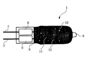
According to the invention, such a lamp 1 is provided with a coating 10 as shown in FIG. 2. This coating 10 has holes 11 in an irregular, random arrangement, for example irregularly shaped defects or cracks. In the illustrated example of embodiment, only the central region of the lamp tube 2 is provided with the coating 10. The sealed tip 9 and the pinch 8 have not been coated.
FIGS. 3 and 4 in each case show microscope images of part of the coating 10, on which the holes 11 can clearly be seen. It can also be seen here that these holes 11 occur in an irregular manner, are irregularly shaped and are of different size.
These holes 11 are produced by setting specific process parameters during the coating operation or in a post-treatment process following the coating operation, wherein the surface density and/or average size are precisely defined by selecting suitable parameters. FIG. 3 shows part of a coating 10 with a surface density and average size of the holes 11 distributed relatively uniformly over the entire surface. FIG. 4 on the other hand shows part of a coating 10 in which, by suitably selecting the process parameters and/or by virtue of the type of post-treatment process, it has been ensured that a higher surface density and greater average size of the holes 11 occurs in certain regions, whereas in other regions there is a lower hole density and smaller average size of the holes 11.
In both cases, these are multilayer coatings with alternating Si and SiO2 layers. The layers have in each case been applied in a so-called MicroDyn sputtering process. This process is a sputtering process in which the plasma is produced not by particle bombardment but rather by microwaves. As a result, even higher densities and higher refractive indices can be achieved than in the conventional ion-assisted vapor-deposition of layers. In particular, there is no diffusion between the individual layers. These lamps coated in this way have then been exposed to a defined thermal post-treatment process.
The process of producing such a lamp 1 is shown once again in FIG. 5 in the form of a flow chart. In a first process step I, a bulb is produced in a conventional manner, for example an H7 halogen bulb as shown in FIG. 1. In process step II, this bulb is then coated. Regions of the lamp which are to be left free of the coating are preferably covered by the lamp holder during the coating operation. In a further process step III, the desired holes are then produced with the defined average surface density and with a defined average size.
In the examples of embodiments shown in FIGS. 3 and 4, the coatings have in each case been heated for 100 hours by a heating device, wherein the temperature is above 600° C. It has been found that at a temperature of 650° C. the number of holes no longer significantly increases after 100 hours. Since the temperature of 650° C. is also above the maximum temperature which can be reached on the tube during operation of the lamp, with these parameters it is also ensured that the holes do not inadvertently expand or the number of holes does not increase during subsequent operation.
For most use purposes, it is sufficient to produce a uniform density distribution and average size as shown in FIG. 3. In principle, however, it is also possible to produce different hole densities and average sizes in some areas, as shown in FIG. 4. For example, a higher hole density may be achieved in the region of the coil than in the other regions if, in addition or as an alternative to external heating, the coil itself is made to glow and thus the temperature of the tube is increased in a targeted manner at this location. FIG. 4 shows the effect after 100 hours of heating by the coil, wherein a temperature of on average 650° C. has likewise been reached in the tube. Since, however, glowing of the coil in the post-treatment process would automatically also lead to a reduction in the service life of the subsequent lamp, purely external heating in a heating device is the preferred measure.
It has been found that the thermal post-treatment of the coating does not have any negative effects on the reflection spectrum. The filter edge is merely shifted towards lower wavelengths.
The coating should therefore preferably be built up such that the filter edge of the coating lies in the range from 830 to 880 nm at an operating temperature of the lamp. The number and size of the holes made is then sufficient to compensate the residual red light in the run-up phase of the lamp. Preferably, the filter edge should lie in the range from 730 to 780 nm in the “cold” state of the lamp. The coating on the lamp reaches a temperature of 600-700° C. approximately three minutes after switch-on. In the process, the filter edge is shifted by 100 nm into the desired range of 830 to 880 nm.
FIG. 6 shows in a highly schematic manner a motor vehicle night vision system 12 in which an infrared lamp according to the invention can be used. The front part of a motor vehicle 13 is schematically shown here. The IR lamp 1 according to the invention is placed in a conventional reflector 14 within a headlamp 15. Of course, the vehicle 13 also has other conventional lamps and headlamp systems such as full beam, low beam, fog lights, etc.
The IR light IR exiting from the infrared lamp 1 according to the invention is emitted via the reflector 14 out of the headlamp 15 in the emission direction A into the traffic space and strikes any object O located in said traffic space. This object O reflects the IR radiation. The reflected IR radiation IRR is detected by an infrared-sensitive camera system 16 which is located in the vehicle 13 for example at the top behind the windscreen. In principle, the IR-sensitive detector used may be a normal CCD or CMOS camera. Such cameras are IR-sensitive anyway, and for use in normal cameras have an IR filter which need only be removed for use in a night vision system. Preferably, a camera system 16 comprising two cameras at a distance from one another may be used in order to be better able to detect spatial information. After suitable processing, the images recorded by the IR camera system 16 can then be displayed to the driver of the motor vehicle 13 on a display (not shown). Automatic evaluation of the data is also possible, so that the driver is notified about objects O located on the road for example by means of acoustic signals or light signals.
In one particularly preferred example of embodiment, in such a motor vehicle night vision system use is made of a lamp 1—as shown in FIG. 2—which does not have any coating in the pinch area 8 and in the region of the sealed tip 9 but is provided with the coating 10 on all of the rest of its surface, said coating having the holes 11 according to the invention. The average surface density of the irregularly occurring holes and the average size thereof are set such that the visible light passing through the holes and the pinch and the sealed tip, together with the amount of visible red light passing through the infrared-transmitting coating, has a spectrum which essentially has a color in the ECE white region. Moreover, the hole size and hole density and the regions left free of the coating in the pinch area and at the sealed tip are selected such that the white light L emitted into the traffic space in the emission direction A is less than 60 candela, particularly preferably less than 50 candela.
Finally, it should be pointed out once again that the methods and lamps shown in the figures and in the description are merely examples of embodiments which can be widely varied by the person skilled in the art without departing from the scope of the invention. For example, further method steps may be added to the method sequence described in detail. Moreover, it should be pointed out for the sake of completeness that the use of the indefinite article “a” or “an” does not rule out the fact that the relevant features may also be present a number of times and that the use of the term “comprise” does not rule out the existence of further elements or steps.

Claims (19)

1. A method of producing an infrared lamp for a vehicle night vision system comprising the acts of:
surrounding a radiation source that emits infrared radiation and light radiation with a tube;
providing an infrared-transmitting coating on the tube including setting specific process parameters in a coating process and/or post-treating the coated tube so that holes form in an irregular arrangement in the infrared-transmitting coating.
2. The method as claimed in claim 1, wherein an average size and the average distribution of the holes are selected such that the light radiation passing through the holes during operation of the lamp has a sufficient intensity to mask an amount of visible red light which is transmitted through the infrared-transmitting coating.
3. The method as claimed in claim 1, wherein certain part-regions of the tube remain without the infrared-transmitting coating and an average size and average distribution of the holes in the coating are selected such that the light radiation passing through the holes during operation of the lamp, together with the light radiation passing through the coating-free part-regions of the tube, has a sufficient intensity to mask an amount of visible red light which is transmitted through the infrared-transmitting coating.
4. The method as claimed in claim 3, wherein the average size of the holes is of between 1 and 20 μm, and the average distribution is approximately 10 to 40 holes per mm2.
5. The method as claimed in claim 1, wherein an average size and average distribution of the holes in the coating and the coating-free part-regions of the tube are arranged such that the light radiation exiting through the holes and the uncoated part-regions during operation of the lamp, mixed with an amount of visible red light which is transmitted through the infrared-transmitting coating, results in light which is white.
6. The method as claimed in claim 1, wherein the providing act includes applying a number of coating layers on top of one another.
7. The method as claimed in claim 1, wherein the coating layers are applied by a sputtering process.
8. The method as claimed in claim 1, further comprising the act of subjecting the coated tube to a defined heating process until a number and an average size of the holes no longer change.
9. The method as claimed in claim 8, wherein the coated tube is kept at a minimum temperature at least until the number and the average size of the holes no longer change.
10. The method as claimed in claim 1, wherein, during the providing act, a defined vacuum is set such that the holes form in the coating.
11. The method as claimed in claim 1, providing act includes building up the coating to form a filter having a pass-band frequency between filter edges such that one filter edge of the filter edges lies in the range from 830 to 880 nm at an operating temperature of the lamp.
12. An infrared lamp for a vehicle night vision system comprising:
a radiation source which emits infrared radiation and light radiation,
a tube which surrounds the radiation source,
and an infrared-transmitting coating which is applied to the tube and which has an irregular arrangement of holes.
13. A headlamp for a vehicle night vision system, comprising an infrared lamp as claimed in claim 12.
14. A headlamp as claimed in claim 13, wherein an average size and an average distribution of the holes in the coating and uncoated part-regions of the tube are designed such that the light radiation exiting through the holes and the uncoated part-regions during operation of the lamp, mixed with the amount of visible red light which is transmitted through the infrared-transmitting coating, results in white light, wherein the light intensity when the light is emitted from the vehicle headlamp in an emission direction is less than approximately 60 candela.
15. The use of an infrared lamp as claimed in claim 12 for a motor vehicle night vision system.
16. The method as claimed in claim 1, wherein an average size of the holes is of between 2 and 8 μm, and an average distribution of the holes is approximately 15 to 25 holes per mm2.
17. The method as claimed in claim 1, wherein the holes are formed by heating the coating by an inhomogeneous temperature distribution.
18. The method as claimed in claim 1, wherein the holes are formed by heating the coating and turning on the lamp so that a greater distribution of holes with a higher average size is achieved in a region of the lamp where the lamp is hotter than in other regions of the lamp.
19. The method as claimed in claim 1, wherein the providing act includes targeted heating of one region of the lamp so that a greater distribution of holes with a higher average size is achieved at the one region of the lamp where the lamp is hotter than in other regions of the lamp.
US11/571,833 2004-07-09 2005-06-24 Method of producing an infrared lamp Expired - Fee Related US7683548B2 (en)

Applications Claiming Priority (4)

Application Number Priority Date Filing Date Title
EP04103275 2004-07-09
EP04103275.6 2004-07-09
EP04103275 2004-07-09
PCT/IB2005/052081 WO2006006091A2 (en) 2004-07-09 2005-06-24 Method of producing an infrared lamp

Publications (2)

Publication Number Publication Date
US20080031003A1 US20080031003A1 (en) 2008-02-07
US7683548B2 true US7683548B2 (en) 2010-03-23

Family

ID=35784239

Family Applications (1)

Application Number Title Priority Date Filing Date
US11/571,833 Expired - Fee Related US7683548B2 (en) 2004-07-09 2005-06-24 Method of producing an infrared lamp

Country Status (6)

Country Link
US (1) US7683548B2 (en)
EP (1) EP1769528A2 (en)
JP (1) JP2008506227A (en)
KR (1) KR20070039131A (en)
CN (1) CN101432845A (en)
WO (1) WO2006006091A2 (en)

Cited By (2)

* Cited by examiner, † Cited by third party
Publication number Priority date Publication date Assignee Title
US20090081619A1 (en) * 2006-03-15 2009-03-26 Israel Aircraft Industries Ltd. Combat training system and method
US8816306B2 (en) 2011-12-15 2014-08-26 Battelle Memorial Institute Infrared light device

Families Citing this family (11)

* Cited by examiner, † Cited by third party
Publication number Priority date Publication date Assignee Title
JP4714108B2 (en) * 2006-08-09 2011-06-29 株式会社小糸製作所 Infrared light irradiation lamp for vehicles
JP2008041571A (en) 2006-08-09 2008-02-21 Koito Mfg Co Ltd Infrared irradiation lamp for vehicle
US7345414B1 (en) * 2006-10-04 2008-03-18 General Electric Company Lamp for night vision system
US8046438B2 (en) * 2007-03-16 2011-10-25 Yahoo! Inc. System and method of restoring data and context of client applications stored on the web
US8046436B2 (en) * 2007-03-16 2011-10-25 Yahoo! Inc. System and method of providing context information for client application data stored on the web
US8041781B2 (en) * 2007-03-16 2011-10-18 Yahoo! Inc. System and method for providing web system services for storing data and context of client applications on the web
WO2008125611A1 (en) * 2007-04-16 2008-10-23 Osram Gesellschaft mit beschränkter Haftung Method for the aftermarket removal or modification of an outer glass coating on a light bulb, and lamp produced by such a method
EP2083347A3 (en) * 2008-01-21 2011-04-27 Crucial Tec Co., Ltd. Optical input device and portable electronic device having the same
KR20120002575A (en) * 2009-02-27 2012-01-06 코닌클리즈케 필립스 일렉트로닉스 엔.브이. Led-based lamps and thermal management systems therefor
FR3090073B1 (en) * 2018-12-12 2022-10-07 Valeo Vision Motor vehicle light module
CN114525493A (en) * 2022-01-13 2022-05-24 苏州科技大学 Metamaterial infrared emission structure and preparation method

Citations (6)

* Cited by examiner, † Cited by third party
Publication number Priority date Publication date Assignee Title
EP0686998A1 (en) 1994-06-06 1995-12-13 General Electric Company Light source
US5676579A (en) * 1993-12-10 1997-10-14 General Electric Company Patterned optical interference coatings for electric lamps
EP0947763A2 (en) 1998-03-25 1999-10-06 Du Pont-Toray Company, Ltd. Reflector substrate for illumination device and reflector for illumination device
US20020154515A1 (en) 2001-04-24 2002-10-24 Koito Manufacturing Co., Ltd. Infrared irradiation lamp for automobile
US20030007363A1 (en) * 2001-07-06 2003-01-09 Koito Manufacturing Co., Ltd. Automotive infrared lamp
US6601980B2 (en) * 2000-02-15 2003-08-05 Koito Manufacturing Co., Ltd. Infrared-ray radiating lamp for automobile

Family Cites Families (1)

* Cited by examiner, † Cited by third party
Publication number Priority date Publication date Assignee Title
CN100375221C (en) * 2002-07-23 2008-03-12 皇家飞利浦电子股份有限公司 Lamp

Patent Citations (6)

* Cited by examiner, † Cited by third party
Publication number Priority date Publication date Assignee Title
US5676579A (en) * 1993-12-10 1997-10-14 General Electric Company Patterned optical interference coatings for electric lamps
EP0686998A1 (en) 1994-06-06 1995-12-13 General Electric Company Light source
EP0947763A2 (en) 1998-03-25 1999-10-06 Du Pont-Toray Company, Ltd. Reflector substrate for illumination device and reflector for illumination device
US6601980B2 (en) * 2000-02-15 2003-08-05 Koito Manufacturing Co., Ltd. Infrared-ray radiating lamp for automobile
US20020154515A1 (en) 2001-04-24 2002-10-24 Koito Manufacturing Co., Ltd. Infrared irradiation lamp for automobile
US20030007363A1 (en) * 2001-07-06 2003-01-09 Koito Manufacturing Co., Ltd. Automotive infrared lamp

Cited By (3)

* Cited by examiner, † Cited by third party
Publication number Priority date Publication date Assignee Title
US20090081619A1 (en) * 2006-03-15 2009-03-26 Israel Aircraft Industries Ltd. Combat training system and method
US8632338B2 (en) * 2006-03-15 2014-01-21 Israel Aircraft Industries Ltd. Combat training system and method
US8816306B2 (en) 2011-12-15 2014-08-26 Battelle Memorial Institute Infrared light device

Also Published As

Publication number Publication date
WO2006006091A3 (en) 2009-03-19
CN101432845A (en) 2009-05-13
JP2008506227A (en) 2008-02-28
KR20070039131A (en) 2007-04-11
EP1769528A2 (en) 2007-04-04
WO2006006091A2 (en) 2006-01-19
US20080031003A1 (en) 2008-02-07

Similar Documents

Publication Publication Date Title
US7683548B2 (en) Method of producing an infrared lamp
US20090175043A1 (en) Reflector for lighting system and method for making same
US5676579A (en) Patterned optical interference coatings for electric lamps
US7829191B2 (en) Lens for lighting system
US20080116780A1 (en) Lamp
US20080129174A1 (en) Nir Incandescent Lamp
US20090167182A1 (en) High intensity lamp and lighting system
JPS5924489B2 (en) high intensity lamp
US7183712B2 (en) Lamp for a vehicle headlight with low-beam function
CN101878516A (en) The IR reflecting grating that is used for lamp
JPH10512095A (en) Reflective light
JP2006517328A (en) Lamp and lighting unit with shading mechanism and interference coating for improving color temperature uniformity
US20090168445A1 (en) Covert filter for high intensity lighting system
EP1170771A1 (en) Cathode ray tube and method for manufacturing thereof
WO2006097863A1 (en) Halogen lamp
CN102754024B (en) Discharge tube and stroboscopic device
JP2004527881A (en) Improved plasma lamp and method
JP2006037073A (en) Composition for opaque coating, lamp with coating, and method for manufacturing the same
JPH0945295A (en) Incandescent lamp, reflection type lighting system using same, and vehicle headlight
JP2657603B2 (en) Manufacturing method of automotive lighting
JP3054664B2 (en) Multilayer reflector
JP3103397U (en) Automotive lighting
GB2313706A (en) A process for forming patterned optical interference coatings for electric lamps
JP2004014273A (en) Color lamp and its manufacturing method
Küpper et al. Coating Technology of Automotive Bulbs

Legal Events

Date Code Title Description
AS Assignment

Owner name: KONINKLIJKE PHILIPS ELECTRONICS N V, NETHERLANDS

Free format text: ASSIGNMENT OF ASSIGNORS INTEREST;ASSIGNORS:KUPPER, LUKAS;KNIGHT, COLETTE;REEL/FRAME:018729/0258

Effective date: 20050627

Owner name: KONINKLIJKE PHILIPS ELECTRONICS N V,NETHERLANDS

Free format text: ASSIGNMENT OF ASSIGNORS INTEREST;ASSIGNORS:KUPPER, LUKAS;KNIGHT, COLETTE;REEL/FRAME:018729/0258

Effective date: 20050627

REMI Maintenance fee reminder mailed
LAPS Lapse for failure to pay maintenance fees
STCH Information on status: patent discontinuation

Free format text: PATENT EXPIRED DUE TO NONPAYMENT OF MAINTENANCE FEES UNDER 37 CFR 1.362

FP Lapsed due to failure to pay maintenance fee

Effective date: 20140323