US7679727B2 - Method and system for determining the position of a receiver unit - Google Patents
Method and system for determining the position of a receiver unit Download PDFInfo
- Publication number
- US7679727B2 US7679727B2 US11/914,723 US91472306A US7679727B2 US 7679727 B2 US7679727 B2 US 7679727B2 US 91472306 A US91472306 A US 91472306A US 7679727 B2 US7679727 B2 US 7679727B2
- Authority
- US
- United States
- Prior art keywords
- radiation
- reference points
- set forth
- receiver unit
- phase
- Prior art date
- Legal status (The legal status is an assumption and is not a legal conclusion. Google has not performed a legal analysis and makes no representation as to the accuracy of the status listed.)
- Active
Links
- 238000000034 method Methods 0.000 title claims abstract description 60
- 230000005855 radiation Effects 0.000 claims abstract description 83
- 238000001514 detection method Methods 0.000 claims abstract description 10
- 238000005259 measurement Methods 0.000 claims description 46
- 230000008859 change Effects 0.000 claims description 17
- 230000003287 optical effect Effects 0.000 claims description 11
- 230000005670 electromagnetic radiation Effects 0.000 claims description 6
- 238000011156 evaluation Methods 0.000 claims description 6
- 238000004891 communication Methods 0.000 claims description 5
- 239000000835 fiber Substances 0.000 claims description 3
- 230000008878 coupling Effects 0.000 claims description 2
- 238000010168 coupling process Methods 0.000 claims description 2
- 238000005859 coupling reaction Methods 0.000 claims description 2
- 238000012512 characterization method Methods 0.000 claims 1
- 238000010586 diagram Methods 0.000 description 17
- 238000013459 approach Methods 0.000 description 12
- 238000010276 construction Methods 0.000 description 10
- 230000000875 corresponding effect Effects 0.000 description 7
- 238000013461 design Methods 0.000 description 6
- 230000005540 biological transmission Effects 0.000 description 4
- 230000001419 dependent effect Effects 0.000 description 4
- 239000011888 foil Substances 0.000 description 4
- 238000012545 processing Methods 0.000 description 4
- 238000000926 separation method Methods 0.000 description 3
- 238000004458 analytical method Methods 0.000 description 2
- 230000007613 environmental effect Effects 0.000 description 2
- 230000002349 favourable effect Effects 0.000 description 2
- 230000008569 process Effects 0.000 description 2
- 238000002271 resection Methods 0.000 description 2
- 230000000007 visual effect Effects 0.000 description 2
- 241001422033 Thestylus Species 0.000 description 1
- 230000001133 acceleration Effects 0.000 description 1
- 230000033228 biological regulation Effects 0.000 description 1
- 230000015572 biosynthetic process Effects 0.000 description 1
- 238000004364 calculation method Methods 0.000 description 1
- 230000002301 combined effect Effects 0.000 description 1
- 230000002596 correlated effect Effects 0.000 description 1
- 239000013078 crystal Substances 0.000 description 1
- 230000001934 delay Effects 0.000 description 1
- 230000003111 delayed effect Effects 0.000 description 1
- 238000009795 derivation Methods 0.000 description 1
- 230000000694 effects Effects 0.000 description 1
- 238000005516 engineering process Methods 0.000 description 1
- 238000009499 grossing Methods 0.000 description 1
- 210000004209 hair Anatomy 0.000 description 1
- 239000004973 liquid crystal related substance Substances 0.000 description 1
- 238000004519 manufacturing process Methods 0.000 description 1
- 230000000873 masking effect Effects 0.000 description 1
- 239000000463 material Substances 0.000 description 1
- 238000001208 nuclear magnetic resonance pulse sequence Methods 0.000 description 1
- 239000003973 paint Substances 0.000 description 1
- 230000010287 polarization Effects 0.000 description 1
- 230000000750 progressive effect Effects 0.000 description 1
- 230000000135 prohibitive effect Effects 0.000 description 1
- 230000000644 propagated effect Effects 0.000 description 1
- 238000005086 pumping Methods 0.000 description 1
- 238000005096 rolling process Methods 0.000 description 1
- 239000004065 semiconductor Substances 0.000 description 1
- 230000035945 sensitivity Effects 0.000 description 1
- 230000006641 stabilisation Effects 0.000 description 1
- 238000011105 stabilization Methods 0.000 description 1
- 230000001629 suppression Effects 0.000 description 1
- 230000009466 transformation Effects 0.000 description 1
- 230000001960 triggered effect Effects 0.000 description 1
- 239000013598 vector Substances 0.000 description 1
Images


Classifications
-
- G—PHYSICS
- G01—MEASURING; TESTING
- G01S—RADIO DIRECTION-FINDING; RADIO NAVIGATION; DETERMINING DISTANCE OR VELOCITY BY USE OF RADIO WAVES; LOCATING OR PRESENCE-DETECTING BY USE OF THE REFLECTION OR RERADIATION OF RADIO WAVES; ANALOGOUS ARRANGEMENTS USING OTHER WAVES
- G01S17/00—Systems using the reflection or reradiation of electromagnetic waves other than radio waves, e.g. lidar systems
- G01S17/87—Combinations of systems using electromagnetic waves other than radio waves
- G01S17/875—Combinations of systems using electromagnetic waves other than radio waves for determining attitude
-
- G—PHYSICS
- G01—MEASURING; TESTING
- G01C—MEASURING DISTANCES, LEVELS OR BEARINGS; SURVEYING; NAVIGATION; GYROSCOPIC INSTRUMENTS; PHOTOGRAMMETRY OR VIDEOGRAMMETRY
- G01C15/00—Surveying instruments or accessories not provided for in groups G01C1/00 - G01C13/00
- G01C15/002—Active optical surveying means
-
- G—PHYSICS
- G01—MEASURING; TESTING
- G01S—RADIO DIRECTION-FINDING; RADIO NAVIGATION; DETERMINING DISTANCE OR VELOCITY BY USE OF RADIO WAVES; LOCATING OR PRESENCE-DETECTING BY USE OF THE REFLECTION OR RERADIATION OF RADIO WAVES; ANALOGOUS ARRANGEMENTS USING OTHER WAVES
- G01S5/00—Position-fixing by co-ordinating two or more direction or position line determinations; Position-fixing by co-ordinating two or more distance determinations
- G01S5/16—Position-fixing by co-ordinating two or more direction or position line determinations; Position-fixing by co-ordinating two or more distance determinations using electromagnetic waves other than radio waves
- G01S5/163—Determination of attitude
Definitions
- the invention relates to a method for determining the position of a receiver unit and a system for determining the position.
- An example of location determination systems is global positioning systems, such as, for example, GPS, GLONASS or the European Galileo system currently being set up. These systems are based on as far as possible undisturbed reception of satellite signals, which however may also be obstructed by obstacles and therefore limited in their usability. Owing to their shading effect, the reception of signals may be limited or completely impossible in the immediate vicinity of obstacles, so that a location determination is no longer possible with this system. These limitations relate in particular to measurements in interior rooms of buildings in which the reception of a number of satellites which is required for positioning can generally be ruled out. A further problem is that global positioning systems do not always provide the required accuracy of position determination or require greater effort, for example through the use of a reference station or longer measuring times.
- a further example is the determination of the location of a reflector-carrying instrument with a theodolite or tacheometer.
- a direction or distance measurement with the tacheometer to the geodetic instrument it is also possible to determine the location of the instrument if the location of the tacheometer is known.
- a quasi-continuous location determination can be achieved.
- a precondition for the measurement here is the line of sight between the two components. If this single link is interrupted, for example by foliage or buildings in the field of view, the method of location determination fails.
- So-called robotic total station systems which are operated from the level pole or plumb rod constitute a customary variant.
- Such one-man operation devices are commercially available and are offered by many manufacturers.
- the automated theodolite supported as a rule by a video camera serves as a fixing station which optically tracks the hand-held level pole or plumb rod.
- the coordinates of the target point are calculated at the central station, transmitted to the sighting unit and displayed there.
- These devices too, all have the disadvantage that a direct line of sight to the level pole or plumb rod is essential.
- dynamic tracking has additional disadvantages since the fixing station can lose the target in the case of large accelerations.
- the determination of the actual location or actual orientation is effected by a measurement to the reference points and/or further measurements, for example an inclination measurement, and hence relative to the perpendicular or horizontal, from which the actual location or the actual orientation can be derived.
- location and/or orientation can in principle be determined absolutely, i.e. by an isolated measurement to points of known location, or relatively, i.e. with observation of the change of known location or orientation relative to a zero position.
- a geodetic instrument has only a capability of distance measurement or measurement of angles cannot be carried out with the required precision or speed.
- the location determination must be carried out only by distance measurements.
- the distances to a plurality of points having a known location are measured, and the actual position can be determined by known methods, as are also used, for example, in photogrammetry. Correlation methods or correlation calculations are an example of this.
- the number of required points is dependent on the position thereof and the intended accuracy of the measurement. As a rule, however, apart from particularly favorable configurations, at least 3 or 4 points are required. If an angle is additionally taken into account, for example by additionally determining the angle relative to the horizontal, the number of points can be reduced to two.
- the number of points actually required in each case is dependent on the position of the known points and any possible limitations for reducing an ambiguity.
- the three known locations define a plane at which the actual position to be determined can be reflected.
- the resulting solution comprises two possible locations, one of which, however, is generally ruled out for plausibility reasons, for example because it would lie below the Earth's surface, or on the basis of other simple information, such as, for example, the distinction between North and South, which can also be made by a simple magnetic compass.
- An unambiguous determination with three known points is possible if favorable geometric conditions are present. This is the case, for example, if the location sought lies on a connecting line between two known points.
- PCT/EP2004/010571 discloses a system for determining the actual position of a measuring device, in which at least two reference points located in a spatial segment scanned by means of a laser beam are detected and are measured with respect to their distance and their angle of inclination. From the known locations of these reference points designed to be detectable and the coordinated distances and angles of inclination, the actual location of the measuring device can be derived. The detection, tracking and surveying of the reference points are carried out in an automated manner by the measuring device, the measuring device and the reference points forming coordinated, specially formed elements of a local positioning and/or orientation measurement system.
- the reference points must be actively scanned by means of a laser beam and must be illuminated, so that the reception component in the measuring device has to have a very complex design.
- transmitter and receiver are placed in a single device and linked structurally to one another so that, for example, it is not possible for a plurality of receivers to use the light of a common, central transmitter, which is in fact due to the passive design, i.e. only in reflection of the light signal emitted by the measuring device.
- this design limits the number of usable reference points since these can be scanned only within the emission cone of the transmitter present in the measuring device and furthermore sequentially.
- the objective reference points must be mounted and measured before the measurement, which requires a certain effort or is impossible in some regions.
- a reference point may present problems under certain circumstances since a reference point is not always unambiguously detectable during a scanning movement, for example if the laser beam strikes a shiny object, which can then be inadvertently interpreted as a reference point.
- An apparatus from U.S. Pat. No. 6,381,006 comprising 3 reference stations which emit laser radiation in a fan shape is also known.
- the system is operated from the level pole or plumb rod.
- the spatial coordinates are defined by the 3 emitted light fan beams.
- 3 Direction sensors which survey the position of the level pole or plumb rod in space by means of the light fan beams are present on the hand-held level pole or plumb rod. The location at the target point is therefore determined.
- the level pole or plumb rod is also equipped with a reflectorless distance meter.
- the apparatus has the disadvantage that there is the requirement for a line of sight simultaneously to 3 reference stations, which have to be placed as a rule at eye level. This precondition is scarcely fulfilled in the building sector or on building sites with traffic.
- the technical design of the reference stations is complex, the effort being further increased by the requirement for a multiplicity of such stations.
- a further spatial position system having likewise rotating light fan beams is disclosed in the documents U.S. Pat. Nos. 6,545,751 and 6,646,732.
- the 3D coordinate determination of a hand-held sighting unit, which is described there, is based on time or interval measurement of in each case at least 2 light fan beams emitted by a fixing station.
- These apparatuses likewise have the disadvantage that there must be a line of sight between the hand-held sighting unit and the at least 2 reference stations. In this approach, too, a great effort and high complexity are required.
- An object of the present invention is to provide a simplified method and an apparatus or a system of reduced complexity which permits a determination of the actual location and of the orientation of a hand-held measuring device even in strongly transected terrain or in interior rooms.
- a further object is to simplify or to improve the handling in the case of the setting up of such a system and the components thereof.
- the invention relates to a method for determining a location and/or an orientation of a receiver unit and a system for determining a location and/or an orientation.
- the approach according to the invention is based on the fact that the direct positioning of radiation sources or objects which can be illuminated by such sources can be replaced by a projection of reference points.
- a set of detectable radiation or light spots is produced by one or more projection units and said spots are detected and evaluated as reference points by a receiving unit. Both relative and absolute positionings of orientation determinations can be carried out.
- the means for producing reference points and the receiving unit can be positioned independently of one another so that a set of fixed reference points is provided by the means for producing reference points, relative to which reference points the receiving unit is oriented or is determined in its orientation or location.
- the transmitter irradiates the diffusely reflecting or partly reflective object, and the reference objects form only as a result of the light spot on the object.
- a plurality of laser beams results in the formation of a correspondingly large number of reference points, i.e. the number of reference points is determined by the number of laser projections, the projection units in turn being independent of the measuring device or of the receiving unit, and in theory being as large as desired. Consequently, the availability of the reference points is high, and the projection unit or the totality thereof can continuously produce the corresponding reference points on the object.
- the space to be surveyed is transected or “flooded” with detectable radiation from a plurality of radiation projectors or—depending on the specific design of the source—from one or more corresponding multi-transmitter units or a multiple laser projector as means for producing reference points.
- the means for producing reference points which can preferably be in a form of a multi-transmitter unit, act as a reference station, constitute a sort of laser projector.
- the number of emitted laser beams is at least 3, but typically 4 laser units or projections of reference points are present.
- a number of detectable reference points which is predetermined by the existing constraints and environmental conditions and the desired accuracy of measurement must always be present for the receiver unit.
- the total set of reference points to be projected may also be less than 3 or substantially greater than 4.
- the projection can be produced by a single multi-transmitter unit or by a plurality of such units, it being possible for the units to have a communication link to one another.
- the radiation of a common source can also be transmitted and projected via a relay station.
- the reference points can in principle be projected simultaneously, but also in sequence at an appropriately high rate, this, however, advantageously being chosen so that a progressive, i.e. continuous or uninterrupted, optical link between the receiving unit and the projected reference points can be maintained.
- the detection of the reference points can also be effected for a plurality of reference points, i.e. in particular 3 reference points, simultaneously or at an appropriately high rate for maintaining the optical link.
- the light to be projected is moreover modulated with high frequency, in particular intensity-, phase- or polarization-modulated, it being possible for the radiation to be in the visible as well as in the infrared wavelength range or in even longer-wave ranges.
- the preferably collimated and emitted light beams strike stationary surfaces and are reflected by them into space, in particular into the region to be surveyed.
- the reflection may be diffuse or directed, it being possible for the reflecting surfaces to be natural surfaces, such as, for example, walls of a room to be surveyed, reflective areas, such as, for example, window fronts, or special reflective marks simulating satellites or special reflective materials which can be set up or mounted at suitable points. Marks having a transmissive or combined effect can also be realized.
- the laser units or radiation projectors emit modulated radiation, for example the modulated light of the 3 or more transmission units being coupled rigidly to one another with respect to phase.
- the associated information is formed in such a way that mm-accurate or even sub-mm-accurate distance information can be determined from the transit time or phase position of the modulation, which may be considered as a typical measure for the required accuracy of geodetic measurement.
- the laser beams are modulated and are coupled to one another rigidly with respect to phase or with respect to time and transmit the transit time or phase from the laser projector via the objects forming reference points to the receiver, which is spatially separated from the transmitter.
- the link to the reflective object is or can be at least permanently maintained.
- the entire room to be surveyed is continuously flooded with measuring light.
- the availability of the distance information is therefore great in comparison with a scanning and searching movement.
- the laser light scattered by the satellites, reference points or walls, produced by these 3, typically 4, transmission units, is detected. From the relative transit times or phase positions of the modulation forms, the location of the detector can be calculated.
- the reference points are positioned so that they can be seen from that region of the room which is to be surveyed.
- the protection also makes it possible to produce the reference points at elevated areas so that good detectability is ensured.
- the projection can take place onto suitable structures which are in any case present, such as, for example, ceilings of interior rooms, or onto special objects.
- objects are, for example, spheres or reflective panels which can be adhesively bonded to natural surfaces and can be set up so as to be visible by means of an extendable rod system.
- the location or orientation determination is effected either relative to an assigned zero position whose position is known or absolutely.
- the measuring device with the receiver unit is positioned at the location of the zero position at the beginning of the method and the radiation of the reference points is detected and measured. If the coordinates of the reference points are known, this can be effected by a prior measurement; thus, the relative location or orientation determination can be begun directly on the receiver side.
- the drift relative to the zero position is determined from the change in characteristics superposed on the radiation or modulated.
- the location of the reference points can be determined by a resection method.
- the hand-held receiver unit is positioned according to the location of the zero position preferably at one, two or three further known locations which, together with the zero position, define the direction and length of the unit vectors of the one-, two- or three-dimensional coordinate system.
- the approach for absolute positioning or orientation is thus based on a knowledge of the position of the detected reference points, so that these must be measured beforehand or must be positioned at points known with respect to their position. From a knowledge of the absolute location of the reference points, the distances thereof from the laser projector and the received modulated signals, the absolute location or orientation of the receiver unit can be derived.
- Both the measurement of the absolute position and the relative position determination include the analysis of the radiation originating from reference points with regard to distance information, either the distance itself or the change in a distance being considered.
- distance-measuring methods such as phase measurement or transit time measurement, for example the relative position, as a function of time, of a signal superposed on the radiation or a phase segment forming the basis of the measurements.
- a first approach according to the invention for signal processing of the received radiation is based on the phase measurement principle, the principle resembling the GPS surveying method.
- the GPS method it is not the phase of the one carrier signal but that of the intensity or polarization modulation of the laser light that is measured and is evaluated in the manner of a conventional distance meter according to the phase measurement principle.
- each laser source can be modulated with its own frequency.
- the following frequencies are expedient for distinguishing the individual transmitters: 33 MHz, 31 MHz, 29 MHz, 27 MHz.
- the signal received at the receiver unit can then be divided according to frequencies and the phases thereof can be individually determined.
- the receiver unit measures the phase of the radiation scattered by the reflection points. By means of a clock signal which is generated by a local oscillator with crystal accuracy as standard time, the measurement of the phase of the signals coordinated with the transmission units is effected. If the receiver unit is provided with an atomic clock, 3 modulated transmitted signals are sufficient; for the case of a less accurate standard time in the case of the receiver unit, at least 4 modulated transmitted signals are required in order to achieve a location determination with mm accuracy.
- the heterodyne method customary in phase distance measurement can also be used for the frequency transformation. This makes it possible to realize the phase measurement on low-frequency signals by means of digital electronic modules and evaluation methods.
- the absolute phases (ambiguity resolution, number of modulation wavelengths) and hence the distances to the satellites and finally the location (3 coordinates x, y, z) of the receiver unit can be determined by the known methods of signal evaluation of GPS systems.
- the number of modulation wavelengths at which two frequencies simultaneously or one frequency with phase scanning are modulated on the carrier light can be derived, for example, by means of bimodulation.
- a second approach according to the invention can be realized by the method of pulsed transit time measurement.
- Light pulses are emitted by the laser gun and in turn are mutually delayed with respect to time and are rigidly coupled to one another.
- the unambiguity range and hence the measuring range of the apparatus can be from several 100 m to 1000 m.
- the identification of the reference points or reflection points can in turn be permitted by different carrier or light wavelengths. In the simplest case, these can be masked by ensuring that the light pulses occur in succession as a function of time.
- time intervals are coordinated with the individual laser sources or satellites.
- One of the pulses can additionally be provided with a coding feature for identification of the beginning of the sequence. For example, a longer light pause is attached to the last pulse before the pulse sequence is repeated beginning with the first pulse.
- the identification of the individual laser sources is likewise possible as an incremental method by means of a continuous detection and analysis of the delay of the individual pulses.
- this approach has fundamental problems if the beam is interrupted.
- the transit time measurement has advantages such as, for example, higher sensitivity, higher measuring speed, longer range, but in particular the greater robustness with respect to ambient light.
- a frequency synthesizer is easier to realize since a single pulse frequency is sufficient for all laser sources.
- FIG. 1 shows the diagram of a first use example for the method according to the invention for determining the location of a construction machine
- FIG. 2-3 show the diagram of a second use example for the method according to the invention for determining the location of a construction machine
- FIG. 4-6 show the diagram of a third use example for the method according to the invention for determining the location of a hand-held measuring device
- FIG. 7 a - d show the diagram of working examples of the radiation projector according to the invention.
- FIG. 8 shows the diagram of the signal curves as a function of time for the method according to the invention based on the transit time measuring principle
- FIG. 9 shows the diagram of the method according to the invention based on the phase measuring principle with measurement and determination of the relative phases
- FIG. 10 shows the diagram of the method according to the invention based on the phase measuring principle with measurement of the absolute phases
- FIG. 11 shows the diagram of a first working example of the receiver unit according to the invention.
- FIG. 12 shows the diagram of a second working example of the receiver unit according to the invention.
- FIG. 13 a - b show the diagram of a third working example of the receiver unit according to the invention.
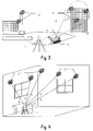
- FIG. 1 shows, by way of example, a first use example for the method according to the invention for determining the position of a construction machine 4 .
- the construction machine 4 is present in a trench, so that direct sighting by a centrally placed unit, such as, for example, by at total station, is not possible.
- a set of reference points 2 which in turn can be detected by the construction machine 4 , is projected by a radiation projector 1 .
- electromagnetic radiation S preferably laser light
- special components such as, for example, the projection panels 3 shown here purely by way of example.
- These projection panels 3 may have, for example, a white or spectrally optimized surface which is arranged on a stand so as to be extendible. By means of a plurality of such projection panels 3 , coverage of the processing region can be achieved.
- FIG. 2-3 show the diagram of a second use example for the method according to the invention for determining the location of a construction machine 4 .
- natural surfaces can also be used instead of the projection panels of the first working example, it also being possible, if appropriate, for said natural surfaces to be adapted in their back-radiating characteristic by special treatment, such as, for example, smoothing, or the mounting of components, such as, for example, mirror foils or reflector foils, reflective paint or spheres.
- the radiation projector 1 now projects the electromagnetic radiation S onto existing structures and thus produces a set of reference points 2 ′.
- spheres can be illuminated by means of a collimated laser beam so that a relatively large part of the space is illuminated by the reflected radiation.
- beam diameter and sphere diameter are tailored to one another.
- the special components such as, for example, the projection panels of FIG. 1 , and natural structures together.
- FIG. 3 explains the determination of the position of the construction machine 4 on the basis of the projected reference points 2 ′.
- Those reference points 2 ′ of the set of the reference points which are within the detection region 6 of a receiver unit 5 are detected by the construction machine 4 .
- the number of reference points 2 ′ required for determining the position i.e. location and/or orientation, is dependent on the desired accuracy and on possible limitations of the degrees of freedom by specified information or constraints, for example movement on a horizontal surface without irregularities. In general, however, four reference points 2 ′ are required for determining the position of the receiver unit 5 and hence of the construction machine 4 in a manner similar to a global positioning system.
- FIG. 4-6 contain the diagram of a third use example for the method according to the invention for determining the location of a hand-held measuring device in the interior of a building.
- a radiation projector 1 ′ is set up in a room in the interior of a building so that said projector is capable of projecting a set of a plurality of reference points 2 ′′ onto the wall with the radiation S generated by it.
- a subset of these reference points 2 ′′ is detected by the detection region 6 ′ of a receiver unit 5 ′ so that, as shown in FIG. 5 , radiation projector 1 ′ and receiver unit 5 ′ are linked via the distance covered by the radiation. If the coordinates of radiation projector and reference points are known, the position of the receiver unit 5 ′ can in principle be derived from the knowledge of these distances or of the distance segments from reference point 2 ′′ to the receiver unit 5 ′. The coordinates of radiation projector and reference points can be determined, for example, as part of the setup process by means of a theodolite.
- the receiver unit 5 ′ If a determination of the relative location or orientation of the receiver unit 5 ′ is effected, the receiver unit is positioned beforehand in a known zero position NL at the beginning of the procedure, as shown in FIG. 6 . In this zero position NL, an initial measurement to the reference points 2 ′′ is effected. After initial measurement is complete, the actual measuring tasks are carried out, the receiver unit 5 ′ being moved to the respective measuring position ML. In the case of a relative position determination, the receiver unit 5 ′ tracks the change of signals superposed on the radiation with respect to the characteristic of these signals in the zero position NL.
- the method requires a calibration body which fixes the coordinates in the space to be surveyed.
- a defined, i.e. measured or surveyed, variable e.g. a meter rule
- the receiver unit 5 ′ measures the distances covered by the radiation, at least at the two end points.
- the zero position NL of the relative location of the receiver unit 5 ′ is then given, for example, by the first end of the meter rule, and the coordinate direction and unit length by the second end.
- the calibration with three defined variables in three orthogonal directions is advantageous, so that a calibration body is defined thereby.
- the unit lengths it is also possible to use an apparatus within the device.
- a movement relative to a surface can be registered and surveyed.
- a calibration of the movement of the receiver unit 5 ′ is then effected from the measured distance relative to the surface and the change of the coordinated measurements to the reference points 2 ′′.
- FIG. 7 a - d show diagrams of working examples of the radiation projector according to the invention.
- FIG. 7 a shows a first working example of the radiation projector according to the invention, the projector body 7 having a radiation-permeable cover 8 within which four radiation sources 9 a - d are arranged so as to be individually adjustable.
- the radiation S generated by these radiation sources 9 a - d can be aligned manually or automatically for projecting reference points onto suitable objects.
- FIG. 7 b shows a second working example of the radiation projector according to the invention, comprising an element 10 for scanning beam guidance as a projection means.
- the radiation S of the radiation source 9 e is now projected as a function of time to various locations for producing the set of reference points.
- the scanning movement can be realized both by classical mechanical components and, for example, by microelectromechanical (MEMS) technology.
- MEMS microelectromechanical
- the radiation projector itself can be equipped with a distance-measuring and angle-measuring device. This simplifies the setup of the system which is necessary for an absolute location determination.
- the measurement of the positioning system can, however, also be carried out by using a surveying instrument, such as, for example, a theodolite.
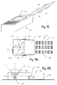
- the beam source 9 f used is a pulsed microchip laser, the radiation of which is passed over a plurality of delay lines 11 a - c .
- the orientation of the radiation to be emitted and the projection thereof are effected by means of a plurality of orientation components 12 a - d as projection means.
- Suitable microchip lasers emit over 1 kW as a peak pulse power at a pulse duration of 1 ms.
- the laser light produced is then coupled into four parallel single-mode fibers of, for example, 1 m, 101 m, 201 m and 301 m length as delay lines, so that a mutual time-related distance of about 500 ns results, which corresponds to a spatial separation of about 150 m.
- the light passed via the fibers is then collimated by either a scanning element or the orientation components 12 a - d as projection means, and the reference points are projected. Owing to the common source, coupling of the four emitted signals takes place, an identical signal characteristic being ensured. For example, 10 kHz can be chosen as the repetition rate of the microchip laser, a certain stabilization being effected via the pumping power or a temperature regulation.
- FIG. 7 d shows a fourth working example in which a delay is effected in a manner similar to FIG. 7 c .
- the light of a beam source 9 g is coupled into a common delay line lid, from which, after appropriate distances, in each case a part of the radiation is coupled out by optical splitters or couplers and projected via a coordinated unit of the orientation components 12 a - d as projection means.
- FIG. 8 shows the signal curves as a function of time for the method according to the invention, based on the transit time measuring principle.
- variables are plotted as a function of time.
- the ppm-accurate standard time of the receiver unit is shown as a square-wave signal.
- the received signals from four reference points are shown underneath.
- the signals emitted as laser pulses have a pulse repetition time T Rep , a time window—for example due to the use of delay lines—existing on the transmitter and receiver side for each laser.
- the duration of the time windows T Laser1 -T Laser4 is identical.
- the receiver unit Based on the time zero point t 0 , the receiver unit receives four pulses at the times t 1 -t 4 , to which a transit time t 1 ′-t 4 ′ corresponds within the respective time window. These signal curves as a function of time are recorded by the receiver unit in the zero position, and the change, i.e. the change of the times t 1 -t 4 or transit times t 1 ′-t 4 ′, relative to this profile is evaluated continuously for position determination.
- a corresponding distance can be coordinated with each transit time t 1 ′-t 4 ′.
- the change of the distances is correlated with a change in location of the receiver unit, so that a change in location or in orientation can be derived. Both the complete distance to the reference point or to the radiation source and only the change of the distance can be evaluated.
- FIG. 9 An alternatively possible method according to the invention based on the phase measuring principle with measurement of the relative phases is shown in FIG. 9 .
- the change of the signal characteristic relative to a zero position NL is determined and evaluated for a receiver unit 5 ′ at the location of a measuring position.
- consideration is given to a phase difference PD 1 or PD 2 which, for reasons of clarity, are shown purely by way of example only for two reference points 2 ′′′. If the phase differences increase over a full cycle, i.e. 2 ⁇ , these must also be included, since otherwise the relationship with the zero position NL is lost.
- FIG. 10 shows the diagram of the method according to the invention based on the phase measuring principle with determination of the absolute phases.
- phase segments are measured, i.e. relative phases from 0 to 2 ⁇ .
- the absolute phase is calculated therefrom by resolution of the phase ambiguity.
- the absolute phase AP 1 or AP 2 for the reference points 2 ′′′ is now determined instead of the relative phase. This comprises a resolution of the phase ambiguity which is known from the area of global positioning systems.
- the distance to the reference point 2 ′′′ or to the radiation source is then also defined thereby.
- a determination of the absolute location may also be permitted if, in addition to the location of the radiation source, the position P 1 (x 1 , y 1 , z 1 ) or P 2 (x 2 , y 2 , z 2 ) of the reference points 2 ′′′ is also known, so that the directions coordinated with the distances D 1 and D 2 can be determined.
- This approach then substantially corresponds to the location determination by means of satellites, the reference points serving so to speak as artificial satellites or stars.
- an absolute position determination can also be effected without prior measurement from a zero position, but this approach requires a knowledge of the position P 1 (x 1 , y 1 , z 1 ) or P 2 (x 2 , y 2 , z 2 ) of the reference points, which requires either their projection at known locations or prior surveying of the projections.
- FIG. 11 The realization of a first receiver unit 5 ′ according to the invention is shown in FIG. 11 .
- a wide-angle objective 13 for example having an opening angle of about 120°
- the radiation from reference points is detected and is passed via a beam splitter 14 with a down-circuit optical system to an image-recording component 15 and a detector 16 for reception of the radiation and for signal processing.
- the signals thereof are processed in an evaluation unit 17 and analyzed with regard to the location and orientation information.
- the reference point 16 a on the receiver side, from which the 3D position is primarily determined, is the virtual image position which is shown here by means of a dashed line.
- one or more tilt meters 18 for example including biaxial ones, or a high-precision standard time 19 , e.g. an atomic clock, can also be integrated. As a result, the number of reference points required for position determination can be reduced or redundancies created.
- the detector 16 receives the pulsed light of the various reference points in succession, i.e. sequentially, separation being possible by the design of the time windows. Alternatively, however, other separation methods, for example of a chromatic nature or by coding, can also be used.
- the signal is then amplified and digitized, synchronization of the standard time and production of time windows being effected after the first received laser pulse.
- the delays of the received laser signals are then analyzed with regard to their relative position in the respective time window. A comparison is made with the characteristic at the location of the zero position so that a relative spatial shift is derived. If the standard time is given by a high-precision clock, it is possible to work with only three received reference points.
- tilt meters or additional direction information for example from the image-recording component 15 , can also be integrated.
- the image-recording component 15 permits the derivation or orientation information if the change of the position of the reference points relative to their location at the zero position is determined.
- such an image-recording component 15 can be dispensed with if the radiation of at least four reference points can be continuously received.
- a narrow-band filter for example an interference filter
- Very narrow interference filters with a high degree of suppression can be used in the case of microchip lasers or wavelength-stabilized laser diodes.
- FIG. 12 shows the diagram of a second receiver unit 5 ′′ according to the invention, comprising a stylus 21 on which two entry orifices 22 for the radiation or two detectors for distance determination are arranged.
- a visual display 23 for example a liquid crystal display, is arranged on the housing in this second receiver unit 5 ′′ according to the invention.
- FIG. 13 a - b shows the diagram of a third receiver unit 5 ′′′ according to the invention, which is formed specially for placing on surfaces or points to be measured.
- the functionality of the receiver unit 5 ′′′ can once again be controlled via an input keyboard 20 ′ and a visual display 23 ′.
- the reference points can be detected by a wide-angle objective 13 ′ having a detection range 6 ′′.
- the reference point 16 b of the detector 16 ′ on the receiver side, as shown in FIG. 13 b lies in a plane EB within the housing 24 .
- the receiver unit 5 ′′′ has defined distances A 1 -A 3 from the reference point 16 b on the receiver side to the lateral surfaces of the housing 24 .
- the linkage of measurements to the reference point 16 b on the receiver side can be ensured manually via control by means of input keyboard 20 ′ or by pushbuttons 25 .
- the respective push button 25 is pressed in and hence the coordinated defined distance A 1 , A 2 or A 3 is selected and is linked with the reference point 16 b on the receiver side in the evaluation.
- the housing 24 of the receiver unit 5 ′′′ has a sphere as a movement-sensitive calibration component 26 , the rolling behavior of which is surveyed with regard to the distance covered.
- calibration of the movement within the device is also possible without an external reference quantity, such as, for example, a meter rule.
- the receiver unit 5 ′′′ can then be guided in two perpendicular movements over the floor of a room and in one movement over a side wall of the room. After the calibration permitted thereby, a location and/or orientation determination can then be carried out without direct contact with the surface.
- systems measuring without contact as, for example, in the case of an optical computer mouse, can also be used as calibration components 26 .
- system according to the invention for position determination also permits the simultaneous use of a plurality of receiver units.
Landscapes
- Physics & Mathematics (AREA)
- Engineering & Computer Science (AREA)
- Electromagnetism (AREA)
- General Physics & Mathematics (AREA)
- Radar, Positioning & Navigation (AREA)
- Remote Sensing (AREA)
- Computer Networks & Wireless Communication (AREA)
- Optical Radar Systems And Details Thereof (AREA)
- Position Fixing By Use Of Radio Waves (AREA)
- Length Measuring Devices By Optical Means (AREA)
Abstract
Description
-
- In the case of referencing to a floor which is already horizontal, the hand-held receiver unit is placed at 3 points on the floor and a measurement is triggered in each case. As a result, the horizontal plane is known and any arbitrary height above the floor can now be set out with the receiver unit.
- In the case of referencing to a coordinate system also determined in the azimuth, a procedure similar to the horizontal plane transmission can be followed. Once again, 3 measuring points in the horizontal plane of the floor are recorded, 2 of the points being in the azimuth-determining direction. This direction may be, for example, the edge between floor and a side wall.
- There are also further setup methods known to the person skilled in the art. If, for example, there is interest only in the distance from a wall, the position of the side wall can be recorded by means of a 3-point measurement. The receiver unit is then able to determine the distance to the wall continuously.
- A further setup method can be carried out by means of a suitable accessory. Examples of such accessories are plumb rod, plumb laser, telescope sights equipped with a tilt sensor, but also cross hairs or double prisms for angles of 90° for referencing along a line between 2 points and normals thereto.
Claims (34)
Applications Claiming Priority (4)
| Application Number | Priority Date | Filing Date | Title |
|---|---|---|---|
| EP05104208.3 | 2005-05-18 | ||
| EP05104208A EP1724609A1 (en) | 2005-05-18 | 2005-05-18 | Method of determining postion of receiver unit |
| EP05104208 | 2005-05-18 | ||
| PCT/EP2006/004606 WO2006122747A1 (en) | 2005-05-18 | 2006-05-16 | Method and system for determining the position of a receiver unit |
Publications (2)
| Publication Number | Publication Date |
|---|---|
| US20080204699A1 US20080204699A1 (en) | 2008-08-28 |
| US7679727B2 true US7679727B2 (en) | 2010-03-16 |
Family
ID=35788320
Family Applications (1)
| Application Number | Title | Priority Date | Filing Date |
|---|---|---|---|
| US11/914,723 Active US7679727B2 (en) | 2005-05-18 | 2006-05-16 | Method and system for determining the position of a receiver unit |
Country Status (4)
| Country | Link |
|---|---|
| US (1) | US7679727B2 (en) |
| EP (2) | EP1724609A1 (en) |
| JP (1) | JP2008541108A (en) |
| WO (1) | WO2006122747A1 (en) |
Cited By (19)
| Publication number | Priority date | Publication date | Assignee | Title |
|---|---|---|---|---|
| US20100070465A1 (en) * | 2005-06-27 | 2010-03-18 | Marwan Zeibak | Apparatus and method for evaluating data points against cadastral regulations |
| US8087176B1 (en) * | 2010-06-28 | 2012-01-03 | Trimble Navigation Ltd | Two dimension layout and point transfer system |
| US20120020670A1 (en) * | 2009-03-22 | 2012-01-26 | Universite Laval | Method and system for high precision gps applications |
| US20120323534A1 (en) * | 2011-06-15 | 2012-12-20 | Kent Kahle | Method of placing a total station in a building |
| US8745884B2 (en) | 2010-06-28 | 2014-06-10 | Trimble Navigation Limited | Three dimensional layout and point transfer system |
| US20140232864A1 (en) * | 2011-07-12 | 2014-08-21 | Soletanche Freyssinet | Method of representing possible movements of a structure for an apparatus of smartphone type |
| US9222771B2 (en) | 2011-10-17 | 2015-12-29 | Kla-Tencor Corp. | Acquisition of information for a construction site |
| US20160265903A1 (en) * | 2013-11-20 | 2016-09-15 | Tianjiin University | Accuracy traceability method based on precision coordinate control network for workshop measurement positioning system |
| US9453719B2 (en) | 2011-01-14 | 2016-09-27 | Leica Geosystems Ag | Measuring appliance comprising an automatic representation-changing functionality |
| US9880022B1 (en) | 2016-11-14 | 2018-01-30 | Trimble Navigation Limited | Point layout system with third transmitter |
| US20180306571A1 (en) * | 2015-09-21 | 2018-10-25 | Tianjin University | Synchronization method for multi-station data of dynamic coordinate measurement by workshop measuring and positioning network |
| US10511926B2 (en) | 2007-10-17 | 2019-12-17 | Symbol Technologies, Llc | Self-localization and self-orientation of a ceiling-mounted device |
| US10690498B2 (en) | 2017-05-10 | 2020-06-23 | Trimble, Inc. | Automatic point layout and staking system |
| US10916141B1 (en) | 2019-12-18 | 2021-02-09 | Toyota Motor Engineering & Manufacturing North America, Inc. | System and method for generating a parking space directory |
| US11226199B2 (en) | 2017-01-17 | 2022-01-18 | Trimble Navigation Limited | Point layout system using single laser transmitter |
| US11280607B2 (en) * | 2016-03-08 | 2022-03-22 | Staff Holdings Pty Ltd | Laser level checking |
| US11435445B2 (en) | 2019-12-20 | 2022-09-06 | Trimble, Inc. | Laser receiver and target with lighted indicators |
| US11435182B2 (en) | 2019-12-20 | 2022-09-06 | Trimble, Inc. | Laser receiver and target with lighted indicators |
| US11578976B2 (en) * | 2019-08-19 | 2023-02-14 | Leica Geosystems Ag | Geodetic system |
Families Citing this family (52)
| Publication number | Priority date | Publication date | Assignee | Title |
|---|---|---|---|---|
| US7667855B2 (en) * | 2008-02-29 | 2010-02-23 | International Business Machines Corporation | Providing position information to computing equipment installed in racks of a datacenter |
| US9551575B2 (en) | 2009-03-25 | 2017-01-24 | Faro Technologies, Inc. | Laser scanner having a multi-color light source and real-time color receiver |
| DE102009015920B4 (en) | 2009-03-25 | 2014-11-20 | Faro Technologies, Inc. | Device for optically scanning and measuring an environment |
| JP5429897B2 (en) * | 2009-06-15 | 2014-02-26 | 国立大学法人 岡山大学 | Light spot position detector |
| US9210288B2 (en) | 2009-11-20 | 2015-12-08 | Faro Technologies, Inc. | Three-dimensional scanner with dichroic beam splitters to capture a variety of signals |
| DE102009057101A1 (en) | 2009-11-20 | 2011-05-26 | Faro Technologies, Inc., Lake Mary | Device for optically scanning and measuring an environment |
| US9529083B2 (en) | 2009-11-20 | 2016-12-27 | Faro Technologies, Inc. | Three-dimensional scanner with enhanced spectroscopic energy detector |
| US9113023B2 (en) | 2009-11-20 | 2015-08-18 | Faro Technologies, Inc. | Three-dimensional scanner with spectroscopic energy detector |
| TWI400431B (en) * | 2010-01-04 | 2013-07-01 | Asia Optical Co Inc | Rangefinder |
| US8630314B2 (en) | 2010-01-11 | 2014-01-14 | Faro Technologies, Inc. | Method and apparatus for synchronizing measurements taken by multiple metrology devices |
| WO2011090888A2 (en) | 2010-01-20 | 2011-07-28 | Faro Technologies, Inc. | Coordinate measuring machine having an illuminated probe end and method of operation |
| DE112011100294B4 (en) | 2010-01-20 | 2019-06-13 | Faro Technologies Inc. | Portable articulated arm coordinate measuring machine with multibus arm technology |
| US8615893B2 (en) | 2010-01-20 | 2013-12-31 | Faro Technologies, Inc. | Portable articulated arm coordinate measuring machine having integrated software controls |
| DE112011100292B4 (en) * | 2010-01-20 | 2016-11-24 | Faro Technologies Inc. | Display for a coordinate measuring machine |
| US8677643B2 (en) | 2010-01-20 | 2014-03-25 | Faro Technologies, Inc. | Coordinate measurement machines with removable accessories |
| US8898919B2 (en) | 2010-01-20 | 2014-12-02 | Faro Technologies, Inc. | Coordinate measurement machine with distance meter used to establish frame of reference |
| US8875409B2 (en) | 2010-01-20 | 2014-11-04 | Faro Technologies, Inc. | Coordinate measurement machines with removable accessories |
| US8832954B2 (en) | 2010-01-20 | 2014-09-16 | Faro Technologies, Inc. | Coordinate measurement machines with removable accessories |
| US9607239B2 (en) | 2010-01-20 | 2017-03-28 | Faro Technologies, Inc. | Articulated arm coordinate measurement machine having a 2D camera and method of obtaining 3D representations |
| US9163922B2 (en) | 2010-01-20 | 2015-10-20 | Faro Technologies, Inc. | Coordinate measurement machine with distance meter and camera to determine dimensions within camera images |
| US9879976B2 (en) | 2010-01-20 | 2018-01-30 | Faro Technologies, Inc. | Articulated arm coordinate measurement machine that uses a 2D camera to determine 3D coordinates of smoothly continuous edge features |
| US9628775B2 (en) | 2010-01-20 | 2017-04-18 | Faro Technologies, Inc. | Articulated arm coordinate measurement machine having a 2D camera and method of obtaining 3D representations |
| DE102010020925B4 (en) | 2010-05-10 | 2014-02-27 | Faro Technologies, Inc. | Method for optically scanning and measuring an environment |
| CN103003713B (en) | 2010-09-08 | 2015-04-01 | 法罗技术股份有限公司 | A laser scanner or laser tracker having a projector |
| US9168654B2 (en) | 2010-11-16 | 2015-10-27 | Faro Technologies, Inc. | Coordinate measuring machines with dual layer arm |
| EP2570769A1 (en) * | 2011-09-13 | 2013-03-20 | Hexagon Technology Center GmbH | Geodesic measuring system and method with multiple target tracking functionality |
| DE102012100609A1 (en) | 2012-01-25 | 2013-07-25 | Faro Technologies, Inc. | Device for optically scanning and measuring an environment |
| US8997362B2 (en) | 2012-07-17 | 2015-04-07 | Faro Technologies, Inc. | Portable articulated arm coordinate measuring machine with optical communications bus |
| DE102012217282B4 (en) * | 2012-09-25 | 2023-03-02 | Trimble Jena Gmbh | Method and device for assigning measuring points to a set of fixed points |
| US10067231B2 (en) | 2012-10-05 | 2018-09-04 | Faro Technologies, Inc. | Registration calculation of three-dimensional scanner data performed between scans based on measurements by two-dimensional scanner |
| US9513107B2 (en) | 2012-10-05 | 2016-12-06 | Faro Technologies, Inc. | Registration calculation between three-dimensional (3D) scans based on two-dimensional (2D) scan data from a 3D scanner |
| DE102012109481A1 (en) | 2012-10-05 | 2014-04-10 | Faro Technologies, Inc. | Device for optically scanning and measuring an environment |
| US20160047901A1 (en) * | 2012-12-25 | 2016-02-18 | Quanergy Systems, Inc. | Robust lidar sensor for broad weather, shock and vibration conditions |
| US10165255B2 (en) | 2013-03-20 | 2018-12-25 | Trimble Inc. | Indoor navigation via multi-beam laser projection |
| US10643351B2 (en) | 2013-03-20 | 2020-05-05 | Trimble Inc. | Indoor navigation via multi beam laser projection |
| US10132928B2 (en) | 2013-05-09 | 2018-11-20 | Quanergy Systems, Inc. | Solid state optical phased array lidar and method of using same |
| US10126412B2 (en) | 2013-08-19 | 2018-11-13 | Quanergy Systems, Inc. | Optical phased array lidar system and method of using same |
| US9753351B2 (en) | 2014-06-30 | 2017-09-05 | Quanergy Systems, Inc. | Planar beam forming and steering optical phased array chip and method of using same |
| US9869753B2 (en) | 2014-08-15 | 2018-01-16 | Quanergy Systems, Inc. | Three-dimensional-mapping two-dimensional-scanning lidar based on one-dimensional-steering optical phased arrays and method of using same |
| US10036803B2 (en) | 2014-10-20 | 2018-07-31 | Quanergy Systems, Inc. | Three-dimensional lidar sensor based on two-dimensional scanning of one-dimensional optical emitter and method of using same |
| CN104819718B (en) * | 2015-04-09 | 2017-12-05 | 上海大学 | 3D photoelectric sensing alignment systems |
| CN104764404A (en) * | 2015-04-20 | 2015-07-08 | 哈尔滨工业大学 | Rotation table carrier position measuring method based on CCD |
| DE102015122844A1 (en) | 2015-12-27 | 2017-06-29 | Faro Technologies, Inc. | 3D measuring device with battery pack |
| CN107817003B (en) * | 2016-09-14 | 2021-07-06 | 西安航通测控技术有限责任公司 | External parameter calibration method of distributed large-size space positioning system |
| US10641876B2 (en) | 2017-04-06 | 2020-05-05 | Quanergy Systems, Inc. | Apparatus and method for mitigating LiDAR interference through pulse coding and frequency shifting |
| NL2020304B1 (en) | 2018-01-22 | 2019-07-29 | Fugro N V | Method of and apparatus for monitoring positions on an object |
| CA3089205A1 (en) | 2018-01-22 | 2019-07-25 | Fnv Ip B.V. | Surveying instrument for and surveying method of surveying reference points |
| EP3528003A1 (en) * | 2018-02-15 | 2019-08-21 | Kinexon GmbH | System and method estimating orientation from radio measurements |
| WO2019226045A1 (en) * | 2018-05-20 | 2019-11-28 | Avular B.V. | Estimating a pose of a spatially movable platform |
| JP6694035B2 (en) * | 2018-10-05 | 2020-05-13 | Hapsモバイル株式会社 | Communication device, communication method, and communication program |
| JP2022140974A (en) * | 2021-03-15 | 2022-09-29 | パイオニア株式会社 | Positioning system and method |
| CN116489320A (en) * | 2022-01-17 | 2023-07-25 | 深圳光峰科技股份有限公司 | Projection correction method and TOF projection system |
Citations (11)
| Publication number | Priority date | Publication date | Assignee | Title |
|---|---|---|---|---|
| US4662752A (en) | 1985-11-04 | 1987-05-05 | Actel Partnership | Position and orientation (POSE) sensor and related method |
| US4687326A (en) * | 1985-11-12 | 1987-08-18 | General Electric Company | Integrated range and luminance camera |
| US5237384A (en) * | 1990-07-05 | 1993-08-17 | Sato Kogyo Co., Ltd. | Laser positioner and marking method using the same |
| US5537201A (en) * | 1993-02-16 | 1996-07-16 | Kabushiki Kaisha Topcon | Electronic leveling system, electronic leveling apparatus and leveling staff |
| US5733031A (en) | 1995-06-07 | 1998-03-31 | Lin; Chung Yu | Optical rearview device of vehicle |
| US20010009458A1 (en) * | 2000-01-20 | 2001-07-26 | Kimio Asaka | Coherent laser radar system and target measurement method |
| US6381006B1 (en) | 2000-07-12 | 2002-04-30 | Spectra Precision Ab | Spatial positioning |
| US6545751B2 (en) | 2000-02-28 | 2003-04-08 | Arc Second, Inc. | Low cost 2D position measurement system and method |
| US6646732B2 (en) | 2000-07-19 | 2003-11-11 | Kabushiki Kaisha Topcon | Position determination and adjustment system and light sensing device used for the same |
| US20040135992A1 (en) * | 2002-11-26 | 2004-07-15 | Munro James F. | Apparatus for high accuracy distance and velocity measurement and methods thereof |
| EP1517117A1 (en) | 2003-09-22 | 2005-03-23 | Leica Geosystems AG | Method and system for the determination of the actual position of a positioning apparatus |
-
2005
- 2005-05-18 EP EP05104208A patent/EP1724609A1/en not_active Withdrawn
-
2006
- 2006-05-16 EP EP06742941.5A patent/EP1882196B1/en active Active
- 2006-05-16 JP JP2008511609A patent/JP2008541108A/en not_active Withdrawn
- 2006-05-16 US US11/914,723 patent/US7679727B2/en active Active
- 2006-05-16 WO PCT/EP2006/004606 patent/WO2006122747A1/en not_active Ceased
Patent Citations (13)
| Publication number | Priority date | Publication date | Assignee | Title |
|---|---|---|---|---|
| US4662752A (en) | 1985-11-04 | 1987-05-05 | Actel Partnership | Position and orientation (POSE) sensor and related method |
| US4687326A (en) * | 1985-11-12 | 1987-08-18 | General Electric Company | Integrated range and luminance camera |
| US5237384A (en) * | 1990-07-05 | 1993-08-17 | Sato Kogyo Co., Ltd. | Laser positioner and marking method using the same |
| US5537201A (en) * | 1993-02-16 | 1996-07-16 | Kabushiki Kaisha Topcon | Electronic leveling system, electronic leveling apparatus and leveling staff |
| US5733031A (en) | 1995-06-07 | 1998-03-31 | Lin; Chung Yu | Optical rearview device of vehicle |
| US20010009458A1 (en) * | 2000-01-20 | 2001-07-26 | Kimio Asaka | Coherent laser radar system and target measurement method |
| US6545751B2 (en) | 2000-02-28 | 2003-04-08 | Arc Second, Inc. | Low cost 2D position measurement system and method |
| US6381006B1 (en) | 2000-07-12 | 2002-04-30 | Spectra Precision Ab | Spatial positioning |
| US6646732B2 (en) | 2000-07-19 | 2003-11-11 | Kabushiki Kaisha Topcon | Position determination and adjustment system and light sensing device used for the same |
| US20040135992A1 (en) * | 2002-11-26 | 2004-07-15 | Munro James F. | Apparatus for high accuracy distance and velocity measurement and methods thereof |
| EP1517117A1 (en) | 2003-09-22 | 2005-03-23 | Leica Geosystems AG | Method and system for the determination of the actual position of a positioning apparatus |
| WO2005031259A1 (en) | 2003-09-22 | 2005-04-07 | Leica Geosystems Ag | Method and system for determining the spatial position of a hand-held measuring appliance |
| US20070064246A1 (en) * | 2003-09-22 | 2007-03-22 | Bernhard Braunecker | Method and system for determining the spatial position of a hand-held measuring appliance |
Cited By (31)
| Publication number | Priority date | Publication date | Assignee | Title |
|---|---|---|---|---|
| US8458140B2 (en) * | 2005-06-27 | 2013-06-04 | Geo Pioneers Ltd. | Apparatus and method for evaluating data points against cadastral regulations |
| US20100070465A1 (en) * | 2005-06-27 | 2010-03-18 | Marwan Zeibak | Apparatus and method for evaluating data points against cadastral regulations |
| US10511926B2 (en) | 2007-10-17 | 2019-12-17 | Symbol Technologies, Llc | Self-localization and self-orientation of a ceiling-mounted device |
| US20120020670A1 (en) * | 2009-03-22 | 2012-01-26 | Universite Laval | Method and system for high precision gps applications |
| US8521028B2 (en) * | 2009-03-22 | 2013-08-27 | Universite Laval | Method and system for high precision GPS applications |
| US8087176B1 (en) * | 2010-06-28 | 2012-01-03 | Trimble Navigation Ltd | Two dimension layout and point transfer system |
| US20120042529A1 (en) * | 2010-06-28 | 2012-02-23 | Trimble Navigation Limited | Two dimension layout and point transfer system |
| US8281495B2 (en) * | 2010-06-28 | 2012-10-09 | Trimble Navigation Limited | Two dimension layout and point transfer system |
| US8595946B2 (en) | 2010-06-28 | 2013-12-03 | Trimble Navigation Limited | Two dimension layout and point transfer system |
| US8745884B2 (en) | 2010-06-28 | 2014-06-10 | Trimble Navigation Limited | Three dimensional layout and point transfer system |
| US9453719B2 (en) | 2011-01-14 | 2016-09-27 | Leica Geosystems Ag | Measuring appliance comprising an automatic representation-changing functionality |
| US9879994B2 (en) * | 2011-06-15 | 2018-01-30 | Trimble Inc. | Method of placing a total station in a building |
| US20120323534A1 (en) * | 2011-06-15 | 2012-12-20 | Kent Kahle | Method of placing a total station in a building |
| CN102867074B (en) * | 2011-06-15 | 2015-12-16 | 天宝导航有限公司 | The method of placing total station between floors |
| CN102867074A (en) * | 2011-06-15 | 2013-01-09 | 天宝导航有限公司 | Method of placing a total station in a building |
| US10298886B2 (en) * | 2011-07-12 | 2019-05-21 | Soletanche Freyssinet | Method of representing possible movements of a structure for an apparatus of smartphone type |
| US20140232864A1 (en) * | 2011-07-12 | 2014-08-21 | Soletanche Freyssinet | Method of representing possible movements of a structure for an apparatus of smartphone type |
| US9222771B2 (en) | 2011-10-17 | 2015-12-29 | Kla-Tencor Corp. | Acquisition of information for a construction site |
| US20160265903A1 (en) * | 2013-11-20 | 2016-09-15 | Tianjiin University | Accuracy traceability method based on precision coordinate control network for workshop measurement positioning system |
| US9658055B2 (en) * | 2013-11-20 | 2017-05-23 | Tianjin University | Accuracy traceability method based on precision coordinate control network for workshop measurement positioning system |
| US10830575B2 (en) * | 2015-09-21 | 2020-11-10 | Tianjin University | Synchronization method for multi-station data of dynamic coordinate measurement by workshop measuring and positioning network |
| US20180306571A1 (en) * | 2015-09-21 | 2018-10-25 | Tianjin University | Synchronization method for multi-station data of dynamic coordinate measurement by workshop measuring and positioning network |
| US11280607B2 (en) * | 2016-03-08 | 2022-03-22 | Staff Holdings Pty Ltd | Laser level checking |
| US9880022B1 (en) | 2016-11-14 | 2018-01-30 | Trimble Navigation Limited | Point layout system with third transmitter |
| US11802764B2 (en) | 2017-01-17 | 2023-10-31 | Trimble Navigation Limited | Point layout system using single laser transmitter |
| US11226199B2 (en) | 2017-01-17 | 2022-01-18 | Trimble Navigation Limited | Point layout system using single laser transmitter |
| US10690498B2 (en) | 2017-05-10 | 2020-06-23 | Trimble, Inc. | Automatic point layout and staking system |
| US11578976B2 (en) * | 2019-08-19 | 2023-02-14 | Leica Geosystems Ag | Geodetic system |
| US10916141B1 (en) | 2019-12-18 | 2021-02-09 | Toyota Motor Engineering & Manufacturing North America, Inc. | System and method for generating a parking space directory |
| US11435182B2 (en) | 2019-12-20 | 2022-09-06 | Trimble, Inc. | Laser receiver and target with lighted indicators |
| US11435445B2 (en) | 2019-12-20 | 2022-09-06 | Trimble, Inc. | Laser receiver and target with lighted indicators |
Also Published As
| Publication number | Publication date |
|---|---|
| US20080204699A1 (en) | 2008-08-28 |
| EP1882196B1 (en) | 2014-07-02 |
| EP1724609A1 (en) | 2006-11-22 |
| JP2008541108A (en) | 2008-11-20 |
| EP1882196A1 (en) | 2008-01-30 |
| WO2006122747A1 (en) | 2006-11-23 |
Similar Documents
| Publication | Publication Date | Title |
|---|---|---|
| US7679727B2 (en) | Method and system for determining the position of a receiver unit | |
| US9958268B2 (en) | Three-dimensional measuring method and surveying system | |
| CA2539903C (en) | Method and system for determining the spatial position of a hand-held measuring appliance | |
| US8638446B2 (en) | Laser scanner or laser tracker having a projector | |
| KR101723112B1 (en) | Laser tracker with functionality for graphical target preparation | |
| US9658335B2 (en) | Measurement system with a measuring device and a scanning module | |
| EP3514489B1 (en) | Surveying device and surveying method | |
| US8724119B2 (en) | Method for using a handheld appliance to select, lock onto, and track a retroreflector with a laser tracker | |
| CN105699983B (en) | Laser tracker provides the method and computer readable storage medium of additional measurement function | |
| US10444361B2 (en) | Laser tracker having two measurement functionalities | |
| US10240924B2 (en) | Geodetic surveying system and method with multiple target tracking functionality | |
| US20200026310A1 (en) | Three-Dimensional Information Processing Unit, Apparatus Having Three-Dimensional Information Processing Unit, Unmanned Aerial Vehicle, Informing Device, Method and Program for Controlling Mobile Body Using Three-Dimensional Information Processing Unit | |
| JP2001117019A (en) | Tachymeter telescope | |
| US20210254973A1 (en) | Surveying device with a coaxial beam deflection element | |
| US20200309515A1 (en) | Surveying systems | |
| US9891320B2 (en) | Measurement system with a measuring device and a scanning module | |
| WO2014046968A1 (en) | Method for using a handheld appliance to select, lock onto, and track a retroreflector with a laser tracker | |
| US8817239B2 (en) | Distance based position sensing | |
| US20250207915A1 (en) | Surveying system and method with a surveying device and a moveable target | |
| JP7289252B2 (en) | Scanner system and scanning method |
Legal Events
| Date | Code | Title | Description |
|---|---|---|---|
| AS | Assignment |
Owner name: LEICA GEOSYSTEMS AG, SWITZERLAND Free format text: ASSIGNMENT OF ASSIGNORS INTEREST;ASSIGNORS:BENZ, PAUL;HINDERLING, JURG;REEL/FRAME:020131/0146 Effective date: 20070924 Owner name: LEICA GEOSYSTEMS AG,SWITZERLAND Free format text: ASSIGNMENT OF ASSIGNORS INTEREST;ASSIGNORS:BENZ, PAUL;HINDERLING, JURG;REEL/FRAME:020131/0146 Effective date: 20070924 |
|
| FEPP | Fee payment procedure |
Free format text: PAYOR NUMBER ASSIGNED (ORIGINAL EVENT CODE: ASPN); ENTITY STATUS OF PATENT OWNER: LARGE ENTITY |
|
| STCF | Information on status: patent grant |
Free format text: PATENTED CASE |
|
| FPAY | Fee payment |
Year of fee payment: 4 |
|
| MAFP | Maintenance fee payment |
Free format text: PAYMENT OF MAINTENANCE FEE, 8TH YEAR, LARGE ENTITY (ORIGINAL EVENT CODE: M1552) Year of fee payment: 8 |
|
| MAFP | Maintenance fee payment |
Free format text: PAYMENT OF MAINTENANCE FEE, 12TH YEAR, LARGE ENTITY (ORIGINAL EVENT CODE: M1553); ENTITY STATUS OF PATENT OWNER: LARGE ENTITY Year of fee payment: 12 |