US7679205B1 - Method and apparatus for converting energy to electricity - Google Patents
Method and apparatus for converting energy to electricity Download PDFInfo
- Publication number
- US7679205B1 US7679205B1 US11/483,055 US48305506A US7679205B1 US 7679205 B1 US7679205 B1 US 7679205B1 US 48305506 A US48305506 A US 48305506A US 7679205 B1 US7679205 B1 US 7679205B1
- Authority
- US
- United States
- Prior art keywords
- ferromagnetic
- nanocrystals
- electrical coil
- magnetic
- magnetic field
- Prior art date
- Legal status (The legal status is an assumption and is not a legal conclusion. Google has not performed a legal analysis and makes no representation as to the accuracy of the status listed.)
- Expired - Fee Related, expires
Links
- 230000005611 electricity Effects 0.000 title claims abstract description 14
- 238000000034 method Methods 0.000 title abstract description 13
- 230000005291 magnetic effect Effects 0.000 claims abstract description 79
- 239000011159 matrix material Substances 0.000 claims description 12
- 239000013307 optical fiber Substances 0.000 claims description 11
- 230000001678 irradiating effect Effects 0.000 claims description 4
- 239000006249 magnetic particle Substances 0.000 claims 1
- 230000005294 ferromagnetic effect Effects 0.000 abstract description 78
- 239000002159 nanocrystal Substances 0.000 abstract description 55
- 238000009826 distribution Methods 0.000 abstract description 9
- 230000005670 electromagnetic radiation Effects 0.000 abstract 1
- 230000005855 radiation Effects 0.000 description 40
- 238000006243 chemical reaction Methods 0.000 description 26
- 239000010936 titanium Substances 0.000 description 24
- 229910052594 sapphire Inorganic materials 0.000 description 22
- 239000010980 sapphire Substances 0.000 description 22
- 239000000725 suspension Substances 0.000 description 19
- 230000004907 flux Effects 0.000 description 14
- 239000002245 particle Substances 0.000 description 8
- 238000000576 coating method Methods 0.000 description 5
- 239000002019 doping agent Substances 0.000 description 5
- XEEYBQQBJWHFJM-UHFFFAOYSA-N Iron Chemical compound [Fe] XEEYBQQBJWHFJM-UHFFFAOYSA-N 0.000 description 4
- PXHVJJICTQNCMI-UHFFFAOYSA-N Nickel Chemical compound [Ni] PXHVJJICTQNCMI-UHFFFAOYSA-N 0.000 description 4
- JNDMLEXHDPKVFC-UHFFFAOYSA-N aluminum;oxygen(2-);yttrium(3+) Chemical compound [O-2].[O-2].[O-2].[Al+3].[Y+3] JNDMLEXHDPKVFC-UHFFFAOYSA-N 0.000 description 4
- 230000008859 change Effects 0.000 description 4
- 239000000463 material Substances 0.000 description 4
- 238000004804 winding Methods 0.000 description 4
- 229910019901 yttrium aluminum garnet Inorganic materials 0.000 description 4
- 239000011248 coating agent Substances 0.000 description 3
- 239000013078 crystal Substances 0.000 description 3
- 239000000696 magnetic material Substances 0.000 description 3
- 229910000859 α-Fe Inorganic materials 0.000 description 3
- 229910052688 Gadolinium Inorganic materials 0.000 description 2
- 229910052779 Neodymium Inorganic materials 0.000 description 2
- RTAQQCXQSZGOHL-UHFFFAOYSA-N Titanium Chemical compound [Ti] RTAQQCXQSZGOHL-UHFFFAOYSA-N 0.000 description 2
- 230000009471 action Effects 0.000 description 2
- 230000002238 attenuated effect Effects 0.000 description 2
- 229910017052 cobalt Inorganic materials 0.000 description 2
- 239000010941 cobalt Substances 0.000 description 2
- GUTLYIVDDKVIGB-UHFFFAOYSA-N cobalt atom Chemical compound [Co] GUTLYIVDDKVIGB-UHFFFAOYSA-N 0.000 description 2
- 239000004020 conductor Substances 0.000 description 2
- UIWYJDYFSGRHKR-UHFFFAOYSA-N gadolinium atom Chemical compound [Gd] UIWYJDYFSGRHKR-UHFFFAOYSA-N 0.000 description 2
- 239000002223 garnet Substances 0.000 description 2
- 230000001965 increasing effect Effects 0.000 description 2
- NOESYZHRGYRDHS-UHFFFAOYSA-N insulin Chemical compound N1C(=O)C(NC(=O)C(CCC(N)=O)NC(=O)C(CCC(O)=O)NC(=O)C(C(C)C)NC(=O)C(NC(=O)CN)C(C)CC)CSSCC(C(NC(CO)C(=O)NC(CC(C)C)C(=O)NC(CC=2C=CC(O)=CC=2)C(=O)NC(CCC(N)=O)C(=O)NC(CC(C)C)C(=O)NC(CCC(O)=O)C(=O)NC(CC(N)=O)C(=O)NC(CC=2C=CC(O)=CC=2)C(=O)NC(CSSCC(NC(=O)C(C(C)C)NC(=O)C(CC(C)C)NC(=O)C(CC=2C=CC(O)=CC=2)NC(=O)C(CC(C)C)NC(=O)C(C)NC(=O)C(CCC(O)=O)NC(=O)C(C(C)C)NC(=O)C(CC(C)C)NC(=O)C(CC=2NC=NC=2)NC(=O)C(CO)NC(=O)CNC2=O)C(=O)NCC(=O)NC(CCC(O)=O)C(=O)NC(CCCNC(N)=N)C(=O)NCC(=O)NC(CC=3C=CC=CC=3)C(=O)NC(CC=3C=CC=CC=3)C(=O)NC(CC=3C=CC(O)=CC=3)C(=O)NC(C(C)O)C(=O)N3C(CCC3)C(=O)NC(CCCCN)C(=O)NC(C)C(O)=O)C(=O)NC(CC(N)=O)C(O)=O)=O)NC(=O)C(C(C)CC)NC(=O)C(CO)NC(=O)C(C(C)O)NC(=O)C1CSSCC2NC(=O)C(CC(C)C)NC(=O)C(NC(=O)C(CCC(N)=O)NC(=O)C(CC(N)=O)NC(=O)C(NC(=O)C(N)CC=1C=CC=CC=1)C(C)C)CC1=CN=CN1 NOESYZHRGYRDHS-UHFFFAOYSA-N 0.000 description 2
- 229910052742 iron Inorganic materials 0.000 description 2
- 229910021645 metal ion Inorganic materials 0.000 description 2
- QEFYFXOXNSNQGX-UHFFFAOYSA-N neodymium atom Chemical compound [Nd] QEFYFXOXNSNQGX-UHFFFAOYSA-N 0.000 description 2
- 229910052759 nickel Inorganic materials 0.000 description 2
- 230000008569 process Effects 0.000 description 2
- 230000008929 regeneration Effects 0.000 description 2
- 238000011069 regeneration method Methods 0.000 description 2
- 230000004044 response Effects 0.000 description 2
- 229910052719 titanium Inorganic materials 0.000 description 2
- RYGMFSIKBFXOCR-UHFFFAOYSA-N Copper Chemical compound [Cu] RYGMFSIKBFXOCR-UHFFFAOYSA-N 0.000 description 1
- 102000004877 Insulin Human genes 0.000 description 1
- 108090001061 Insulin Proteins 0.000 description 1
- 229910052782 aluminium Inorganic materials 0.000 description 1
- XAGFODPZIPBFFR-UHFFFAOYSA-N aluminium Chemical compound [Al] XAGFODPZIPBFFR-UHFFFAOYSA-N 0.000 description 1
- PNEYBMLMFCGWSK-UHFFFAOYSA-N aluminium oxide Inorganic materials [O-2].[O-2].[O-2].[Al+3].[Al+3] PNEYBMLMFCGWSK-UHFFFAOYSA-N 0.000 description 1
- 230000000903 blocking effect Effects 0.000 description 1
- 230000000747 cardiac effect Effects 0.000 description 1
- 239000010949 copper Substances 0.000 description 1
- 229910052802 copper Inorganic materials 0.000 description 1
- 229910052593 corundum Inorganic materials 0.000 description 1
- 230000005347 demagnetization Effects 0.000 description 1
- 230000001419 dependent effect Effects 0.000 description 1
- 238000010438 heat treatment Methods 0.000 description 1
- 230000001939 inductive effect Effects 0.000 description 1
- 238000003780 insertion Methods 0.000 description 1
- 230000037431 insertion Effects 0.000 description 1
- 229940125396 insulin Drugs 0.000 description 1
- OTTJBKQXLHGKAI-UHFFFAOYSA-N iron nickel titanium Chemical compound [Ti][Fe][Ni][Ti] OTTJBKQXLHGKAI-UHFFFAOYSA-N 0.000 description 1
- 229910052751 metal Inorganic materials 0.000 description 1
- 239000002184 metal Substances 0.000 description 1
- 230000004048 modification Effects 0.000 description 1
- 238000012986 modification Methods 0.000 description 1
- 229910001000 nickel titanium Inorganic materials 0.000 description 1
- 230000003287 optical effect Effects 0.000 description 1
- TWNQGVIAIRXVLR-UHFFFAOYSA-N oxo(oxoalumanyloxy)alumane Chemical compound O=[Al]O[Al]=O TWNQGVIAIRXVLR-UHFFFAOYSA-N 0.000 description 1
- 230000003252 repetitive effect Effects 0.000 description 1
- 238000007920 subcutaneous administration Methods 0.000 description 1
- 230000001052 transient effect Effects 0.000 description 1
- 229910052723 transition metal Inorganic materials 0.000 description 1
- 150000003624 transition metals Chemical class 0.000 description 1
- 229910001845 yogo sapphire Inorganic materials 0.000 description 1
- 229910052727 yttrium Inorganic materials 0.000 description 1
- VWQVUPCCIRVNHF-UHFFFAOYSA-N yttrium atom Chemical compound [Y] VWQVUPCCIRVNHF-UHFFFAOYSA-N 0.000 description 1
Images


Classifications
-
- H—ELECTRICITY
- H02—GENERATION; CONVERSION OR DISTRIBUTION OF ELECTRIC POWER
- H02S—GENERATION OF ELECTRIC POWER BY CONVERSION OF INFRARED RADIATION, VISIBLE LIGHT OR ULTRAVIOLET LIGHT, e.g. USING PHOTOVOLTAIC [PV] MODULES
- H02S99/00—Subject matter not provided for in other groups of this subclass
-
- H—ELECTRICITY
- H10—SEMICONDUCTOR DEVICES; ELECTRIC SOLID-STATE DEVICES NOT OTHERWISE PROVIDED FOR
- H10N—ELECTRIC SOLID-STATE DEVICES NOT OTHERWISE PROVIDED FOR
- H10N15/00—Thermoelectric devices without a junction of dissimilar materials; Thermomagnetic devices, e.g. using the Nernst-Ettingshausen effect
- H10N15/20—Thermomagnetic devices using thermal change of the magnetic permeability, e.g. working above and below the Curie point
-
- Y—GENERAL TAGGING OF NEW TECHNOLOGICAL DEVELOPMENTS; GENERAL TAGGING OF CROSS-SECTIONAL TECHNOLOGIES SPANNING OVER SEVERAL SECTIONS OF THE IPC; TECHNICAL SUBJECTS COVERED BY FORMER USPC CROSS-REFERENCE ART COLLECTIONS [XRACs] AND DIGESTS
- Y02—TECHNOLOGIES OR APPLICATIONS FOR MITIGATION OR ADAPTATION AGAINST CLIMATE CHANGE
- Y02E—REDUCTION OF GREENHOUSE GAS [GHG] EMISSIONS, RELATED TO ENERGY GENERATION, TRANSMISSION OR DISTRIBUTION
- Y02E10/00—Energy generation through renewable energy sources
- Y02E10/50—Photovoltaic [PV] energy
Definitions
- the present invention relates generally to the direct conversion of radiant energy into electricity, and more particularly, to a method and apparatus for producing electricity by causing a magnetic field to alternatingly decay and regenerate.
- U.S. Pat. No. 5,714,829 issued to Gurusprasad discloses a magnetic mechanical heat engine for converting heat into electricity using electromotive force induced by demagnetization.
- the heat engine utilizes a magnetic medium which is magnetized by means of a magnetic field produced by an external electrical coil.
- operation of the apparatus disclosed in Gurusprasad '829 requires that the magnetic medium be brought into and out of thermal contact with a heat source, which thus necessitates moving parts and reduces the efficiency of the apparatus.
- the present invention provides a method and an energy conversion device for efficiently converting radiant energy directly into electricity.
- a first embodiment comprises a distribution of ferro-magnetic nanocrystals and an electrical coil, the combination operating with energy directed from a radiation source.
- a second embodiment comprises two distributions of ferromagnetic nanocrystals, a pair of electrical coils enclosing the ferromagnetic nanocrystals, and a controllable radiation source.
- a third embodiment comprises a controllable radiation source, a plurality of transparent annular disks alternatingly stacked with a plurality of soft magnetic disks coated with ferromagnetic nanocrystals embedded in a matrix layer, a transparent cylindrical core, and an electrical coil enclosing the stacked annular disks and cylindrical core.
- a method for converting energy from a radiant source into electricity. Initially, a plurality of ferromagnetic nanocrystals are aligned so as to produce an aggregate magnetic field; an electrical conductor is placed into the aggregate magnetic field; and radiant energy is directed onto the plurality of ferromagnetic nanocrystals such that the aggregate magnetic field begins to decay. The radiant energy is then attenuated, allowing the aggregate magnetic field to regenerate, and the process is repeated inducing electric current in the electrical conductor in response to the changing magnetic field.
- FIG. 1 is a diagrammatical representation of an energy conversion system, in accordance with the present invention, including a source of radiant energy irradiating a magnetic dipole module enclosed in an electrical coil which is connected to a load;
- FIG. 2 is a perspective pictorial view of the magnetic dipole module and the electrical coil of FIG. 1 ;
- FIG. 3 is a perspective view of an energy conversion system having a radiant energy source transmitting radiant energy via optical fibers into two magnetic dipole modules, each magnetic dipole module enclosed in an electrical coil;
- FIG. 4 is an exploded perspective pictorial view of a portion of the energy conversion device of FIG. 3 showing a ferromagnetic nanocrystal distribution provided as part of the magnetic dipole module of FIG. 3 ;
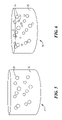
- FIG. 5 is a pictorial view of a portion of the ferromagnetic nanocrystal distribution of FIG. 4 ;
- FIG. 6 is a pictorial view of a portion of an alternative ferromagnetic nanocrystal distribution of FIG. 4 including dopant elements;
- FIG. 7 is an exploded perspective pictorial view of an alternative embodiment of the energy conversion device of FIG. 4 showing a ferromagnetic stackup provided as part of the magnetic dipole module;
- FIG. 8 is an alternative embodiment of the energy conversion system of FIG. 3 including the energy conversion device of FIG. 7 ;
- FIG. 9 is a pictorial perspective view of the magnetic dipole module of FIG. 7 ;
- FIG. 10 is a side pictorial view of the magnetic dipole module of FIG. 9 .
- the present invention is generally directed to a method and device for producing electricity.
- the method of the present invention provides an elegant and efficient process for directly converting energy into electricity.
- an energy conversion device shown generally as reference numeral 10 , includes a magnetic dipole module 11 enclosed by an electrical coil 13 having a plurality of ‘N’ turns or windings.
- the electrical coil 13 is thus immersed in a magnetic field produced by the magnetic dipole module 11 .
- a first turn 15 , a second turn 17 , and a third turn 19 are shown in the diagrammatical representation of FIG. 1 , but it should be understood that the number of turns or windings is much greater than three turns.
- the magnetic dipole module 11 may be generally cylindrical in shape having a module longitudinal axis 21 and comprising a plurality of ferromagnetic nanocrystals 23 distributed within a matrix 25 .
- the ferromagnetic nanocrystals 23 are preferably single-domain particles or smaller, and each ferromagnetic nanocrystal 23 comprises a material having a Curie temperature denoted by T C .
- Each ferromagnetic nanocrystal 23 has an associated nanocrystal magnetic dipole moment 27 generally aligned along the module longitudinal axis 21 .
- each nanocrystal magnetic dipole moment 27 contributes to a module aggregate magnetic field 29 , designated by the vector symbol ⁇ right arrow over (B) ⁇ and defined in accordance with a vector coordinate system 31 .
- the magnetic dipole module 11 may also include a rod-shaped core magnet 33 having a core magnetic dipole moment 35 aligned along, and preferably coincident with, the longitudinal axis 21 . This aligned configuration serves to ensure that the contribution of the core magnetic dipole moment 35 to the strength of the module aggregate magnetic field 29 is optimal.
- the core magnet 33 may comprise a permanent magnet, for example, or an electromagnet to provide a greater core magnetic dipole moment 35 than may be possible with a permanent magnet of similar size.
- a stronger core magnetic dipole moment 35 can, in turn, increase the magnetic strength of the ferromagnetic nanocrystals 23 which can, accordingly, subject the turns or windings of the electrical coil 13 to a greater magnetic flux produced by the magnetic dipole module 11 .
- the ferromagnetic nanocrystals 23 may, under certain conditions, become superparamagnetic.
- the core magnet 33 serves to offset this potential occurrence by maintaining the magnetic moment orientation of the ferromagnetic nanocrystals 23 at temperatures below the Curie temperature until incident radiation decouples the magnetic moments.
- the operation of the energy conversion device 10 follows from Faraday's observation that a transient electrical current can be induced in the electrical coil 13 if the magnetic field ⁇ right arrow over (B) ⁇ is changed as a function of time. This changing magnetic field produces a corresponding change in the magnetic flux across the electrical coil 13 .
- An electromotive force can be induced in an electrical circuit 37 comprising the electrical coil 13 and an external electrical load 39 in response to this change in the magnetic field ⁇ right arrow over (B) ⁇ .
- the electromotive force is proportional to the time rate of change of the magnetic flux linking the electrical coil 13 ,
- the magnitude of the magnetic field ⁇ right arrow over (B) ⁇ can decay and regenerate as a function of radiant energy incident on the energy conversion device 10 .
- the radiant energy may be provided in the form of a radiation beam 41 emitted from a radiation source 43 , as described in greater detail below.
- the matrix 25 is highly transparent to the wavelength ⁇ of the radiation beam 41 such that the radiation source 43 transmits the radiation beam 41 through an enclosure 49 and through the matrix 25 with minimal attenuation to irradiate the ferromagnetic nanocrystals 23 .
- the wavelength ⁇ of the radiation beam 41 is also selected so as to effectively impart thermal energy to irradiated ferromagnetic nanocrystals 23 .
- the enclosure 49 comprises a “soft” magnetic material.
- the ferromagnetic nanocrystals 23 are initially at an ambient temperature T a , where T a is less than the Curie temperature T C of the ferromagnetic nanocrystals 23 .
- T a is less than the Curie temperature T C of the ferromagnetic nanocrystals 23 .
- the energy conversion device 10 is irradiated by the radiation beam 41 for a predetermined amount of time, the ferromagnetic nanocrystals 23 are heated to a temperature of T 1 or greater, where T 1 is greater than the Curie temperature T C .
- the magnetic dipole moments 27 decouple out of alignment with the module longitudinal axis 21 .
- the module magnetic field 29 begins to decay and may decrease to a value approximately that of the core magnetic dipole moment 35 . This results in a decrease in magnetic flux across the electrical coil 13 .
- the irradiation of the magnetic dipole module 11 is reduced or terminated so as to allow heat to flow from the ferromagnetic nanocrystals 23 into the matrix 25 .
- This action can be accomplished by, for example, attenuating the output of the radiation source 43 or by blocking the radiation beam 41 .
- the radiation source comprises a pulsed laser device (not shown) which functions to output a radiation beam 41 , which controllably varies between full power and an attenuated power level.
- the radiation beam can be blocked by closing a shutter 45 , such as an optical Kerr cell or similar device, interposed between the radiation source 43 and the magnetic dipole module 11 .
- a shutter 45 such as an optical Kerr cell or similar device, interposed between the radiation source 43 and the magnetic dipole module 11 .
- Operation of the energy conversion device 10 thus comprises repetitive cycles of alternatingly causing the magnetic flux to decay across the electrical coil 13 and then enabling the magnetic flux to regenerate. These cycles of decay and regeneration are achieved by alternating the steps of: (1) irradiating the ferromagnetic nanocrystals 23 to a temperature of T 1 or higher to cause the magnetic flux to decay, and (2) reducing or terminating the irradiation for a predetermined amount of time to allow the temperatures of the ferromagnetic nanocrystals 23 to fall below T 2 so as to enable the magnetic flux to regenerate across the electrical coil 13 .
- a corresponding electrical current i is produced in the electrical coil 13 with the decay and regeneration of the magnetic flux produced by the ferromagnetic nanocrystals 23 .
- the high output frequency of the electrical current i may be converted to a DC signal, and then to a lower-frequency AC signal, such as a 60 Hz output signal, for example.
- the energy conversion device 10 thus functions to directly convert a portion of the energy in the incident radiation beam 41 into the electrical current i provided to the external electrical load 39 .
- a single domain may be approximately 10 ⁇ 6 to 10 ⁇ 2 cm 3 in size, for example, and may contain 10 15 to 10 21 atoms.
- the small physical sizes of the nanocrystals 23 thus allow the magnetic flux to be cycled at high frequencies.
- single-domain particles having temperatures above the Curie temperature T C can be demagnetized in time intervals as small as one femtosecond. Changing the magnetic field at a high frequency can thus provide a relatively large electrical current even if the magnetic field is relatively small.
- the radiation source 43 can be, for example, a narrowband source such as a laser, or a broadband source such as sunlight.
- the radiation beam 41 can thus comprise a range of frequencies best suited to induce heating of the ferromagnetic nanocrystals 23 .
- the broadband sunlight source may be more practical than a narrowband laser source for providing, or boosting, an external electrical current source.
- the best source to provide electricity e.g., to a subcutaneous cardiac pacemaker or insulin pump, may be a pulsed radio-frequency source.
- an energy conversion device shown generally as reference numeral 50 , comprises a first ferromagnetic suspension chamber 51 at least partially enclosed in a first electrical coil 53 , and a second ferromagnetic suspension chamber 55 at least partially enclosed in a second electrical coil 57 .
- the energy conversion device 50 further includes a disk-shaped core magnet 59 disposed between the first ferromagnetic suspension chamber 51 and the second ferromagnetic suspension chamber 55 .
- the first ferromagnetic suspension chamber 51 includes a first cylindrical shell 61 and a first endcap 63
- the second ferromagnetic suspension chamber 55 includes a second cylindrical shell 65 and a second endcap 67
- the first cylindrical shell 61 , the first endcap 63 , the second cylindrical shell 65 , and the second endcap 67 can be fabricated from: (1) aluminum; (2) a nonmagnetic material or soft metal such does not hold a magnetic force when not in a magnetic field; or (3) a “soft” magnetic material.
- the first ferromagnetic suspension chamber 51 houses a first ferromagnetic suspension 71 comprising a distribution of the aligned ferromagnetic nanocrystals 23 in the matrix 25 .
- the second ferromagnetic suspension chamber 55 also houses a second ferromagnetic suspension 73 comprising a plurality of the ferromagnetic nanocrystals 23 disposed in the matrix 25 .
- Radiant energy is provided to the energy conversion device 50 by a radiation source 81 , such as a pulsed laser source.
- the radiation source 81 provides pulsed radiation (not shown) to the first ferromagnetic suspension 71 via a first optical fiber 83 , and pulsed radiation to the second ferromagnetic suspension 73 via a second optical fiber 85 .
- the energy conversion device 50 , the radiation source 81 , the first optical fiber 83 , and second optical fiber 83 form an energy conversion system 20 .
- the radiation pulses may be provided to the two ferromagnetic suspensions 71 and 73 either simultaneously or alternately.
- the nanocrystals 23 comprise nickel having a Curie temperature of about 627° K., and the matrix 25 comprises aluminum oxide.
- the nanocrystals 23 comprise iron having a Curie temperature of about 1043° K.
- the nanocrystals 23 may be formed from: (1) “hard” ferromagnetic crystals comprising metal ions such as cobalt, neodymium, or gadolinium; (2) ferrite crystals comprising metal ions such as cobalt, neodymium, or gadolinium; or (3) ferrites such as yttrium-iron-garnet.
- a ferrite crystal may produce a weaker magnetic field than when utilizing a nanocrystal, but the frequency of operation may be greater than that for nonocrystals.
- a doped ferromagnetic suspension 75 comprising a distribution of nanocrystals 23 in the matrix 25 .
- the doped ferromagnetic suspension 75 further comprises a distribution of dopant particles 77 comprised of a material such as titanium, copper, yttrium, or other such transition metal.
- the dopant particles 77 may serve to scatter the radiation from the radiation source 81 throughout the first ferromagnetic suspension chamber 51 or the second ferromagnetic suspension chamber 55 .
- the dopant particles would also serve to absorb heat from the nanocrystals 23 .
- the dopant particles 77 comprise a material such as Ti:Sapphire-titanium-doped sapphire (Ti 3+ :Al 2 O 3 ).
- an energy conversion device shown generally as reference numeral 90 , comprises a first layered ferromagnetic chamber 91 at least partially enclosed in the first electrical coil 53 , and a second layered ferromagnetic chamber 93 at least partially enclosed in the second electrical coil 57 .
- the energy conversion device 90 may include the disk-shaped core magnet 59 disposed between the first layered ferromagnetic chamber 91 and the second layered ferromagnetic chamber 93 .
- the first layered ferromagnetic chamber 91 includes the first cylindrical shell 61 , a first layered ferromagnet 95 , and the first endcap 63 .
- the second layered ferromagnetic chamber 93 includes the second cylindrical shell 65 , a second layered ferromagnet 97 , and the second endcap 67 .
- the energy conversion device 90 can be used with the radiation source 81 , the first optical fiber 83 , and the second optical fiber 85 to form an energy conversion system 100 , shown in FIG. 8 .
- the energy conversion system 100 may comprise the first layered ferromagnetic chamber 91 , the first electrical coil 53 , the first optical fiber 83 , and the radiation source 81 .
- the first layered ferromagnet 95 comprises a plurality of “soft” ferromagnetic annular disks 101 alternately stacked with a plurality of inner Ti:Sapphire annular disks 103 .
- An outer Ti:Sapphire annular disk 105 is provided at both ends of the first layered ferromagnet 95 .
- the outer Ti:Sapphire annular disk 105 may also include a coating 113 which is highly reflective to the wavelength ⁇ of the radiation beam 41 .
- the configuration of the second layered ferromagnet 97 is similar to that of the first layered ferromagnet 95 .
- FIG. 9 shows a stack of four soft ferromagnetic annular disks 101 and three inner Ti:Sapphire annular disks 103 but it should be understood that fewer or more soft ferromagnetic annular disks 101 and Ti:Sapphire annular disks 103 can be used in the first layered ferromagnet 95 and in the second layered ferromagnet 97 .
- the first layered ferromagnet 95 also includes a cylindrical Ti:Sapphire core 107 extending through the inside of the stack comprising the soft ferromagnetic annular disks 101 , the inner Ti:Sapphire annular disks 103 , and the outer Ti:Sapphire annular disks 105 .
- the Ti:Sapphire core 107 is disposed along a layered ferromagnet axis 109 of the first layered ferromagnet 95 .
- Each of the soft ferromagnetic annular disks 101 includes a ferromagnetic nanocrystal coating 111 on a first disk face 115 and on a second disk face 117 , as best seen in FIG. 10 .
- Each soft ferromagnetic annular disk 101 also includes a central opening 119
- each inner Ti:Sapphire annular disks 103 includes a central opening 121
- each outer Ti:Sapphire annular disk 105 includes a central opening 123 .
- Each of the central openings 119 , the central openings 121 , and the central openings 123 is preferably sized to allow insertion of the Ti:Sapphire core 107 .
- This configuration provides for the placement of the cylindrical Ti:Sapphire core 107 into the stack comprising the soft ferromagnetic annular disks 101 , the inner Ti:Sapphire annular disks 103 , and the outer Ti:Sapphire annular disks 105 as shown.
- the ferromagnetic nanocrystal coating 111 comprises a layer of the matrix 25 having embedded therein a plurality of “hard” ferromagnetic nanocrystals 23 (not shown) with respective nanocrystal magnetic dipole moments (not shown) aligned with the layered ferromagnet axis 109 .
- the soft ferromagnetic annular disks 101 comprise a magnetic material having a Curie temperature T Csoft where T Csoft >T C , the Curie temperature of the ferromagnetic nanocrystals 23 .
- the ferromagnetic nanocrystals 23 may comprise nickel or iron, as described above, or may comprise iron-nickel-titanium alloy particles of sufficiently large size that the ferromagnetic nanocrystals 23 are not superparamagnetic.
- the magnetic dipole moments 27 produce the module aggregate magnetic field 29 , shown in FIG. 9 .
- Operation of the energy conversion system 100 includes irradiating the first layered ferromagnet 95 and the second layered ferromagnet 97 with the radiation beam 41 , as described above for the energy conversion system 20 .
- the radiation beam 41 is transmitted to the first layered ferromagnet 95 , for example, via the first optical fiber 83 . From the first optical fiber 83 , the radiation beam 41 is directed into the Ti:Sapphire core 107 , as indicated by arrow 114 .
- the radiation beam 41 is internally scattered into the plurality of inner Ti:Sapphire annular disks 103 , such as indicated by arrows 116 and 118 , and into the two outer Ti:Sapphire annular disks 105 .
- the scattered radiation beam 41 irradiates the ferromagnetic nanocrystals 23 embedded in the plurality of ferromagnetic nanocrystal coatings 111 on the soft ferromagnetic disks 101 .
- the nanocrystal magnetic dipole moments 27 are uncoupled by the incident radiation and begin to decay. This action causes the soft ferromagnetic annular disks 101 to demagnetize, causes the module aggregate magnetic field 29 to collapse, and results in the generation of an electrical current in the first electrical coil 53 as described in greater detail above.
- discs comprising yttrium aluminum garnet are used in place of the Ti:Sapphire annular disks 103 and 105 , and a core comprising yttrium aluminum garnet is used in place of the Ti:Sapphire core 107 .
- the yttrium aluminum garnet discs comprise coatings of yttrium-iron-garnet (YIG) nanocrystal particles.
Abstract
A method and apparatus are provided for converting electromagnetic radiation directly into electricity. The method aligns a plurality of ferromagnetic nanocrystals to produce an aggregate magnetic field; utilizes an electrical coil in the aggregate magnetic field; and alternately directs and removes radiant energy from the ferromagnetic nanocrystals such that the aggregate magnetic field decays and regenerates to produce a current in the electrical coil. The apparatus includes either a distribution or a stackup of ferro-magnetic nanocrystals and an electrical coil, the combination of the nanocrystals and the electrical coil operating with energy derived from the source of radiant energy.
Description
This application is a continuation of application Ser. No. 10/784,086 filed on Feb. 20, 2004 now U.S. Pat. No. 7,098,547 issued on Aug. 29, 2006.
1. Field of the Invention
The present invention relates generally to the direct conversion of radiant energy into electricity, and more particularly, to a method and apparatus for producing electricity by causing a magnetic field to alternatingly decay and regenerate.
2. Description of the Prior Art
Historically, electricity has been produced by using a generator device to move an electrical coil and a magnetic field relative to one another. Such methods require mechanical moving parts which can wear out or break down and create an interruption in providing electrical power to components.
Various methods have been proposed to directly convert an energy source directly into electricity. U.S. Pat. No. 5,714,829 issued to Gurusprasad, for example, discloses a magnetic mechanical heat engine for converting heat into electricity using electromotive force induced by demagnetization. The heat engine utilizes a magnetic medium which is magnetized by means of a magnetic field produced by an external electrical coil. However, operation of the apparatus disclosed in Gurusprasad '829 requires that the magnetic medium be brought into and out of thermal contact with a heat source, which thus necessitates moving parts and reduces the efficiency of the apparatus.
What is needed is an apparatus for efficiently converting energy directly into electricity.
The present invention provides a method and an energy conversion device for efficiently converting radiant energy directly into electricity.
In one general aspect of the present invention, a first embodiment comprises a distribution of ferro-magnetic nanocrystals and an electrical coil, the combination operating with energy directed from a radiation source.
In another general aspect of the present invention, a second embodiment comprises two distributions of ferromagnetic nanocrystals, a pair of electrical coils enclosing the ferromagnetic nanocrystals, and a controllable radiation source.
In yet another general aspect of the present invention, a third embodiment comprises a controllable radiation source, a plurality of transparent annular disks alternatingly stacked with a plurality of soft magnetic disks coated with ferromagnetic nanocrystals embedded in a matrix layer, a transparent cylindrical core, and an electrical coil enclosing the stacked annular disks and cylindrical core.
In a further general aspect of the present invention, a method is provided for converting energy from a radiant source into electricity. Initially, a plurality of ferromagnetic nanocrystals are aligned so as to produce an aggregate magnetic field; an electrical conductor is placed into the aggregate magnetic field; and radiant energy is directed onto the plurality of ferromagnetic nanocrystals such that the aggregate magnetic field begins to decay. The radiant energy is then attenuated, allowing the aggregate magnetic field to regenerate, and the process is repeated inducing electric current in the electrical conductor in response to the changing magnetic field.
These and other aspects, features, and advantages of the present invention will become more readily apparent from the attached drawings and the detailed description of the preferred embodiments, which follow.
The preferred embodiments of the invention will hereinafter be described in conjunction with the appended drawings provided to illustrate and not to limit the invention, where like designations denote like elements, and in which:
Shown throughout the figures, the present invention is generally directed to a method and device for producing electricity. In comparison to other methods known in the art, the method of the present invention provides an elegant and efficient process for directly converting energy into electricity.
Referring initially to FIGS. 1-2 , an energy conversion device, shown generally as reference numeral 10, includes a magnetic dipole module 11 enclosed by an electrical coil 13 having a plurality of ‘N’ turns or windings. The electrical coil 13 is thus immersed in a magnetic field produced by the magnetic dipole module 11. For clarity of illustration, only a first turn 15, a second turn 17, and a third turn 19 are shown in the diagrammatical representation of FIG. 1 , but it should be understood that the number of turns or windings is much greater than three turns.
The magnetic dipole module 11 may be generally cylindrical in shape having a module longitudinal axis 21 and comprising a plurality of ferromagnetic nanocrystals 23 distributed within a matrix 25. The ferromagnetic nanocrystals 23 are preferably single-domain particles or smaller, and each ferromagnetic nanocrystal 23 comprises a material having a Curie temperature denoted by TC.
Each ferromagnetic nanocrystal 23 has an associated nanocrystal magnetic dipole moment 27 generally aligned along the module longitudinal axis 21. In this aligned configuration, each nanocrystal magnetic dipole moment 27 contributes to a module aggregate magnetic field 29, designated by the vector symbol {right arrow over (B)} and defined in accordance with a vector coordinate system 31.
The magnetic dipole module 11 may also include a rod-shaped core magnet 33 having a core magnetic dipole moment 35 aligned along, and preferably coincident with, the longitudinal axis 21. This aligned configuration serves to ensure that the contribution of the core magnetic dipole moment 35 to the strength of the module aggregate magnetic field 29 is optimal.
The core magnet 33 may comprise a permanent magnet, for example, or an electromagnet to provide a greater core magnetic dipole moment 35 than may be possible with a permanent magnet of similar size. A stronger core magnetic dipole moment 35 can, in turn, increase the magnetic strength of the ferromagnetic nanocrystals 23 which can, accordingly, subject the turns or windings of the electrical coil 13 to a greater magnetic flux produced by the magnetic dipole module 11.
Because of extremely small physical size, the ferromagnetic nanocrystals 23 may, under certain conditions, become superparamagnetic. The core magnet 33 serves to offset this potential occurrence by maintaining the magnetic moment orientation of the ferromagnetic nanocrystals 23 at temperatures below the Curie temperature until incident radiation decouples the magnetic moments.
The operation of the energy conversion device 10 follows from Faraday's observation that a transient electrical current can be induced in the electrical coil 13 if the magnetic field {right arrow over (B)} is changed as a function of time. This changing magnetic field produces a corresponding change in the magnetic flux across the electrical coil 13. An electromotive force can be induced in an electrical circuit 37 comprising the electrical coil 13 and an external electrical load 39 in response to this change in the magnetic field {right arrow over (B)}. In accordance with Faraday's Law, the electromotive force is proportional to the time rate of change of the magnetic flux linking the electrical coil 13,
where
-
- E is the electromotive force around the
electrical coil 13; - k is a constant of proportionality dependent on the choice of units for the electric and magnetic field quantities; and
- F is the magnetic flux linking the
electrical circuit 37 which includesturns
The negative value of k indicates that the induced current (and accompanying magnetic flux) is in such a direction as to oppose the change of flux through the windings of the electrical coil 13 (exemplified by theturns electrical coil 13.
- E is the electromotive force around the
In accordance with the present invention, the magnitude of the magnetic field {right arrow over (B)} can decay and regenerate as a function of radiant energy incident on the energy conversion device 10. The radiant energy may be provided in the form of a radiation beam 41 emitted from a radiation source 43, as described in greater detail below.
The matrix 25 is highly transparent to the wavelength λ of the radiation beam 41 such that the radiation source 43 transmits the radiation beam 41 through an enclosure 49 and through the matrix 25 with minimal attenuation to irradiate the ferromagnetic nanocrystals 23. Preferably, the wavelength λ of the radiation beam 41 is also selected so as to effectively impart thermal energy to irradiated ferromagnetic nanocrystals 23. In an alternative embodiment, the enclosure 49 comprises a “soft” magnetic material.
At the start of operation, that is, before the radiation source 43 is powered to direct the radiation beam onto the magnetic dipole module 11, the ferromagnetic nanocrystals 23 are initially at an ambient temperature Ta, where Ta is less than the Curie temperature TC of the ferromagnetic nanocrystals 23. When the energy conversion device 10 is irradiated by the radiation beam 41 for a predetermined amount of time, the ferromagnetic nanocrystals 23 are heated to a temperature of T1 or greater, where T1 is greater than the Curie temperature TC.
As the respective temperatures of the ferromagnetic nanocrystals 23 rise above the Curie temperature TC, the magnetic dipole moments 27 decouple out of alignment with the module longitudinal axis 21. The module magnetic field 29 begins to decay and may decrease to a value approximately that of the core magnetic dipole moment 35. This results in a decrease in magnetic flux across the electrical coil 13.
After a predetermined period of time, the irradiation of the magnetic dipole module 11 is reduced or terminated so as to allow heat to flow from the ferromagnetic nanocrystals 23 into the matrix 25. This action can be accomplished by, for example, attenuating the output of the radiation source 43 or by blocking the radiation beam 41. In one embodiment, the radiation source comprises a pulsed laser device (not shown) which functions to output a radiation beam 41, which controllably varies between full power and an attenuated power level.
In an alternative embodiment, the radiation beam can be blocked by closing a shutter 45, such as an optical Kerr cell or similar device, interposed between the radiation source 43 and the magnetic dipole module 11. As the nanocrystals 23 lose heat to the relatively cooler matrix 25, the temperatures of the nanocrystals 23 drop to a value of T2 or lower, where T2 lies below the Curie temperature. That is, T2<TC<T1. This drop in temperature allows the magnetic flux to regenerate and to reappear across the electrical coil 13.
Operation of the energy conversion device 10 thus comprises repetitive cycles of alternatingly causing the magnetic flux to decay across the electrical coil 13 and then enabling the magnetic flux to regenerate. These cycles of decay and regeneration are achieved by alternating the steps of: (1) irradiating the ferromagnetic nanocrystals 23 to a temperature of T1 or higher to cause the magnetic flux to decay, and (2) reducing or terminating the irradiation for a predetermined amount of time to allow the temperatures of the ferromagnetic nanocrystals 23 to fall below T2 so as to enable the magnetic flux to regenerate across the electrical coil 13.
In accordance with Faraday's Law, a corresponding electrical current i, indicated by an arrow 47, is produced in the electrical coil 13 with the decay and regeneration of the magnetic flux produced by the ferromagnetic nanocrystals 23. The high output frequency of the electrical current i, may be converted to a DC signal, and then to a lower-frequency AC signal, such as a 60 Hz output signal, for example. The energy conversion device 10 thus functions to directly convert a portion of the energy in the incident radiation beam 41 into the electrical current i provided to the external electrical load 39.
As understood by one skilled in the relevant art, a single domain may be approximately 10−6 to 10−2 cm3 in size, for example, and may contain 1015 to 1021 atoms. The small physical sizes of the nanocrystals 23 thus allow the magnetic flux to be cycled at high frequencies. For example, single-domain particles having temperatures above the Curie temperature TC can be demagnetized in time intervals as small as one femtosecond. Changing the magnetic field at a high frequency can thus provide a relatively large electrical current even if the magnetic field is relatively small.
The radiation source 43 can be, for example, a narrowband source such as a laser, or a broadband source such as sunlight. The radiation beam 41 can thus comprise a range of frequencies best suited to induce heating of the ferromagnetic nanocrystals 23. As can be appreciated by one skilled in the art, the broadband sunlight source may be more practical than a narrowband laser source for providing, or boosting, an external electrical current source. In other applications, the best source to provide electricity, e.g., to a subcutaneous cardiac pacemaker or insulin pump, may be a pulsed radio-frequency source.
Referring now to FIGS. 3-4 , an energy conversion device, shown generally as reference numeral 50, comprises a first ferromagnetic suspension chamber 51 at least partially enclosed in a first electrical coil 53, and a second ferromagnetic suspension chamber 55 at least partially enclosed in a second electrical coil 57. The energy conversion device 50 further includes a disk-shaped core magnet 59 disposed between the first ferromagnetic suspension chamber 51 and the second ferromagnetic suspension chamber 55.
The first ferromagnetic suspension chamber 51 includes a first cylindrical shell 61 and a first endcap 63, and the second ferromagnetic suspension chamber 55 includes a second cylindrical shell 65 and a second endcap 67. The first cylindrical shell 61, the first endcap 63, the second cylindrical shell 65, and the second endcap 67 can be fabricated from: (1) aluminum; (2) a nonmagnetic material or soft metal such does not hold a magnetic force when not in a magnetic field; or (3) a “soft” magnetic material. The first ferromagnetic suspension chamber 51 houses a first ferromagnetic suspension 71 comprising a distribution of the aligned ferromagnetic nanocrystals 23 in the matrix 25. Likewise, the second ferromagnetic suspension chamber 55 also houses a second ferromagnetic suspension 73 comprising a plurality of the ferromagnetic nanocrystals 23 disposed in the matrix 25.
Radiant energy is provided to the energy conversion device 50 by a radiation source 81, such as a pulsed laser source. When operating in accordance with the present invention, the radiation source 81 provides pulsed radiation (not shown) to the first ferromagnetic suspension 71 via a first optical fiber 83, and pulsed radiation to the second ferromagnetic suspension 73 via a second optical fiber 85. The energy conversion device 50, the radiation source 81, the first optical fiber 83, and second optical fiber 83 form an energy conversion system 20. The radiation pulses may be provided to the two ferromagnetic suspensions 71 and 73 either simultaneously or alternately.
Referring now to FIG. 5 , in which the first ferromagnetic suspension 71 is shown in greater detail, the nanocrystals 23 comprise nickel having a Curie temperature of about 627° K., and the matrix 25 comprises aluminum oxide. In an alternative embodiment, the nanocrystals 23 comprise iron having a Curie temperature of about 1043° K. In other alternative embodiments, the nanocrystals 23 may be formed from: (1) “hard” ferromagnetic crystals comprising metal ions such as cobalt, neodymium, or gadolinium; (2) ferrite crystals comprising metal ions such as cobalt, neodymium, or gadolinium; or (3) ferrites such as yttrium-iron-garnet. When utilized in the first ferromagnetic suspension 71, a ferrite crystal may produce a weaker magnetic field than when utilizing a nanocrystal, but the frequency of operation may be greater than that for nonocrystals.
Referring now to FIG. 6 , a doped ferromagnetic suspension 75 is shown comprising a distribution of nanocrystals 23 in the matrix 25. The doped ferromagnetic suspension 75 further comprises a distribution of dopant particles 77 comprised of a material such as titanium, copper, yttrium, or other such transition metal. The dopant particles 77 may serve to scatter the radiation from the radiation source 81 throughout the first ferromagnetic suspension chamber 51 or the second ferromagnetic suspension chamber 55. In addition, as titanium has a relatively high thermal conductivity, the dopant particles would also serve to absorb heat from the nanocrystals 23. In yet another alternative embodiment, the dopant particles 77 comprise a material such as Ti:Sapphire-titanium-doped sapphire (Ti3+:Al2O3).
Referring now to FIG. 7 , an energy conversion device, shown generally as reference numeral 90, comprises a first layered ferromagnetic chamber 91 at least partially enclosed in the first electrical coil 53, and a second layered ferromagnetic chamber 93 at least partially enclosed in the second electrical coil 57. In an alternative embodiment, the energy conversion device 90 may include the disk-shaped core magnet 59 disposed between the first layered ferromagnetic chamber 91 and the second layered ferromagnetic chamber 93.
The first layered ferromagnetic chamber 91 includes the first cylindrical shell 61, a first layered ferromagnet 95, and the first endcap 63. The second layered ferromagnetic chamber 93 includes the second cylindrical shell 65, a second layered ferromagnet 97, and the second endcap 67. The energy conversion device 90 can be used with the radiation source 81, the first optical fiber 83, and the second optical fiber 85 to form an energy conversion system 100, shown in FIG. 8 . In an alternative embodiment, the energy conversion system 100 may comprise the first layered ferromagnetic chamber 91, the first electrical coil 53, the first optical fiber 83, and the radiation source 81.
Referring now to FIGS. 9-10 , the first layered ferromagnet 95 comprises a plurality of “soft” ferromagnetic annular disks 101 alternately stacked with a plurality of inner Ti:Sapphire annular disks 103. An outer Ti:Sapphire annular disk 105 is provided at both ends of the first layered ferromagnet 95. The outer Ti:Sapphire annular disk 105 may also include a coating 113 which is highly reflective to the wavelength λ of the radiation beam 41. The configuration of the second layered ferromagnet 97 is similar to that of the first layered ferromagnet 95.
For clarity of illustration, the perspective view of FIG. 9 shows a stack of four soft ferromagnetic annular disks 101 and three inner Ti:Sapphire annular disks 103 but it should be understood that fewer or more soft ferromagnetic annular disks 101 and Ti:Sapphire annular disks 103 can be used in the first layered ferromagnet 95 and in the second layered ferromagnet 97.
The first layered ferromagnet 95 also includes a cylindrical Ti:Sapphire core 107 extending through the inside of the stack comprising the soft ferromagnetic annular disks 101, the inner Ti:Sapphire annular disks 103, and the outer Ti:Sapphire annular disks 105. Preferably, the Ti:Sapphire core 107 is disposed along a layered ferromagnet axis 109 of the first layered ferromagnet 95.
Each of the soft ferromagnetic annular disks 101 includes a ferromagnetic nanocrystal coating 111 on a first disk face 115 and on a second disk face 117, as best seen in FIG. 10 . Each soft ferromagnetic annular disk 101 also includes a central opening 119, each inner Ti:Sapphire annular disks 103 includes a central opening 121, and each outer Ti:Sapphire annular disk 105 includes a central opening 123. Each of the central openings 119, the central openings 121, and the central openings 123 is preferably sized to allow insertion of the Ti:Sapphire core 107. This configuration provides for the placement of the cylindrical Ti:Sapphire core 107 into the stack comprising the soft ferromagnetic annular disks 101, the inner Ti:Sapphire annular disks 103, and the outer Ti:Sapphire annular disks 105 as shown.
The ferromagnetic nanocrystal coating 111 comprises a layer of the matrix 25 having embedded therein a plurality of “hard” ferromagnetic nanocrystals 23 (not shown) with respective nanocrystal magnetic dipole moments (not shown) aligned with the layered ferromagnet axis 109. The soft ferromagnetic annular disks 101 comprise a magnetic material having a Curie temperature TCsoft where TCsoft>TC, the Curie temperature of the ferromagnetic nanocrystals 23. The ferromagnetic nanocrystals 23 may comprise nickel or iron, as described above, or may comprise iron-nickel-titanium alloy particles of sufficiently large size that the ferromagnetic nanocrystals 23 are not superparamagnetic. The magnetic dipole moments 27 produce the module aggregate magnetic field 29, shown in FIG. 9 .
Operation of the energy conversion system 100 includes irradiating the first layered ferromagnet 95 and the second layered ferromagnet 97 with the radiation beam 41, as described above for the energy conversion system 20. The radiation beam 41 is transmitted to the first layered ferromagnet 95, for example, via the first optical fiber 83. From the first optical fiber 83, the radiation beam 41 is directed into the Ti:Sapphire core 107, as indicated by arrow 114. As the Ti:Sapphire core 107 is transparent to the radiation beam 41, the radiation beam 41 is internally scattered into the plurality of inner Ti:Sapphire annular disks 103, such as indicated by arrows 116 and 118, and into the two outer Ti:Sapphire annular disks 105.
The scattered radiation beam 41 irradiates the ferromagnetic nanocrystals 23 embedded in the plurality of ferromagnetic nanocrystal coatings 111 on the soft ferromagnetic disks 101. The nanocrystal magnetic dipole moments 27 are uncoupled by the incident radiation and begin to decay. This action causes the soft ferromagnetic annular disks 101 to demagnetize, causes the module aggregate magnetic field 29 to collapse, and results in the generation of an electrical current in the first electrical coil 53 as described in greater detail above.
In an alternative embodiment, discs comprising yttrium aluminum garnet (YAG) are used in place of the Ti:Sapphire annular disks 103 and 105, and a core comprising yttrium aluminum garnet is used in place of the Ti:Sapphire core 107. Additionally, the yttrium aluminum garnet discs comprise coatings of yttrium-iron-garnet (YIG) nanocrystal particles.
Since many modifications, variations, and changes in detail can be made to the described preferred embodiments of the invention, it is intended that all matters in the foregoing description and shown in the accompanying drawings be interpreted as illustrative and not in a limiting sense. Thus, the scope of the invention should be determined by the appended claims and their legal equivalence.
Claims (3)
1. A system for generating electricity, said system comprising:
a magnetic dipole module having a plurality of single-domain magnetic particles disposed in a matrix; and
a source of radiant energy for irradiating said magnetic dipole module, wherein said source of radiant energy comprises a laser;
an electrical coil enclosing at least a portion of said magnetic dipole module.
2. A system as recited in claim 1 further comprising a shutter disposed between said source of radiant energy and said magnetic dipole module.
3. A system as recited in claim 1 further comprising an optical fiber having a first end attached to said source of radiant energy and a second end attached to said magnetic dipole module.
Priority Applications (1)
| Application Number | Priority Date | Filing Date | Title |
|---|---|---|---|
| US11/483,055 US7679205B1 (en) | 2004-02-20 | 2006-07-07 | Method and apparatus for converting energy to electricity |
Applications Claiming Priority (2)
| Application Number | Priority Date | Filing Date | Title |
|---|---|---|---|
| US10/784,086 US7098547B1 (en) | 2004-02-20 | 2004-02-20 | Method and apparatus for converting energy to electricity |
| US11/483,055 US7679205B1 (en) | 2004-02-20 | 2006-07-07 | Method and apparatus for converting energy to electricity |
Related Parent Applications (1)
| Application Number | Title | Priority Date | Filing Date |
|---|---|---|---|
| US10/784,086 Continuation US7098547B1 (en) | 2004-02-20 | 2004-02-20 | Method and apparatus for converting energy to electricity |
Publications (1)
| Publication Number | Publication Date |
|---|---|
| US7679205B1 true US7679205B1 (en) | 2010-03-16 |
Family
ID=36915554
Family Applications (2)
| Application Number | Title | Priority Date | Filing Date |
|---|---|---|---|
| US10/784,086 Expired - Fee Related US7098547B1 (en) | 2004-02-20 | 2004-02-20 | Method and apparatus for converting energy to electricity |
| US11/483,055 Expired - Fee Related US7679205B1 (en) | 2004-02-20 | 2006-07-07 | Method and apparatus for converting energy to electricity |
Family Applications Before (1)
| Application Number | Title | Priority Date | Filing Date |
|---|---|---|---|
| US10/784,086 Expired - Fee Related US7098547B1 (en) | 2004-02-20 | 2004-02-20 | Method and apparatus for converting energy to electricity |
Country Status (1)
| Country | Link |
|---|---|
| US (2) | US7098547B1 (en) |
Cited By (12)
| Publication number | Priority date | Publication date | Assignee | Title |
|---|---|---|---|---|
| US20110121145A1 (en) * | 2009-11-24 | 2011-05-26 | Miodrag Mihajlovic | Modular support assembly |
| US20120211995A1 (en) * | 2011-02-22 | 2012-08-23 | Zodiac Pool Systems, Inc. | Hoses principally for automatic swimming pool cleaners |
| CN103825535A (en) * | 2014-03-03 | 2014-05-28 | 河南师范大学 | Optical energy and kinetic energy complementary mobile power supply |
| US20170092409A1 (en) * | 2015-09-30 | 2017-03-30 | Apple Inc. | Preferentially Magnetically Oriented Ferrites for Improved Power Transfer |
| US10044232B2 (en) | 2014-04-04 | 2018-08-07 | Apple Inc. | Inductive power transfer using acoustic or haptic devices |
| US10135303B2 (en) | 2014-05-19 | 2018-11-20 | Apple Inc. | Operating a wireless power transfer system at multiple frequencies |
| US10158244B2 (en) | 2015-09-24 | 2018-12-18 | Apple Inc. | Configurable wireless transmitter device |
| US10477741B1 (en) | 2015-09-29 | 2019-11-12 | Apple Inc. | Communication enabled EMF shield enclosures |
| US10594160B2 (en) | 2017-01-11 | 2020-03-17 | Apple Inc. | Noise mitigation in wireless power systems |
| US10651685B1 (en) | 2015-09-30 | 2020-05-12 | Apple Inc. | Selective activation of a wireless transmitter device |
| US10734840B2 (en) | 2016-08-26 | 2020-08-04 | Apple Inc. | Shared power converter for a wireless transmitter device |
| US10790699B2 (en) | 2015-09-24 | 2020-09-29 | Apple Inc. | Configurable wireless transmitter device |
Families Citing this family (5)
| Publication number | Priority date | Publication date | Assignee | Title |
|---|---|---|---|---|
| WO2008116792A1 (en) * | 2007-03-28 | 2008-10-02 | Abb Research Ltd | Thermomagnetic generator device and energy converting method |
| DE202010010593U1 (en) * | 2010-07-23 | 2011-10-24 | Different Power Ideas Gmbh | Machine for converting electrical and / or magnetic energy into mechanical energy or for converting mechanical energy into electrical energy |
| US20150001989A1 (en) * | 2011-08-31 | 2015-01-01 | Daihatsu Motor Co., Ltd. | Power-generating system |
| US20140217852A1 (en) * | 2011-08-31 | 2014-08-07 | Daihatsu Motor Co., Ltd. | Power-generating system |
| US10468180B2 (en) * | 2017-08-18 | 2019-11-05 | Rosemount Aerospace Inc. | Electromagnetic energy harvester for aircraft applications |
Citations (13)
| Publication number | Priority date | Publication date | Assignee | Title |
|---|---|---|---|---|
| US476983A (en) * | 1892-06-14 | Pyromagnetic generator | ||
| US481999A (en) * | 1892-09-06 | beelinee | ||
| US2619603A (en) * | 1949-05-31 | 1952-11-25 | Technical Assets Inc | Thermomagnetic generator and refrigerator |
| US3274405A (en) * | 1964-03-17 | 1966-09-20 | Du Pont | Energy conversion devices |
| US3899696A (en) * | 1974-03-27 | 1975-08-12 | Nasa | Electric power generation system directly from laser power |
| US4323808A (en) * | 1979-04-24 | 1982-04-06 | Davis Edwin D | Laser excited thermionic electric converter |
| EP0308611A1 (en) * | 1987-09-25 | 1989-03-29 | Hans-Wilhelm Stephan | Magnetocaloric, monostable and bistable generator for producing electrical power and for producing cold |
| JPH09274997A (en) * | 1996-02-09 | 1997-10-21 | Nippon Paint Co Ltd | Compact type atmospheric pressure plasma generating device and surface treatment device using the device |
| US20020160190A1 (en) * | 1998-11-06 | 2002-10-31 | Tapesh Yadav | Nanotechnology for magnetic components |
| US6660566B2 (en) * | 1999-03-30 | 2003-12-09 | Polymatech Co., Ltd. | Heat conductive molded body and manufacturing method thereof and semiconductor device |
| US6700472B2 (en) * | 2001-12-11 | 2004-03-02 | Intersil Americas Inc. | Magnetic thin film inductors |
| US6725668B1 (en) * | 1999-04-19 | 2004-04-27 | Remi Oseri Cornwall | Thermodynamic cycles and method for generating electricity |
| US6849926B2 (en) * | 2000-04-24 | 2005-02-01 | Pohang University Of Science And Technology Foundation | Low dielectric constant composite material containing nano magnetic particles, and optical and semiconductor devices using the low dielectric constant composite material |
-
2004
- 2004-02-20 US US10/784,086 patent/US7098547B1/en not_active Expired - Fee Related
-
2006
- 2006-07-07 US US11/483,055 patent/US7679205B1/en not_active Expired - Fee Related
Patent Citations (13)
| Publication number | Priority date | Publication date | Assignee | Title |
|---|---|---|---|---|
| US476983A (en) * | 1892-06-14 | Pyromagnetic generator | ||
| US481999A (en) * | 1892-09-06 | beelinee | ||
| US2619603A (en) * | 1949-05-31 | 1952-11-25 | Technical Assets Inc | Thermomagnetic generator and refrigerator |
| US3274405A (en) * | 1964-03-17 | 1966-09-20 | Du Pont | Energy conversion devices |
| US3899696A (en) * | 1974-03-27 | 1975-08-12 | Nasa | Electric power generation system directly from laser power |
| US4323808A (en) * | 1979-04-24 | 1982-04-06 | Davis Edwin D | Laser excited thermionic electric converter |
| EP0308611A1 (en) * | 1987-09-25 | 1989-03-29 | Hans-Wilhelm Stephan | Magnetocaloric, monostable and bistable generator for producing electrical power and for producing cold |
| JPH09274997A (en) * | 1996-02-09 | 1997-10-21 | Nippon Paint Co Ltd | Compact type atmospheric pressure plasma generating device and surface treatment device using the device |
| US20020160190A1 (en) * | 1998-11-06 | 2002-10-31 | Tapesh Yadav | Nanotechnology for magnetic components |
| US6660566B2 (en) * | 1999-03-30 | 2003-12-09 | Polymatech Co., Ltd. | Heat conductive molded body and manufacturing method thereof and semiconductor device |
| US6725668B1 (en) * | 1999-04-19 | 2004-04-27 | Remi Oseri Cornwall | Thermodynamic cycles and method for generating electricity |
| US6849926B2 (en) * | 2000-04-24 | 2005-02-01 | Pohang University Of Science And Technology Foundation | Low dielectric constant composite material containing nano magnetic particles, and optical and semiconductor devices using the low dielectric constant composite material |
| US6700472B2 (en) * | 2001-12-11 | 2004-03-02 | Intersil Americas Inc. | Magnetic thin film inductors |
Cited By (15)
| Publication number | Priority date | Publication date | Assignee | Title |
|---|---|---|---|---|
| US8973881B2 (en) * | 2009-11-24 | 2015-03-10 | Miodrag Mihajlovic | Modular support assembly |
| US20110121145A1 (en) * | 2009-11-24 | 2011-05-26 | Miodrag Mihajlovic | Modular support assembly |
| US20120211995A1 (en) * | 2011-02-22 | 2012-08-23 | Zodiac Pool Systems, Inc. | Hoses principally for automatic swimming pool cleaners |
| US9581275B2 (en) * | 2011-02-22 | 2017-02-28 | Zodiac Pool Systems, Inc. | Hoses principally for automatic swimming pool cleaners |
| CN103825535A (en) * | 2014-03-03 | 2014-05-28 | 河南师范大学 | Optical energy and kinetic energy complementary mobile power supply |
| CN103825535B (en) * | 2014-03-03 | 2016-02-03 | 河南师范大学 | The complementary portable power source of a kind of luminous energy kinetic energy |
| US10044232B2 (en) | 2014-04-04 | 2018-08-07 | Apple Inc. | Inductive power transfer using acoustic or haptic devices |
| US10135303B2 (en) | 2014-05-19 | 2018-11-20 | Apple Inc. | Operating a wireless power transfer system at multiple frequencies |
| US10158244B2 (en) | 2015-09-24 | 2018-12-18 | Apple Inc. | Configurable wireless transmitter device |
| US10790699B2 (en) | 2015-09-24 | 2020-09-29 | Apple Inc. | Configurable wireless transmitter device |
| US10477741B1 (en) | 2015-09-29 | 2019-11-12 | Apple Inc. | Communication enabled EMF shield enclosures |
| US20170092409A1 (en) * | 2015-09-30 | 2017-03-30 | Apple Inc. | Preferentially Magnetically Oriented Ferrites for Improved Power Transfer |
| US10651685B1 (en) | 2015-09-30 | 2020-05-12 | Apple Inc. | Selective activation of a wireless transmitter device |
| US10734840B2 (en) | 2016-08-26 | 2020-08-04 | Apple Inc. | Shared power converter for a wireless transmitter device |
| US10594160B2 (en) | 2017-01-11 | 2020-03-17 | Apple Inc. | Noise mitigation in wireless power systems |
Also Published As
| Publication number | Publication date |
|---|---|
| US7098547B1 (en) | 2006-08-29 |
Similar Documents
| Publication | Publication Date | Title |
|---|---|---|
| US7679205B1 (en) | Method and apparatus for converting energy to electricity | |
| Goldman | Handbook of modern ferromagnetic materials | |
| US4690130A (en) | Electromagnetic therapy control system | |
| Goldman | Modern ferrite technology | |
| Tollett et al. | Permanent magnet trap for cold atoms | |
| CA2043650C (en) | Electromagnetic device for heating metal elements | |
| Zheleznov et al. | Faraday rotators with short magneto-optical elements for 50-kW laser power | |
| Benumof | Optical pumping theory and experiments | |
| EP1072286A2 (en) | System and method for treating cells using electromagnetic-based radiation | |
| JP2018522390A (en) | Apparatus and method for generating neutrons | |
| US20130283600A1 (en) | Magnetizer and assembler for electrical machines | |
| JP3671442B2 (en) | Demagnetizing method and demagnetizing device | |
| US20200227179A1 (en) | An Electricity Generator and a Method for Generating Electricity | |
| Curiac et al. | Prospects for magnetization of large PM rotors: conclusions from a development case study | |
| RU2646551C1 (en) | Faraday isolator with variable direction of magnetic system field | |
| Halbach | Speciality Magnets | |
| KR20110003455A (en) | Electromagnetic wave induction generator | |
| Zhang et al. | Research on Electromagnetic Compatibility of Non-Contact Slip Ring | |
| JPS5814057B2 (en) | Demagnetization method | |
| Smolyakov | Planar microundulator with rectangular grooved poles | |
| RU2767375C1 (en) | Method of controlling magnetoelastic coupling using coherent optical laser radiation in ferrite-garnet epitaxial films | |
| Kähkönen et al. | Effects of proton and α irradiations on permanent magnets | |
| Kovalenko et al. | Photoinduced low-frequency magnetic permeability of silicon-doped yttrium iron garnet | |
| RU28978U1 (en) | TORSION GENERATOR | |
| Grandjean et al. | Fundamental concepts and units in Magnetism and Magnetic recording |
Legal Events
| Date | Code | Title | Description |
|---|---|---|---|
| REMI | Maintenance fee reminder mailed | ||
| LAPS | Lapse for failure to pay maintenance fees | ||
| STCH | Information on status: patent discontinuation |
Free format text: PATENT EXPIRED DUE TO NONPAYMENT OF MAINTENANCE FEES UNDER 37 CFR 1.362 |
|
| FP | Lapsed due to failure to pay maintenance fee |
Effective date: 20140316 |