US7677541B2 - Spring structure for bed mattress - Google Patents
Spring structure for bed mattress Download PDFInfo
- Publication number
- US7677541B2 US7677541B2 US11/445,109 US44510906A US7677541B2 US 7677541 B2 US7677541 B2 US 7677541B2 US 44510906 A US44510906 A US 44510906A US 7677541 B2 US7677541 B2 US 7677541B2
- Authority
- US
- United States
- Prior art keywords
- spring
- contact
- preventing
- exposure wire
- winding
- Prior art date
- Legal status (The legal status is an assumption and is not a legal conclusion. Google has not performed a legal analysis and makes no representation as to the accuracy of the status listed.)
- Active, expires
Links
Images


Classifications
-
- A—HUMAN NECESSITIES
- A47—FURNITURE; DOMESTIC ARTICLES OR APPLIANCES; COFFEE MILLS; SPICE MILLS; SUCTION CLEANERS IN GENERAL
- A47C—CHAIRS; SOFAS; BEDS
- A47C27/00—Spring, stuffed or fluid mattresses or cushions specially adapted for chairs, beds or sofas
- A47C27/04—Spring, stuffed or fluid mattresses or cushions specially adapted for chairs, beds or sofas with spring inlays
- A47C27/045—Attachment of spring inlays to coverings; Use of stiffening sheets, lattices or grids in, on, or under spring inlays
-
- A—HUMAN NECESSITIES
- A47—FURNITURE; DOMESTIC ARTICLES OR APPLIANCES; COFFEE MILLS; SPICE MILLS; SUCTION CLEANERS IN GENERAL
- A47C—CHAIRS; SOFAS; BEDS
- A47C23/00—Spring mattresses with rigid frame or forming part of the bedstead, e.g. box springs; Divan bases; Slatted bed bases
-
- A—HUMAN NECESSITIES
- A47—FURNITURE; DOMESTIC ARTICLES OR APPLIANCES; COFFEE MILLS; SPICE MILLS; SUCTION CLEANERS IN GENERAL
- A47C—CHAIRS; SOFAS; BEDS
- A47C27/00—Spring, stuffed or fluid mattresses or cushions specially adapted for chairs, beds or sofas
- A47C27/04—Spring, stuffed or fluid mattresses or cushions specially adapted for chairs, beds or sofas with spring inlays
Definitions
- the present invention relates to a spring structure for a bed mattress, and more particularly to such a spring structure for a bed mattress in which the structure of a connection end portion for connecting a body spring and an exposure wire spring to each other is improved such that the connection end portion is not in close contact with an uppermost winding of the body spring, thereby easily preventing a deformation of the spring due to a frictional contact, preventing a contact noise, and further enhancing the resilient strength of the spring to prolong the lifespan of the spring.
- a bed mattress is mounted on a bed frame and is used as means adapted to provide a cushion force and buffering force.
- the bed mattress basically includes a spring assembly, an intermediate member laminatedly attached on the upper and lower surfaces of the spring assembly, an edge former fittingly attached to the circumferential edge of the spring assembly, and a cover member for protecting the surfaces of the intermediate member and the edge former.
- the spring assembly is composed of springs vertically arranged spaced apart from one another at regular intervals over the entire area of the bed mattress, and a helical coil for securely engaging the springs with one another.
- the process for manufacturing the bed mattress includes the following steps of: fabricating a spring assembly 2 including coil springs arranged along row and column directions over the entire area of the bed mattress in such a fashion as to be spaced apart from one another at regular intervals, the coil springs being securely fixed by means of a helical coil; fittingly attaching an edge former as a support means to the circumferential edge of the spring assembly, and then continuously laminating multi-layered cushion means including a felt and a non-woven fabric as an intermediate member 4 on the upper and lower surfaces of the spring assembly 2 ; and covering the upper and lower surfaces and the circumferential edge surface of the intermediate member 4 as well as the outer surface of the edge former 3 with a cover 5 , and then hermetically sealing a seam portion of the cover 5 with a sealing means 6 .
- FIGS. 10 a and 10 b illustrate an example of a conventional spring structure.
- a conventional spring 600 includes a body spring 10 formed in a coil shape whose diameter is gradually increased as it goes toward the top and the bottom from the central portion thereof, an upper end spring 16 wound and extending horizontally at a terminating point of the uppermost winding 12 of the body spring 10 , and a lower end spring 18 wound and extending horizontally at a terminating point of the lowermost winding 14 of the body spring 10 .
- a distal end of the upper end spring 16 is fixed in such a fashion as to be twisted at the terminating point of the uppermost winding 12 of the body spring 10
- a distal end of the lower end spring 18 is fixed in such a fashion as to be twisted at the terminating point of the lowermost winding 14 of the body spring 10 .
- a large or small load applied to the bed mattress is finally buffered and absorbed by the spring.
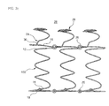
- FIGS. 11 a to 11 c Another type of spring (which has a dual buffer structure to decentrally buffer the larger and smaller loads separately) has been manufactured, and its shape is shown in FIGS. 11 a to 11 c.
- a conventional spring 700 of another type includes a body spring 10 formed in a coil shape whose diameter is gradually increased as it goes toward the top and the bottom from the central portion thereof, an upper end spring 16 wound and extending horizontally at a terminating point of the uppermost winding 12 of the body spring 10 , and a lower end spring 18 wound and extending horizontally at a terminating point of the lowermost winding 14 of the body spring 10 .
- the spring 700 is characterized in that a separate exposure wire spring 20 is formed integrally with the upper end spring 16 in such a fashion as to be disposed above the upper end spring 16 .
- a distal end of the upper end spring 16 is connected integrally with the exposure wire spring 20 , and a distal end of the lower end spring 18 is fixed in such a fashion as to be twisted at the terminating point of the uppermost winding 14 of the body spring 10 .
- the exposure wire spring 20 has a diameter smaller than that of the body spring 10 and is configured to be wound in a coil shape.
- the exposure wire spring 20 also has a resilient force causing compressible deformation thereof relatively easily as compared to the body spring 10 .
- connection end portion a portion 24 (hereinafter, referred to as “connection end portion”) extending from the distal end of the upper end spring 16 to the exposure wire spring 20 runs spirally toward a vertical central axis of the overall spring, the connection end portion 24 and the uppermost wiring 12 for the body spring 10 positioned just below the connection end portion intersect each other when viewed from the top.
- the exposure wire spring 20 buffers/absorbs the load impact.
- the body spring 10 buffers/absorbs the load impact.
- the body spring and the exposure wire spring perform a buffering function thereof separately depending on the magnitude of the load exerted to the bed mattress to thereby provide advantages of preventing the deformation of the spring and prolonging the lifespan of the spring.
- connection end portion 24 for connecting the distal end of the upper end spring 16 and the exposure wire spring 20 to each other is applied with a compression load
- the connection end portion 24 and the uppermost wiring 12 for the body spring 10 positioned just below the connection end portion intersect each other when viewed from the top as described above.
- the connection end portion 24 comes into close contact with the uppermost wiring 12 while descending, to thereby generate the noise due to the contact therebetween.
- the exposure wire spring 20 is compressed and simultaneously the body spring 10 is also compressed, so that the connection end portion 24 also descends upon the compression of the exposure wire spring 20 .
- the connection end portion 24 comes into close contact with the uppermost winding 12 of the body spring 10 with a larger impact, to thereby generate a larger contact noise.
- connection end portion repeatedly comes into close with the uppermost winding of the body spring by friction, it will not be long before the spring itself is deformed.
- the present invention has been made in view of the aforementioned problems occurring in the prior art, and it is an object of the present invention to provide a spring structure for a bed mattress in which the structure of a connection end portion for connecting a body spring and an exposure wire spring to each other is improved such that the connection end portion is not in close contact with an uppermost winding of the body spring, so that when the exposure wire spring is compressed by means of a load exerted to the bed mattress, the connection end portion does not bring into contact with the uppermost winding of the body spring, thereby easily preventing a deformation of the spring due to a frictional contact, preventing a contact noise, and further enhancing the resilient strength of the spring to significantly prolong the lifespan of the spring.
- a spring structure for a bed mattress which comprises: a body spring formed in a coil shape; upper and lower end springs wound and extending horizontally at upper and lower portions of the body spring; a first exposure wire spring formed integrally with the upper end spring in such a fashion as to be disposed above the upper end spring; and a first connection end portion for integrally connecting the upper end spring and the first exposure wire spring to each other.
- This spring structure further includes a first contact-preventing end.
- the first contact-preventing end is formed at the first connection end portion in such a fashion as to be bent upwardly or inclinedly upwardly from a distal end of the upper end spring positioned outwardly from the uppermost winding of the body spring so that the first exposure wire spring may not be in contact with the uppermost winding of the body spring and with the upper end spring.
- a spring structure for a bed mattress which comprises: a body spring formed in a coil shape; upper and lower end springs wound and extending horizontally at upper and lower portions of the body spring; a first exposure wire spring formed integrally with the upper end spring in such a fashion as to be disposed above the upper end spring; and a first connection end portion for integrally connecting the upper end spring and the first exposure wire spring to each other.
- This spring structure further includes a first contact-preventing end and a second contact-preventing end.
- the first contact-preventing end is formed at the first connection end portion in such a fashion as to be bent upwardly or inclinedly upwardly from a distal end of the upper end spring positioned outwardly from the uppermost winding of the body spring so that the first exposure wire spring may not be in contact with the uppermost winding of the body spring and with the upper end spring.
- the second contact-preventing end is formed at the uppermost winding of the body spring positioned below the first contact-preventing end in such a fashion as to be bent upwardly or inclinedly upwardly from a terminating point of the uppermost winding of the body spring to a starting point of the upper end spring.
- a spring structure for a bed mattress which comprises: a body spring formed in a coil shape; upper and lower end springs wound and extending horizontally at upper and lower portions of the body spring; a first exposure wire spring formed integrally with the upper end spring in such a fashion as to be disposed above the upper end spring; a first connection end portion for integrally connecting the upper end spring and the first exposure wire spring to each other; a second exposure wire spring formed integrally with the lower end spring in such a fashion as to be disposed below the lower end spring; and a second connection end portion for integrally connecting the lower end spring and the second exposure wire spring to each other.
- This spring structure further includes a first contact-preventing end and a third contact-preventing end.
- the first contact-preventing end is formed at the first connection end portion in such a fashion as to be bent upwardly or inclinedly upwardly from a distal end of the upper end spring positioned outwardly from an uppermost winding of the body spring so that the first exposure wire spring may not be in contact with the uppermost winding of the body spring and with the upper end spring.
- the third contact-preventing end is formed at the second connection end portion in such a fashion as to be bent downwardly or inclinedly downwardly from a distal end of the lower end spring positioned outwardly from a lowermost winding of the body spring.
- a spring structure for a bed mattress which comprises: a body spring formed in a coil shape; upper and lower end springs wound and extending horizontally at upper and lower portions of the body spring; a first exposure wire spring formed integrally with the upper end spring in such a fashion as to be disposed above the upper end spring; a first connection end portion for integrally connecting the upper end spring and the first exposure wire spring to each other; a second exposure wire spring formed integrally with the lower end spring in such a fashion as to be disposed below the lower end spring; and a second connection end portion for integrally connecting the lower end spring and the second exposure wire spring to each other.
- This spring structure further includes a first contact-preventing end, a second contact-preventing end, a third contact-preventing end, and a fourth contact-preventing end.
- the first contact-preventing end is formed at the first connection end portion in such a fashion as to be bent upwardly or inclinedly upwardly from a distal end of the upper end spring positioned outwardly from an uppermost winding of the body spring, so that the first exposure wire spring may not be in contact with the uppermost winding of the body spring and with the upper end spring.
- the second contact-preventing end is formed at the uppermost winding of the body spring positioned below the first contact-preventing end in such a fashion as to be bent upwardly or inclinedly upwardly from a terminating point of the uppermost winding of the body spring to a starting point of the upper end spring.
- the third contact-preventing end is formed at the second connection end portion in such a fashion as to be bent downwardly or inclinedly downwardly from a distal end of the lower end spring positioned outwardly from a lowermost winding of the body spring.
- the fourth contact-preventing end is formed at the lowermost winding of the body spring positioned above the second contact-preventing end in such a fashion as to be bent downwardly or inclinedly downwardly from a terminating point of the lowermost winding of the body spring to a starting point of the lower end spring.
- a spring structure for a bed mattress which comprises: a body spring formed in a coil shape; upper and lower end springs wound and extending horizontally at upper and lower portions of the body spring; a first exposure wire spring formed integrally with the upper end spring in such a fashion as to be disposed above the upper end spring; and a first connection end portion for integrally connecting the upper end spring and the first exposure wire spring to each other.
- This spring structure further includes a first contact-preventing end, a second contact-preventing end, and a fourth contact-preventing end.
- the first contact-preventing end is formed at the first connection end portion in such a fashion as to be bent upwardly or inclinedly upwardly from a distal end of the upper end spring positioned outwardly from an uppermost winding of the body spring so that the first exposure wire spring may not be in contact with the uppermost winding of the body spring and with the upper end spring.
- the second contact-preventing end is formed at the uppermost winding of the body spring positioned below the first contact-preventing end in such a fashion as to be bent upwardly or inclinedly upwardly from a terminating point of the uppermost winding of the body spring to a starting point of the upper end spring.
- the fourth contact-preventing end is formed at a lowermost winding of the body spring in such a fashion as to be bent downwardly or inclinedly downwardly from a terminating point of the lowermost winding of the body spring to a starting point of the lower end spring.
- each of the first, second, third, and fourth contact-preventing ends may have a height of 5 to 40 mm.
- the inclination angle of the first, second, third, and fourth contact-preventing ends with respect to a vertical axis of the body spring is not greater than 60°.
- FIGS. 1 a , 1 b and 1 c are a perspective view, a front view, and a side view illustrating a spring structure for a bed mattress according to a first embodiment of the present invention
- FIGS. 2 a , 2 b and 2 c are a perspective view, a front view, and a side view illustrating the states where the spring structure according to the first embodiment of the present invention is assembled in a spring assembly;
- FIGS. 3 a and 3 b are a front view and a side view illustrating the compression actions of the spring structure according to the first embodiment of the present invention
- FIGS. 4 a , 4 b and 4 c are a perspective view, a front view, and a side view illustrating a spring structure for a bed mattress according to a second embodiment of the present invention
- FIG. 4 d is a side view illustrating a spring structure for a bed mattress which includes an additional contact-preventing end in the spring of FIG. 4 c;
- FIGS. 5 a , 5 b and 5 c are a perspective view, a front view, and a side view illustrating the states where the spring structure according to the second embodiment of the present invention is assembled in a spring assembly;
- FIGS. 6 a and 6 b are a front view and a side view illustrating the compression actions of the spring structure according to the second embodiment of the present invention.
- FIG. 7 is a side view illustrating a spring structure for a bed mattress according to a third embodiment of the present invention.
- FIG. 8 is a side view illustrating a spring structure for a bed mattress according to a fourth embodiment of the present invention.
- FIGS. 9 a and 9 b are perspective views illustrating a spring structure for a bed mattress according to a fifth embodiment of the present invention, in which an exposure wire spring is connected to an upper end spring thereof, wherein FIG. 9 a shows a state where the exposure wire spring is formed at an upper portion thereof and FIG. 9 b shows a state where the exposure wire spring is formed at upper and lower portions thereof;
- FIGS. 10 a and 10 b are a perspective view and a side view illustrating a prior art spring structure
- FIGS. 11 a , 11 b and 11 c show another prior art spring structure
- FIG. 12 is a perspective view illustrating the prior art spring structure of FIGS. 11 a and 11 b viewed from different angles for the sake of explanation of a disadvantage of the spring;
- FIG. 13 is a cross-section view illustrating the structure of a prior art bed mattress.
- FIGS. 1 a , 1 b and 1 c are a perspective view, a front view, and a side view illustrating a spring structure 100 for a bed mattress according to a first embodiment of the present invention
- FIGS. 2 a , 2 b and 2 c are a perspective view, a front view, and a side view illustrating the states where the spring structure 100 according to the first embodiment of the present invention is assembled in a spring assembly
- FIGS. 3 a and 3 b are a front view and a side view illustrating the compression actions of the spring structure 100 according to the first embodiment of the present invention.
- a spring structure for a bed mattress which can perform a buffering function depending on the magnitude of a load exerted to the bed mattress, comprises a body spring 10 formed in a coil shape, upper and lower end springs 16 and 18 wound and extending horizontally at upper and lower portions of the body spring, an exposure wire spring 20 formed integrally with the upper end spring 16 in such a fashion as to be disposed above the upper end spring 16 , and a connection end portion 24 for integrally connecting the upper end spring and the exposure wire spring to each other.
- the exposure wire spring 20 has a diameter smaller than that of the body spring 10 in such a fashion that the diameter thereof is smaller as it goes toward the top and is configured to be wound in a coil shape.
- a single spring unit for the bed mattress including the body spring 10 and the exposure wire spring 20 is fabricated into a spring assembly 2 , as shown in FIGS. 2 a to 2 c , which is composed of springs arranged apart from one another at regular intervals along row and column directions over the entire area of the bed mattress, and helical coils 26 for securely engaging one side ends of the upper and lower end springs 16 and 18 of adjacent springs for bed mattress with one another.
- the spring structure 100 features that a first contact-preventing end 30 is formed at the connection end portion 24 .
- the first contact-preventing end 30 descends while not coming into close contact with an uppermost winding 12 of the body spring 10 positioned just therebelow, to thereby provide an effect of preventing the contact noise.
- the first contact-preventing end 30 is a wire section bent upwardly (vertically) or inclinedly upwardly (vertically) from a distal end of the upper end spring 16 positioned outwardly from an uppermost winding 12 of the body spring 10 .
- the first contact-preventing end 30 when viewed from the top, the first contact-preventing end 30 is disposed outwardly from an uppermost winding 12 of the body spring 10 without being crossed or overlapped.
- the first contact-preventing end 30 descends while passing by the uppermost winding 12 of the body spring 10 without touching the uppermost winding 12 , thereby preventing the contact between the exposure wire spring 20 and the uppermost winding 12 and a noise due to the contact occurring in the conventional spring.
- connection end portion 24 for integrally interconnecting a distal end of the upper end spring 16 and the exposure wire spring 20 is crossed with the uppermost winding 12 when viewed from the top while being extended spirally.
- connection end portion 24 descends along with compression of the exposure wire spring 20 and comes into close contact with the uppermost winding 12 of the body spring 10 positioned just therebelow, thereby generating the contact noise.
- the first contact-preventing end 30 is formed at the connection end portion 24 .
- the first contact-preventing end 30 descends while passing by the uppermost winding 12 of the body spring 10 positioned just therebelow without touching the uppermost winding 12 , thereby fully eliminating the noise itself that can be otherwise caused if there is such contact between the exposure wire spring 20 and the uppermost winding 12 .
- a spring structure 200 for a bed mattress according to a second embodiment of the present invention will now be described hereinafter.
- FIGS. 4 a , 4 b and 4 c are a perspective view, a front view, and a side view illustrating a spring for a bed mattress according to a second embodiment of the present invention
- FIGS. 5 a , 5 b and 5 c are a perspective view, a front view, and a side view illustrating the states where the spring according to the second embodiment of the present invention is assembled in a spring assembly
- FIGS. 6 a and 6 b are a front view and a side view illustrating the compression actions of the spring according to the second embodiment of the present invention.
- the spring structure 200 according to the second embodiment of the present invention is identical to the spring structure 100 according to the first embodiment, except that it further includes a second contact-preventing end 32 formed at an uppermost winding 12 of the body spring 10 .
- the second contact-preventing end 32 is a connection section formed between a terminating point of the uppermost winding 12 of the body spring 10 and a starting point of the upper end spring 16 in such a fashion as to be bent upwardly or inclinedly upwardly from the terminating point of the uppermost winding 12 to the starting point of the upper end spring 16 .
- a space defined behind the second contact-preventing end 32 (i.e., a space defined just above the uppermost winding of the body spring) is used as a contact-preventing space 34 .
- the reason why the contact-preventing space 34 is formed is that when a load is applied to the bed mattress and simultaneously the exposure wire spring 20 is compressed, the first contact-preventing end 30 is located at the space defined behind the second contact-preventing end 32 while descending so that it does not come into close contact with an uppermost winding 12 of the body spring 10 .
- the spring structure of the second embodiment may further include a fourth contact-preventing end 32 formed at the lowermost winding 14 of the lower end spring 18 to further reinforce the resilient strength of the body spring 10 .
- the first contact-preventing end 30 descends and is located at the space defined behind the second contact-preventing end 32 , i.e., a contact-preventing space 34 so that the first contact-preventing end 30 and the uppermost winding 12 of the body spring 10 do not come into close contact with each other, thereby fundamentally preventing generation of the noise due to the contact between the exposure wire spring 20 and the uppermost winding 12 .
- the fourth contact-preventing end 32 formed at the lowermost winding 14 of the body spring 10 acts to support the body spring 10 so as to further reinforce the resilient strength of the body spring 10 .
- the first contact-preventing end 30 passes by the contact-preventing space 34 of the second contact-preventing end 32 and then descends further toward the uppermost winding 12 . But at this time, the first contact-preventing end 30 descends outwardly from the uppermost winding 12 of the body spring 10 without touching the uppermost winding 12 , so that although a larger load is exerted to the bed mattress, there is not any contact between the first contact-preventing end 30 and the uppermost winding 12 of the body spring 10 .
- FIG. 7 is a side view illustrating a spring structure 300 for a bed mattress according to a third embodiment of the present invention.
- the spring structure of the third embodiment is identical to the spring structure of the first embodiment except that it further includes a fourth contact-preventing end.
- the spring structure 300 according to the third embodiment is identical to that of the first embodiment except that it further includes a third contact-preventing end. More specifically, an upper exposure wire spring 20 is connected integrally with the upper end spring 16 in such a fashion as to be disposed above the upper end spring 16 and a lower exposure wire spring 20 is connected integrally with the lower end spring 18 in such a fashion as to be disposed below the lower end spring 18 .
- the spring structure 300 further includes a third contact-preventing end 30 is formed between the lower end spring 18 and the lower exposure wire spring 20 for the purpose of prevention of the noise due to any contact therebetween.
- FIG. 8 is a side view illustrating a spring structure 400 for a bed mattress according to a fourth embodiment of the present invention.
- the spring structure 400 of the fourth embodiment is identical to that of the second embodiment except that it further includes a third contact-preventing end and a fourth contact-preventing end.
- an upper exposure wire spring 20 is connected integrally with the upper end spring 16 in such a fashion as to be disposed above the upper end spring 16 and a lower exposure 20 is connected integrally with the lower end spring 18 in such a fashion as to be disposed below the lower end spring 18 .
- the spring structure 400 further includes a third contact-preventing end 30 formed between the lower end spring 18 and the lower exposure wire spring 20 , and a fourth contact-preventing end 32 formed between the lower end spring 18 and the lowermost winding 14 of the body spring 10 .
- FIGS. 9 a and 9 b are perspective views illustrating a spring structure 500 for a bed mattress according to a fifth embodiment of the present invention, in which an exposure wire spring 20 is connected to an upper end portion of a conventional coil spring.
- the spring structure 500 according to the fifth embodiment shown in FIGS. 9 a and 9 b is characterized in that the exposure wire spring 20 is connected integrally with the upper end spring 16 of a conventional coil shape in such a fashion as to be disposed above the upper end spring 16 , or integrally with both the upper end spring 16 and the lower end spring 18 in such a fashion as to be disposed above the upper end spring 16 and below the lower end spring 18 .
- the spring structure 500 includes a first contact-preventing end 30 formed between the upper end spring 16 and the exposure wire spring 20 .
- the spring structure 500 includes, in addition to the first contact-preventing end 30 , a third contact-preventing end 30 between the lower end spring 18 and a lower exposure wire spring 20 .
- the exposure wire spring 20 may be connected to the upper end spring of the body spring 10 , or the upper end spring and the lower end spring of the body spring 10 irrespective of the kind of the spring.
- the first contact-preventing end 30 alone is formed or the first contact-preventing end 30 and at least one of the second, third, and fourth contact-preventing ends 30 and 32 are formed to prevent the contact between the springs and a resulting noise.
- the height of the first and second contact-preventing ends is in the range between 5 to 40 mm.
- the reason of limiting the height is that if the height thereof is less than 5 mm, the formation itself of the first and second contact-preventing ends 30 and 32 are difficult, and if the height thereof is more than 40 mm, the intrinsic property of the spring is lost.
- the inclination angle of the first and second contact-preventing ends 30 and 32 with respect to a vertical axis of the body spring 10 is limited to the range between 0° and 60°.
- the reason of limiting the inclination angle is that if the inclination angle is 0°, the rigidity of the exposure wire spring 20 is the most favorable, and if the inclination angle is more than 60°, the rigidity of the exposure wire spring 20 becomes weak and the impact-absorbing capacity of the exposure wire spring 20 is deteriorated.
- first contact-preventing end 30 at a connection portion extending between the upper end spring 16 and the exposure wire spring 20 positioned above the upper end spring 16
- second contact-preventing end 32 at a portion extending from the uppermost winding 12 of the body spring 10 to the upper end spring 16
- third contact-preventing end 30 at a connection portion extending between the lower end spring 18 and the exposure wire spring 20 positioned below the lower end spring 18
- fourth contact-preventing end 32 at a portion extending from the lower end spring 18 to the lowermost winding 14 of the body spring 10
- the body spring and the exposure wire spring perform a buffering function thereof separately depending on the magnitude of the load exerted to the bed mattress to thereby provide advantages of preventing the deformation of the spring and prolonging the lifespan of the spring.
- the rigidity of the spring is further enhanced by means of the first contact preventing end 30 , or the first and second contact-preventing end 30 and 32 , to thereby fundamentally prevent the contact noise.
- connection end portion for connecting a body spring and an exposure wire spring to each other is improved such that the connection end portion is not in close contact with an uppermost winding of the body spring, so that the following merits are provided:
- the first contact-preventing end is formed at a connection end portion extending between the body spring and the upper exposure wire spring, so that when the exposure wire spring is compressed by means of a load exerted to the bed mattress, the first contact-preventing end does not bring into contact with the uppermost winding of the body spring while descending, thereby easily preventing a deformation of the spring due to a frictional contact and fundamentally preventing a contact noise.
- the second contact-preventing end is further formed between the upper end spring and the body spring in addition to the first contact-preventing end, so that the first contact-preventing end is positioned at the space defined behind the second contact-preventing end while descending or passes by the uppermost winding of the body spring without touching the uppermost winding while descending, thereby further easily preventing a deformation of the spring due to a frictional contact and fundamentally preventing a contact noise.
- the first contact-preventing end is formed at a connection end portion extending between the body spring and the exposure wire spring, thereby further enhancing the resilient strength of the spring to significantly prolong the lifespan of the spring accordingly.
Abstract
Description
Claims (13)
Applications Claiming Priority (2)
| Application Number | Priority Date | Filing Date | Title |
|---|---|---|---|
| KR1020060023307A KR100717543B1 (en) | 2006-03-14 | 2006-03-14 | Spring structure for mattress |
| KR10-2006-0023307 | 2006-03-14 |
Publications (2)
| Publication Number | Publication Date |
|---|---|
| US20070216076A1 US20070216076A1 (en) | 2007-09-20 |
| US7677541B2 true US7677541B2 (en) | 2010-03-16 |
Family
ID=38217732
Family Applications (1)
| Application Number | Title | Priority Date | Filing Date |
|---|---|---|---|
| US11/445,109 Active 2028-09-05 US7677541B2 (en) | 2006-03-14 | 2006-05-31 | Spring structure for bed mattress |
Country Status (10)
| Country | Link |
|---|---|
| US (1) | US7677541B2 (en) |
| EP (1) | EP1834547B1 (en) |
| JP (1) | JP4264489B2 (en) |
| KR (1) | KR100717543B1 (en) |
| CN (2) | CN100523539C (en) |
| AT (1) | ATE413829T1 (en) |
| BR (1) | BRPI0602620B1 (en) |
| CA (1) | CA2550303C (en) |
| DE (1) | DE602006003624D1 (en) |
| ES (1) | ES2317429T3 (en) |
Cited By (8)
| Publication number | Priority date | Publication date | Assignee | Title |
|---|---|---|---|---|
| US20090106908A1 (en) * | 2007-10-29 | 2009-04-30 | Dreamwell, Ltd. | Asymmetrical combined cylindrical and conical springs |
| US20130099435A1 (en) * | 2010-06-30 | 2013-04-25 | Mitsubishi Steel Mfg Co., Ltd. | Coil Spring |
| US8979079B2 (en) | 2010-11-09 | 2015-03-17 | Dreamwell, Ltd. | Spring coils for innerspring assemblies and methods of manufacture |
| EP2853176A1 (en) | 2013-09-25 | 2015-04-01 | Yoo Soo Ahn | High tension coil spring for bed mattress having means for preventing frictional noise |
| EP2853175A1 (en) | 2013-09-25 | 2015-04-01 | Yoo Soo Ahn | High Tension Coil Spring Structure for Bed Mattress Having Means for Preventing Friction Noise |
| USD739162S1 (en) | 2012-08-22 | 2015-09-22 | L&P Swiss Holding Ag | Coil spring |
| US9364095B2 (en) | 2012-07-26 | 2016-06-14 | L&P Swiss Holding Ag | Spring core having a fully active spring and method of manufacturing the same |
| US20220007850A1 (en) * | 2018-11-16 | 2022-01-13 | Oy Sda Finland Ltd. | Method of forming an orthopedic mattress and orthopedic mattress |
Families Citing this family (13)
| Publication number | Priority date | Publication date | Assignee | Title |
|---|---|---|---|---|
| US7404223B2 (en) * | 2004-08-28 | 2008-07-29 | Sealy Technology Llc | Innerspring coils and innersprings with non-helical segments |
| KR100717543B1 (en) * | 2006-03-14 | 2007-05-15 | 주식회사 에이스침대 | Spring structure for mattress |
| KR100820579B1 (en) | 2007-05-15 | 2008-04-08 | 주식회사 에이스침대 | Device for absorbing the load of coil spring for bed mattress |
| KR20120039814A (en) * | 2010-10-18 | 2012-04-26 | 안유수 | Pocket spring structure for mattress |
| WO2013005867A1 (en) * | 2011-07-01 | 2013-01-10 | 주식회사 에이스침대 | Spring for a bed mattress |
| GB2495499B (en) * | 2011-10-11 | 2019-02-06 | Hs Products Ltd | Hybrid spring |
| GB2506104B (en) | 2012-08-10 | 2018-12-12 | Hs Products Ltd | Resilient unit with different major surfaces |
| KR101355896B1 (en) * | 2013-03-28 | 2014-01-28 | 안유수 | Coil spring of bed matress with means for preventing the friction noise |
| WO2016122453A1 (en) * | 2015-01-27 | 2016-08-04 | Sealy Technology, Llc | Coiled spring with variable resistance and mattresses including the same |
| KR101727554B1 (en) | 2015-03-06 | 2017-04-17 | (주) 비엠비 | Mettress |
| US11480228B2 (en) | 2016-12-15 | 2022-10-25 | Sealy Technology, Llc | Open coil spring assemblies |
| GB201708635D0 (en) | 2017-05-31 | 2017-07-12 | Hs Products Ltd | Pocketed spring unit and method manufacture |
| GB201708639D0 (en) | 2017-05-31 | 2017-07-12 | Hs Products Ltd | Transportation Apparatus and method |
Citations (16)
| Publication number | Priority date | Publication date | Assignee | Title |
|---|---|---|---|---|
| US198833A (en) * | 1878-01-01 | Improvement in bed-springs | ||
| US1756270A (en) * | 1928-05-10 | 1930-04-29 | Percival L Whittenberger | Spring wheel |
| US2668278A (en) * | 1950-08-11 | 1954-02-02 | Crouse Hinds Co | Resiliently mounted lamp receptacle |
| US3533114A (en) * | 1968-07-12 | 1970-10-13 | Holland Wire Products Co Inc | Coil spring configuration |
| JPS5683631A (en) * | 1979-12-11 | 1981-07-08 | Kayaba Ind Co Ltd | Coiled spring |
| US4371152A (en) * | 1980-01-25 | 1983-02-01 | Hoover Universal, Inc. | Box spring assembly with improved spring installation capability |
| US4555097A (en) * | 1983-05-16 | 1985-11-26 | Leggett & Platt, Incorporated | Combination round coil spring and rectangular torsion coil spring assembly |
| US4726572A (en) * | 1986-05-16 | 1988-02-23 | Sealy, Incorporated | Spring coil and spring assembly |
| US4817924A (en) * | 1983-09-20 | 1989-04-04 | Alan Thoenen | Spring core for a mattress |
| US5575460A (en) * | 1995-01-09 | 1996-11-19 | Spuehl Ag | Spring core for a mattress |
| US5713088A (en) * | 1994-10-21 | 1998-02-03 | Ohio Mattress Company Licensing And Components Group | Innerspring construction with springs having free terminal convolutions |
| US5868383A (en) * | 1997-03-27 | 1999-02-09 | L&P Property Management Company | Multiple rate coil spring assembly |
| US6256820B1 (en) * | 2000-02-09 | 2001-07-10 | L&P Property Management Company | Multilayered pocketed bedding or seating product |
| US7178187B2 (en) * | 2004-08-28 | 2007-02-20 | Sealy Technology Llc | Asymmetric spring components and innersprings for one-sided mattresses |
| US20070235915A1 (en) * | 2006-04-07 | 2007-10-11 | Ace Bed Co., Ltd. | Spring structure having contact-preventing and rigidity-reinforcing function for bed mattress |
| US7404223B2 (en) * | 2004-08-28 | 2008-07-29 | Sealy Technology Llc | Innerspring coils and innersprings with non-helical segments |
Family Cites Families (9)
| Publication number | Priority date | Publication date | Assignee | Title |
|---|---|---|---|---|
| US3942776A (en) * | 1974-12-23 | 1976-03-09 | E. R. Carpenter Company, Inc. | Upholstery coil spring |
| JPS5853216B2 (en) * | 1981-03-04 | 1983-11-28 | フランスベッド株式会社 | spring structure |
| AT388093B (en) * | 1982-04-30 | 1989-04-25 | Spuehl Ag | SPRING CORE FOR MATTRESSES AND UPHOLSTERY FURNITURE |
| GB9102245D0 (en) * | 1991-02-01 | 1991-03-20 | Elson & Robbins Limited | Spring assembly for a cushion or mattress |
| JPH1189678A (en) * | 1997-09-16 | 1999-04-06 | Nippon Bed Seizo Kk | Coil spring for mattress |
| KR100440712B1 (en) * | 2002-11-18 | 2004-07-19 | 주식회사 에이스침대 | Method for setting the spring assembly using in matress |
| US6983503B2 (en) * | 2003-09-09 | 2006-01-10 | Ace Bed Co., Ltd. | Apparatus for packing free terminal convolutions of spring assembly used in mattress |
| CN1316931C (en) * | 2005-01-08 | 2007-05-23 | 雅思床褥家具(广州)有限公司 | Helical spring configuration structure for mattress spring assembly |
| KR100717543B1 (en) * | 2006-03-14 | 2007-05-15 | 주식회사 에이스침대 | Spring structure for mattress |
-
2006
- 2006-03-14 KR KR1020060023307A patent/KR100717543B1/en active IP Right Grant
- 2006-05-31 US US11/445,109 patent/US7677541B2/en active Active
- 2006-06-15 CA CA002550303A patent/CA2550303C/en active Active
- 2006-06-16 AT AT06115601T patent/ATE413829T1/en not_active IP Right Cessation
- 2006-06-16 ES ES06115601T patent/ES2317429T3/en active Active
- 2006-06-16 DE DE602006003624T patent/DE602006003624D1/en active Active
- 2006-06-16 EP EP06115601A patent/EP1834547B1/en active Active
- 2006-06-19 JP JP2006168717A patent/JP4264489B2/en active Active
- 2006-06-26 CN CNB2006100908089A patent/CN100523539C/en active Active
- 2006-06-30 BR BRPI0602620A patent/BRPI0602620B1/en active IP Right Grant
- 2006-12-29 CN CNU2006201756572U patent/CN201041212Y/en not_active Expired - Lifetime
Patent Citations (16)
| Publication number | Priority date | Publication date | Assignee | Title |
|---|---|---|---|---|
| US198833A (en) * | 1878-01-01 | Improvement in bed-springs | ||
| US1756270A (en) * | 1928-05-10 | 1930-04-29 | Percival L Whittenberger | Spring wheel |
| US2668278A (en) * | 1950-08-11 | 1954-02-02 | Crouse Hinds Co | Resiliently mounted lamp receptacle |
| US3533114A (en) * | 1968-07-12 | 1970-10-13 | Holland Wire Products Co Inc | Coil spring configuration |
| JPS5683631A (en) * | 1979-12-11 | 1981-07-08 | Kayaba Ind Co Ltd | Coiled spring |
| US4371152A (en) * | 1980-01-25 | 1983-02-01 | Hoover Universal, Inc. | Box spring assembly with improved spring installation capability |
| US4555097A (en) * | 1983-05-16 | 1985-11-26 | Leggett & Platt, Incorporated | Combination round coil spring and rectangular torsion coil spring assembly |
| US4817924A (en) * | 1983-09-20 | 1989-04-04 | Alan Thoenen | Spring core for a mattress |
| US4726572A (en) * | 1986-05-16 | 1988-02-23 | Sealy, Incorporated | Spring coil and spring assembly |
| US5713088A (en) * | 1994-10-21 | 1998-02-03 | Ohio Mattress Company Licensing And Components Group | Innerspring construction with springs having free terminal convolutions |
| US5575460A (en) * | 1995-01-09 | 1996-11-19 | Spuehl Ag | Spring core for a mattress |
| US5868383A (en) * | 1997-03-27 | 1999-02-09 | L&P Property Management Company | Multiple rate coil spring assembly |
| US6256820B1 (en) * | 2000-02-09 | 2001-07-10 | L&P Property Management Company | Multilayered pocketed bedding or seating product |
| US7178187B2 (en) * | 2004-08-28 | 2007-02-20 | Sealy Technology Llc | Asymmetric spring components and innersprings for one-sided mattresses |
| US7404223B2 (en) * | 2004-08-28 | 2008-07-29 | Sealy Technology Llc | Innerspring coils and innersprings with non-helical segments |
| US20070235915A1 (en) * | 2006-04-07 | 2007-10-11 | Ace Bed Co., Ltd. | Spring structure having contact-preventing and rigidity-reinforcing function for bed mattress |
Cited By (11)
| Publication number | Priority date | Publication date | Assignee | Title |
|---|---|---|---|---|
| US20090106908A1 (en) * | 2007-10-29 | 2009-04-30 | Dreamwell, Ltd. | Asymmetrical combined cylindrical and conical springs |
| US9161634B2 (en) | 2007-10-29 | 2015-10-20 | Dreamwell, Ltd. | Asymmetrical combined cylindrical and conical springs |
| US20130099435A1 (en) * | 2010-06-30 | 2013-04-25 | Mitsubishi Steel Mfg Co., Ltd. | Coil Spring |
| US10138970B2 (en) * | 2010-06-30 | 2018-11-27 | Mitsubishi Steel Mfg. Co., Ltd. | Coil spring |
| US8979079B2 (en) | 2010-11-09 | 2015-03-17 | Dreamwell, Ltd. | Spring coils for innerspring assemblies and methods of manufacture |
| US9364095B2 (en) | 2012-07-26 | 2016-06-14 | L&P Swiss Holding Ag | Spring core having a fully active spring and method of manufacturing the same |
| USD739162S1 (en) | 2012-08-22 | 2015-09-22 | L&P Swiss Holding Ag | Coil spring |
| USD774818S1 (en) | 2012-08-22 | 2016-12-27 | L&P Swiss Holding Ag | Coil spring |
| EP2853176A1 (en) | 2013-09-25 | 2015-04-01 | Yoo Soo Ahn | High tension coil spring for bed mattress having means for preventing frictional noise |
| EP2853175A1 (en) | 2013-09-25 | 2015-04-01 | Yoo Soo Ahn | High Tension Coil Spring Structure for Bed Mattress Having Means for Preventing Friction Noise |
| US20220007850A1 (en) * | 2018-11-16 | 2022-01-13 | Oy Sda Finland Ltd. | Method of forming an orthopedic mattress and orthopedic mattress |
Also Published As
| Publication number | Publication date |
|---|---|
| EP1834547A1 (en) | 2007-09-19 |
| JP2007244841A (en) | 2007-09-27 |
| CN101038015A (en) | 2007-09-19 |
| EP1834547B1 (en) | 2008-11-12 |
| CA2550303C (en) | 2009-07-21 |
| US20070216076A1 (en) | 2007-09-20 |
| JP4264489B2 (en) | 2009-05-20 |
| BRPI0602620B1 (en) | 2017-06-06 |
| DE602006003624D1 (en) | 2008-12-24 |
| ES2317429T3 (en) | 2009-04-16 |
| CN201041212Y (en) | 2008-03-26 |
| CA2550303A1 (en) | 2007-09-14 |
| KR100717543B1 (en) | 2007-05-15 |
| CN100523539C (en) | 2009-08-05 |
| BRPI0602620A (en) | 2007-11-06 |
| ATE413829T1 (en) | 2008-11-15 |
Similar Documents
| Publication | Publication Date | Title |
|---|---|---|
| US7677541B2 (en) | Spring structure for bed mattress | |
| US8109490B2 (en) | Spring structure having contact-preventing and rigidity-reinforcing function for bed mattress | |
| EP2441353A1 (en) | Pocket spring structure for bed mattress | |
| US20030074736A1 (en) | Innerspring assembly | |
| EP2853176A1 (en) | High tension coil spring for bed mattress having means for preventing frictional noise | |
| US20170172309A1 (en) | High Tension Coil Spring Structure for Bed Mattress having Means for Preventing Friction Noise | |
| KR200417435Y1 (en) | Spring structure for mattress | |
| KR100970910B1 (en) | Reinforcement structure for spring assembly for bed mattress | |
| US20220232992A1 (en) | High tension coil spring structure for bed mattress having means for preventing friction noise | |
| KR100820579B1 (en) | Device for absorbing the load of coil spring for bed mattress | |
| MXPA06011452A (en) | Spring structure for bed mattress | |
| WO2013005867A1 (en) | Spring for a bed mattress | |
| KR20110135577A (en) | Spring structure for mattress | |
| KR200421339Y1 (en) | Spring structure for mattress | |
| KR101310780B1 (en) | Stack spring structure for mattress |
Legal Events
| Date | Code | Title | Description |
|---|---|---|---|
| AS | Assignment |
Owner name: ACE BED CO., LTD.,KOREA, REPUBLIC OF Free format text: ASSIGNMENT OF ASSIGNORS INTEREST;ASSIGNOR:AHN, YOO S.;REEL/FRAME:017968/0394 Effective date: 20060516 Owner name: ACE BED CO., LTD., KOREA, REPUBLIC OF Free format text: ASSIGNMENT OF ASSIGNORS INTEREST;ASSIGNOR:AHN, YOO S.;REEL/FRAME:017968/0394 Effective date: 20060516 |
|
| AS | Assignment |
Owner name: AHN, YOO SOO, KOREA, REPUBLIC OF Free format text: ASSIGNMENT OF ASSIGNORS INTEREST;ASSIGNOR:ACE BED CO., LTD.;REEL/FRAME:022786/0692 Effective date: 20090514 Owner name: AHN, YOO SOO,KOREA, REPUBLIC OF Free format text: ASSIGNMENT OF ASSIGNORS INTEREST;ASSIGNOR:ACE BED CO., LTD.;REEL/FRAME:022786/0692 Effective date: 20090514 |
|
| STCF | Information on status: patent grant |
Free format text: PATENTED CASE |
|
| FEPP | Fee payment procedure |
Free format text: PAYOR NUMBER ASSIGNED (ORIGINAL EVENT CODE: ASPN); ENTITY STATUS OF PATENT OWNER: LARGE ENTITY |
|
| FPAY | Fee payment |
Year of fee payment: 4 |
|
| MAFP | Maintenance fee payment |
Free format text: PAYMENT OF MAINTENANCE FEE, 8TH YEAR, LARGE ENTITY (ORIGINAL EVENT CODE: M1552) Year of fee payment: 8 |
|
| MAFP | Maintenance fee payment |
Free format text: PAYMENT OF MAINTENANCE FEE, 12TH YEAR, LARGE ENTITY (ORIGINAL EVENT CODE: M1553); ENTITY STATUS OF PATENT OWNER: LARGE ENTITY Year of fee payment: 12 |
|
| AS | Assignment |
Owner name: ACE BED CO., LTD., KOREA, REPUBLIC OF Free format text: ASSIGNMENT OF ASSIGNORS INTEREST;ASSIGNOR:AHN, YOO SOO;REEL/FRAME:064155/0452 Effective date: 20230703 |