US767597A - Liquid-fuel distributer. - Google Patents
Liquid-fuel distributer. Download PDFInfo
- Publication number
- US767597A US767597A US1904198272A US767597A US 767597 A US767597 A US 767597A US 1904198272 A US1904198272 A US 1904198272A US 767597 A US767597 A US 767597A
- Authority
- US
- United States
- Prior art keywords
- tank
- pipe
- fuel
- air
- valve
- Prior art date
- Legal status (The legal status is an assumption and is not a legal conclusion. Google has not performed a legal analysis and makes no representation as to the accuracy of the status listed.)
- Expired - Lifetime
Links
Images
Classifications
-
- B—PERFORMING OPERATIONS; TRANSPORTING
- B01—PHYSICAL OR CHEMICAL PROCESSES OR APPARATUS IN GENERAL
- B01J—CHEMICAL OR PHYSICAL PROCESSES, e.g. CATALYSIS OR COLLOID CHEMISTRY; THEIR RELEVANT APPARATUS
- B01J4/00—Feed or outlet devices; Feed or outlet control devices
- B01J4/001—Feed or outlet devices as such, e.g. feeding tubes
-
- Y—GENERAL TAGGING OF NEW TECHNOLOGICAL DEVELOPMENTS; GENERAL TAGGING OF CROSS-SECTIONAL TECHNOLOGIES SPANNING OVER SEVERAL SECTIONS OF THE IPC; TECHNICAL SUBJECTS COVERED BY FORMER USPC CROSS-REFERENCE ART COLLECTIONS [XRACs] AND DIGESTS
- Y10—TECHNICAL SUBJECTS COVERED BY FORMER USPC
- Y10T—TECHNICAL SUBJECTS COVERED BY FORMER US CLASSIFICATION
- Y10T137/00—Fluid handling
- Y10T137/2931—Diverse fluid containing pressure systems
- Y10T137/3115—Gas pressure storage over or displacement of liquid
- Y10T137/3124—Plural units
-
- Y—GENERAL TAGGING OF NEW TECHNOLOGICAL DEVELOPMENTS; GENERAL TAGGING OF CROSS-SECTIONAL TECHNOLOGIES SPANNING OVER SEVERAL SECTIONS OF THE IPC; TECHNICAL SUBJECTS COVERED BY FORMER USPC CROSS-REFERENCE ART COLLECTIONS [XRACs] AND DIGESTS
- Y10—TECHNICAL SUBJECTS COVERED BY FORMER USPC
- Y10T—TECHNICAL SUBJECTS COVERED BY FORMER US CLASSIFICATION
- Y10T137/00—Fluid handling
- Y10T137/794—With means for separating solid material from the fluid
Definitions
- This invention relates to an improved liquidfuel distributerfor heating and lighting systems, and has for its object to provide a simple, inexpensive, and efficient device of this character for distributing gasolene or other liquid hydrocarbon under pressure to a large number of lamps, stoves, or other devices consuming oil.
- a further object of the invention is to provide a main fuel-supply tank and an auxiliary or reserve tank which also serves as a reservoir for compressed air, and, further, to provide a system of valves by means of which the main supply-tank may be cut ofi for a limited time from the auxiliary tank to thereby permit the former to be refilled without affecting the lights.
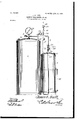
- FIG. 1 is a longitudinal sectional view of a liquid-fuel distributer constructed in accordance with my invention.
- the main fuel-supply tank 5 may be of any desired shape, being preferably cylindrical in form, as shown, and provided with a fillingorifice 6, through which the gasolene or other liquid hydrocarbon is introduced into the receptacle.
- the fuel-tank 5 is connected by an air-supply pipe 7 to an auxiliary or reserve fuel-tank 8,
- the air-supply pipe 7 passes through the fuel-tank 5, as shown, and secured in any suitable manner to the end of said pipe is a main fuel-supply pipe 11, which extends upwardly parallel with the tank 8 and terminates in a discharge pipe or nozzle 12, provided with a cut-off valve 13 for regulating the discharge of oil from said pipe to the lamps or burners.
- the fuel-supply pipe 11 is provided with a T- coupling 14, in which is threaded an auxiliary supply-pipe 15, which passes through the top of the tank 8 and extends to a point near the bottom thereof, as shown, and through which the oil in the tank 8 is forced under pressure to the lamps or burners when the supply of gasolene in the tank 5 is exhausted or while the latter is being refilled.
- a suitable valve 16 controls the supply of liquid from the auxiliary tank 8 to the nozzle 12, said valve being normally closed, so as to prevent the escape of oil while the gasolene is being supplied to the burners from the main tank 5.
- a filter 16 Interposed between the nozzle 12 and the coupling 14. is a filter 16, filled with sand or other suitable granular material, through-which the oil passes from the tanks 5 and 8 on its way to the lamps.
- a valve 17 is arranged in the main supply-pipe 11 for preventing the flow of oil from the auxiliary tank 8 through said pipe while the main tank 5 is being filled.
- the air-pipe 7 is provided with a suitable pressure-gage 18 for indicating the pressure of the air within the tank 8, said pipe being also provided with an opening 20, through which the air is admitted to the tank 5, and a plurality of openings 21 to permit the escape of oil from the bottom of said tank through the pipe 11 to the lamps.
- valves 22 and 23 working in a common valve-casing 24, mounted in the air-supply pipe 7 above the main fuel-tank, as shown.
- the valvecasing 24 is provided with an exhaust-opening 25, through which the air from the tank 5 escapes when the valve 22 is open and the valve 23 closed, thereby reducing the pres-,
- main tank 5 may be readily refilled when necessary without affecting the lights by-closing the valves 17 and 23 and opening the valve 22, which permits the air within the tank to escape through the opening in the valve-casing 24:, thereby reducing the pressure in said tank and allowing a fresh supply of oil to be I introduced through the filling-orifice.
- supply-pipe may be connected with the burners in any suitable manner and the apparatus located in a cellar, basement, outhouse, or other convenient place remote from said burners. 5
- the combination with amain fuel-tank, of an auxiliary fuel-tank also serving as a reservoir for compressed air, an air-pipe one end of which is connected to the auxiliary tank and the opposite end thereof extended within the main tank and provided with a dischargeopening, a fuel-conducting pipe leading from each tank to a common discharge-pipe, valves mounted in the conducting-pipes for independently controlling the discharge of fuel from said tanks, a valve-casing provided with an exhaust-opening arranged in the air-pipe, and a pair of valves mounted in the valvecasing, one for controlling the flow of air from the main to the auxiliary tank and the other for permitting the escape of air from the former tank through the exhaust-opening when the opposite valve is closed.
Description
No. 767,597. PATENTED AUG. 16, 1904. J. E. RAFF'.
LIQUID FUEL DISTRIBUTER.
APPLIOATION F ILED MAE. 15, 1904.
N0 MODEL.
v .75 2% J6. 5 c 14 T #fl. J0 J5 24 J2 ZJ I 2 E t l l i 2 1 1 1 I I y I JwizeJEZZeLff ltnesses nvenkor.
JAMES E. RAFF, OF MONTOUR, IOWVA,
Patented August 16, 1904r PATENT OFFIC ASSIGNOR OF ONE-HALF TO NATHAN W. LUNDY, OF MARSHALLTOWN, IOlV A.
LIQUID-FUEL DISTRIBUTER.
SPECIFICATION forming part of Letters Patent No. 767,597, dated August 16, 1904.
Application filed March 15, 1904.
To a, whom, it nuty concern:
Be it known that 1, JAMES E. RAFF, a citizen of the United States, residing at Montour, in the county of Tama and State of Iowa, have invented a new and usefulLiquid-Fuel Distributer for Heating and Lighting Systems, of which the following is a specification.
This invention relates to an improved liquidfuel distributerfor heating and lighting systems, and has for its object to provide a simple, inexpensive, and efficient device of this character for distributing gasolene or other liquid hydrocarbon under pressure to a large number of lamps, stoves, or other devices consuming oil.
A further object of the invention is to provide a main fuel-supply tank and an auxiliary or reserve tank which also serves as a reservoir for compressed air, and, further, to provide a system of valves by means of which the main supply-tank may be cut ofi for a limited time from the auxiliary tank to thereby permit the former to be refilled without affecting the lights.
The invention consists in the construction and novel combination and arrangements of parts hereinafter fully described, illustrated in the accompanying drawing, and pointed out in the claims hereto appended, it being understood that various changes in form, proportion, and minor details of construction may be resorted to without departing from the principle or sacrificing any of the advantages of this invention.
In the accompanying drawing, forming a part of this specification, the figure is a longitudinal sectional view of a liquid-fuel distributer constructed in accordance with my invention.
Similar numerals of reference indicate corresponding parts in the drawing.
The main fuel-supply tank 5 may be of any desired shape, being preferably cylindrical in form, as shown, and provided with a fillingorifice 6, through which the gasolene or other liquid hydrocarbon is introduced into the receptacle.
The fuel-tank 5 is connected by an air-supply pipe 7 to an auxiliary or reserve fuel-tank 8,
Serial No. 198,272. (No model.)
which also serves as a reservoir for compressed air, said an being pumped 1nto the tank 1n any suitable manner through a check-valve 9 in the end of the pipe 7, while the liquid fuel is supplied to the tank through an orifice 10 in the top thereof.
The air-supply pipe 7 passes through the fuel-tank 5, as shown, and secured in any suitable manner to the end of said pipe is a main fuel-supply pipe 11, which extends upwardly parallel with the tank 8 and terminates in a discharge pipe or nozzle 12, provided with a cut-off valve 13 for regulating the discharge of oil from said pipe to the lamps or burners. The fuel-supply pipe 11 is provided with a T- coupling 14, in which is threaded an auxiliary supply-pipe 15, which passes through the top of the tank 8 and extends to a point near the bottom thereof, as shown, and through which the oil in the tank 8 is forced under pressure to the lamps or burners when the supply of gasolene in the tank 5 is exhausted or while the latter is being refilled. A suitable valve 16 controls the supply of liquid from the auxiliary tank 8 to the nozzle 12, said valve being normally closed, so as to prevent the escape of oil while the gasolene is being supplied to the burners from the main tank 5. Interposed between the nozzle 12 and the coupling 14. is a filter 16, filled with sand or other suitable granular material, through-which the oil passes from the tanks 5 and 8 on its way to the lamps. A valve 17 is arranged in the main supply-pipe 11 for preventing the flow of oil from the auxiliary tank 8 through said pipe while the main tank 5 is being filled.
The air-pipe 7 is provided with a suitable pressure-gage 18 for indicating the pressure of the air within the tank 8, said pipe being also provided with an opening 20, through which the air is admitted to the tank 5, and a plurality of openings 21 to permit the escape of oil from the bottom of said tank through the pipe 11 to the lamps.
As a means for controlling the supply of air from the reserve tank or reservoir 8 to the fuel-tank 5 and for permitting the escape of air from the latter tank preparatory to refilling the same I provide a pair of valves 22 and 23, working in a common valve-casing 24, mounted in the air-supply pipe 7 above the main fuel-tank, as shown. The valvecasing 24 is provided with an exhaust-opening 25, through which the air from the tank 5 escapes when the valve 22 is open and the valve 23 closed, thereby reducing the pres-,
first filled with gasolene or other liquid hydrocarbon to be distributed under pressure and a relatively small quantity of the oil introduced in the auxiliary tank 8, the latter tank being then charged with air from acompressor or other suitable source of supply through the check-valve 9. The valves 16 and 22 being closed and the valves 13, 17, and T 23 open, the airunder pressure from the tank 1 8 will flow through the air-supply pipe 7 to the main fuel-tank'5, forcing the oil through the pipe 11, filter 16, and valve 13 to the lamps or burners. When the oil in the main tank 5 is all consumed, a fresh supply may be had without the necessity of immediately I refilling said tank by closing the valves 17 and 23 and opening the valve 16, thereby permitting the oil in the auxiliary tank 8 to flow through theauXi-liarysupply-pipe 1'5 and filter 16 and thence to the burners. The
It will be understood that the supply-pipe may be connected with the burners in any suitable manner and the apparatus located in a cellar, basement, outhouse, or other convenient place remote from said burners. 5
Having thus described the invention, what is claimed is- 1. In an apparatus of theclassdescribed, the combination with a main fuel-tank, of an auxiliaryfuel-tank serving also as areservoir for compressed air, an air-pipe connecting saidi tanks, a fuel-conducting pipe leading from} each tank to a common discharge-pipe, a filter mounted in said discharge-pipe, valves mounted in the fuel-conducting pipes for independently controlling the discharge of fuel from said tanks to the filter, and a pair of valves mounted in a common valve-casing, one for controlling the flow of air from the main to the auxiliary tank and the other for permitting the escape of air from the main tank when the opposite valve is closed.
2. In an apparatus of the class described, the combination with amain fuel-tank, of an auxiliary fuel-tank also serving as a reservoir for compressed air, an air-pipe one end of which is connected to the auxiliary tank and the opposite end thereof extended within the main tank and provided with a dischargeopening, a fuel-conducting pipe leading from each tank to a common discharge-pipe, valves mounted in the conducting-pipes for independently controlling the discharge of fuel from said tanks, a valve-casing provided with an exhaust-opening arranged in the air-pipe, and a pair of valves mounted in the valvecasing, one for controlling the flow of air from the main to the auxiliary tank and the other for permitting the escape of air from the former tank through the exhaust-opening when the opposite valve is closed.
3. In an apparatus of the class described, the combination witha main fuel-tank, of an auxiliary fuel-tank serving also as a reservoir for compressed air, an air-pipe one end of which is connected to the auxiliary pipe, the opposite end of said pipe extending within the main tank and being provided with an air-discharge opening and terminal fuel-discharge openings, a fuel-conducting pipe connected to the bottom of the main tank and leading to a discharge-pipe, valves mounted in both fuelconducting pipes for controlling the flow of liquid to the discharge-pipe, a valve-casing provided with an exhaust-opening mounted in the air-pipe above the main tank, and a pair of valves arranged in saidcasing, one for controlling the flow of air from the auxiliary tank to the main tank and the other for permitting the escape of air from-the main tank through the exhaust-opening to thereby permit the refilling of the same.
In testimony that I claim the foregoing as my own I have hereto affixed my signature in the presence of two witnesses.
JAMES E. RAFF. Witnesses:
D. H. MILLIGAN, L. O. HOWARD.
Priority Applications (1)
| Application Number | Priority Date | Filing Date | Title |
|---|---|---|---|
| US1904198272 US767597A (en) | 1904-03-15 | 1904-03-15 | Liquid-fuel distributer. |
Applications Claiming Priority (1)
| Application Number | Priority Date | Filing Date | Title |
|---|---|---|---|
| US1904198272 US767597A (en) | 1904-03-15 | 1904-03-15 | Liquid-fuel distributer. |
Publications (1)
| Publication Number | Publication Date |
|---|---|
| US767597A true US767597A (en) | 1904-08-16 |
Family
ID=2836083
Family Applications (1)
| Application Number | Title | Priority Date | Filing Date |
|---|---|---|---|
| US1904198272 Expired - Lifetime US767597A (en) | 1904-03-15 | 1904-03-15 | Liquid-fuel distributer. |
Country Status (1)
| Country | Link |
|---|---|
| US (1) | US767597A (en) |
-
1904
- 1904-03-15 US US1904198272 patent/US767597A/en not_active Expired - Lifetime
Similar Documents
| Publication | Publication Date | Title |
|---|---|---|
| US767597A (en) | Liquid-fuel distributer. | |
| US702406A (en) | Hydrocarbon-lighting system. | |
| US442677A (en) | Smoke consumer or burner | |
| US3304730A (en) | Device to aid pumping of volatile gases | |
| US1537687A (en) | Oil and air pumping system | |
| US681382A (en) | Feed-cup for explosive-engines. | |
| US31506A (en) | Gas-burner regulator | |
| US971019A (en) | Gas apparatus. | |
| US676536A (en) | Fire-kindler or similar apparatus for mixing air and fluid. | |
| US702529A (en) | Apparatus for supplying air and hydrocarbon. | |
| US624889A (en) | Frank m | |
| US365790A (en) | Furnace for burning hydrocarbon fuel | |
| US435009A (en) | Chusetts | |
| US165862A (en) | Improvement in carbureters | |
| US326981A (en) | hoaed | |
| US1288639A (en) | Carbureter. | |
| US391745A (en) | Vapor paint-burner | |
| US735011A (en) | Apparatus for carbureting air. | |
| US486998A (en) | Fluid-fuel feeder | |
| US268878A (en) | Teatoe of said du motay | |
| US1044327A (en) | Feed-cock. | |
| US797623A (en) | Vapor-burner. | |
| US1445965A (en) | Hydrocarbon-consuming heating apparatus | |
| US412875A (en) | Apparatus for burning petroleum | |
| US673964A (en) | Burner for automobile-boilers. |