US7673849B2 - Unibody hydraulic nut - Google Patents
Unibody hydraulic nut Download PDFInfo
- Publication number
- US7673849B2 US7673849B2 US11/346,374 US34637406A US7673849B2 US 7673849 B2 US7673849 B2 US 7673849B2 US 34637406 A US34637406 A US 34637406A US 7673849 B2 US7673849 B2 US 7673849B2
- Authority
- US
- United States
- Prior art keywords
- hydraulic
- outer body
- inner bodies
- hydraulic nut
- nut
- Prior art date
- Legal status (The legal status is an assumption and is not a legal conclusion. Google has not performed a legal analysis and makes no representation as to the accuracy of the status listed.)
- Active, expires
Links
- 239000012530 fluid Substances 0.000 claims 6
- 230000013011 mating Effects 0.000 description 19
- 238000000034 method Methods 0.000 description 9
- 238000007789 sealing Methods 0.000 description 8
- 230000000712 assembly Effects 0.000 description 5
- 238000000429 assembly Methods 0.000 description 5
- 238000010276 construction Methods 0.000 description 4
- 239000002184 metal Substances 0.000 description 3
- 238000003780 insertion Methods 0.000 description 2
- 230000037431 insertion Effects 0.000 description 2
- XLYOFNOQVPJJNP-UHFFFAOYSA-N water Substances O XLYOFNOQVPJJNP-UHFFFAOYSA-N 0.000 description 2
- 230000005540 biological transmission Effects 0.000 description 1
- 230000006835 compression Effects 0.000 description 1
- 238000007906 compression Methods 0.000 description 1
- 231100001261 hazardous Toxicity 0.000 description 1
- 238000009434 installation Methods 0.000 description 1
- 238000012986 modification Methods 0.000 description 1
- 230000004048 modification Effects 0.000 description 1
- 230000000135 prohibitive effect Effects 0.000 description 1
- 238000005086 pumping Methods 0.000 description 1
Images


Classifications
-
- F—MECHANICAL ENGINEERING; LIGHTING; HEATING; WEAPONS; BLASTING
- F16—ENGINEERING ELEMENTS AND UNITS; GENERAL MEASURES FOR PRODUCING AND MAINTAINING EFFECTIVE FUNCTIONING OF MACHINES OR INSTALLATIONS; THERMAL INSULATION IN GENERAL
- F16B—DEVICES FOR FASTENING OR SECURING CONSTRUCTIONAL ELEMENTS OR MACHINE PARTS TOGETHER, e.g. NAILS, BOLTS, CIRCLIPS, CLAMPS, CLIPS OR WEDGES; JOINTS OR JOINTING
- F16B31/00—Screwed connections specially modified in view of tensile load; Break-bolts
- F16B31/04—Screwed connections specially modified in view of tensile load; Break-bolts for maintaining a tensile load
-
- F—MECHANICAL ENGINEERING; LIGHTING; HEATING; WEAPONS; BLASTING
- F16—ENGINEERING ELEMENTS AND UNITS; GENERAL MEASURES FOR PRODUCING AND MAINTAINING EFFECTIVE FUNCTIONING OF MACHINES OR INSTALLATIONS; THERMAL INSULATION IN GENERAL
- F16B—DEVICES FOR FASTENING OR SECURING CONSTRUCTIONAL ELEMENTS OR MACHINE PARTS TOGETHER, e.g. NAILS, BOLTS, CIRCLIPS, CLAMPS, CLIPS OR WEDGES; JOINTS OR JOINTING
- F16B2200/00—Constructional details of connections not covered for in other groups of this subclass
- F16B2200/89—Use of a hydraulic action
Definitions
- the present invention relates to a hydraulic nut assembly. More specifically, the present invention is concerned with two or more hydraulic nuts that are contained within a common body to provide a load to two or more studs or bolts in an assembly.
- Hydraulic nuts are well known and have been used throughout the industry for many decades.
- Prior art includes individual nuts that are made up of an inner body that is threaded on to the stud to be tightened, an outer body that acts as a piston to generate an axial tension load to clamp the work pieces being joined and a locking collar to mechanically maintain the axial load generated by the hydraulic pressure in the annular piston created between the inner and outer bodies.
- the gap between the inner and outer bodies needs to be sealed so that hydraulic pressure is generated. This is achieved by a built-in added sealing device.
- each fastener When multiple studs in a work piece are required to be tensioned, an individual hydraulic nut is installed on to each fastener. Each nut is then linked together by an external hydraulic hose or rigid tubing to allow a common hydraulic pressure to be transmitted to each nut to generate uniform clamp load.
- the outside diameter of the hydraulic nut is fixed, based on the stud diameter, the hydraulic pressure area, and the cylinder wall thickness to contain the hydraulic pressure.
- hydraulic nuts cannot be used as this diameter will not allow the hydraulic nut to be fitted without interference with adjacent hydraulic nuts.
- a hydraulic bolt tensioning device consists of a reaction component which is threaded on to a stud and bears against a hydraulic head containing a piston. An aperture at the bottom of the tensioning head provides access to a traditional nut which is turned manually whilst the hydraulic head is under its operating pressure.
- a tensioner is installed on each stud in the assembly to be tightened. Each tensioner is connected through an external hydraulic hose or rigid tube assembly. Once all studs are suitably tensioned, these tools are removed from the flange assembly to be reused on another connection.
- Multi-stud tensioners are used to group individual tensioners into a common segment (see for example the multi-stud tensioners manufactured by Hydratight Sweeney). Multiple tensioning segments are hydraulically connected using an external hose to allow a common load to be applied to each stud in the assembly. An aperture at the bottom of the tensioning segment provides access to a traditional nut which is turned manually, whilst the tensioning segment is under its operating pressure. Once all the studs in the assembly are suitably tensioned the multi-stud tensioning segments are removed from the flange assembly to be used on another connection.
- ROV Remote Operated Vehicle
- the aim of this invention is to broaden the use of hydraulic nuts to be readily used along with sub-sea (ROV) and to broaden the applications where traditional hydraulic nuts will not fit due to small pitch spacing between studs and where additional time savings during flange assembly and disassembly are required.
- ROV sub-sea
- an object of this invention is to improve the speed of assembly of bolted connections in underwater and other hazardous environments.
- Another object of the invention is to provide a reliable, leak-free connection by providing a uniform and controlled compression on the seal.
- An additional object of this invention is to significantly speed up the assembly and disassembly process of bolted assemblies by requiring only a quick hydraulic connection and pressurization and eliminating the slow process of torquing, tensioning and heavy wrenching of nuts with a simple turn of a mechanical locking collar using a castellated socket or a small hand-held bar.
- a further object of this invention is to significantly reduce the space envelope around the bolted assembly to enable use of simultaneous tensioning processes in areas of constricted access, such as steam turbine casings, with a unibody hydraulic nut system built into the casing flange matingly connected to inner body and locking collar, that requires only an easily accessible hydraulic hose connection and the turning of the locking collars by hand or other external means.
- a hydraulic nut for tensioning an assembly
- an inner body 10
- an outer body 11
- a locking collar 12
- each locking collar being preferably located adjacent to the outer body and having a castellated (a series of protuberances, each two protuberances being separated by a recess) upper portion to mate with a turning socket
- sealing means 13 , 14
- annular pressure area 15
- an internal hydraulic pressure port connecting between each pressure area defined ( 16 ) in the outer body.
- the unibody hydraulic nut also includes an external pressure port ( 17 ) extending through the hydraulic nut to the first pressure area ( 15 ) and adapted to be connected to an external hydraulic pressure source.
- the sealing means ( 13 , 14 ) can be of a variety standard elastomeric seals common in low temperature applications or of metal construction common in higher temperature or high pressure applications.
- the unibody design of hydraulic nut ( FIG. 3 ) combines 2 or more inner bodies ( 10 ) and mating studs ( 20 ) that are preferably simultaneously tensioned.
- the unibody construction reduces assembly times of bolted assemblies as it eliminates individual outer bodies and allows for thinner outer wall thickness as adjacent nuts share the same outer wall. This enables the use of hydraulic nuts in applications where there is a small pitch distance between each stud.
- the internal pressure port ( 16 ) connecting between each pressure area speeds up assembly by eliminating manual external connections found on individual hydraulic nuts.
- the unibody hydraulic nut is installed and bears ( 21 ) against the flange assembly, becoming part of the flange assembly.
- FIGS. 4 and 5 There is also provided a unibody design of hydraulic nut ( FIGS. 4 and 5 ) for tensioning an assembly comprising an inner body ( 10 ), an outer body ( 11 ) matingly connected to two or more inner bodies, a locking collar ( 12 ) mounted on each inner body and located adjacent to the outer body and having a preferably castellated upper portion to mate with the turning socket.
- the castellations ( FIGS. 11 and 11 a ) are tapered ( 30 ), providing a wider gap at the top and a narrower gap at the bottom for mating with a turning socket ( 31 ) with a corresponding taper.
- the tapered castellations ( FIG. 11 a ) allow for easy insertion and mating of the turning socket to the locking collar.
- the unibody hydraulic nut further comprises sealing means ( 13 , 14 ) located between each inner body and the outer body, an annular pressure area ( 15 ) defined between each inner body and the outer body, an internal hydraulic pressure port ( 16 ) fluidly connecting each consecutive pressure area defined in the outer body and an external pressure port ( 17 ) extending through the hydraulic nut to the first pressure area, connecting to an external hydraulic pressure source.
- the sealing means ( 13 , 14 ) can be of a variety standard elastomeric seals common in low temperature applications or of metal construction common in higher temperature or high pressure applications.
- FIGS. 19 and 20 There is also provided a unibody design of hydraulic nut for tensioning an assembly ( FIGS. 19 and 20 ) comprising an inner body ( 10 ), an outer body ( 11 ), matingly connected to two or more inner bodies and being an integral part of the assembly flange, such as steam casing, vessel cover, or other application flange.
- the unibody hydraulic nut further comprises a locking collar ( 12 ) mounted on each inner body, preferably located adjacent to the outer body and having a castellated upper portion to mate with a turning socket, sealing means located between each of the inner bodies and outer body, an annular pressure area defined between each of the inner bodies and the outer body, an internal hydraulic pressure port connecting between each pressure area defined in the outer body and a pressure port extending through the hydraulic nut to the first pressure area, connecting to an external pressure pumping source replacing the external unibody that mates against the flange.
- the sealing means ( 13 , 14 ) can be of a variety standard elastomeric seals common in low temperature applications or of metal construction common in higher temperature or high pressure applications.
- FIG. 1 is a side elevation view showing unibody hydraulic nut assembly according to the embodiment of the present invention.
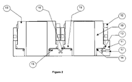
- FIG. 2 is a full section of FIG. 1 view showing internal porting and external porting of the unibody hydraulic nut assembly.
- FIG. 3 is a partial section detail view showing the unibody hydraulic nut with headed bolt installed.
- FIG. 4 is a partial side view of unibody hydraulic nut with headed bolt mated against unibody hydraulic nut.
- FIG. 5 is a partial top view of unibody hydraulic nut with headed bolt installed.
- FIG. 6 is a side view of unibody hydraulic nut showing installation of headed bolt by turning of a traditional socket against the mating hex.
- FIG. 7 is a full section view of FIG. 6 .
- FIG. 8 is a side view of unibody hydraulic nut with hydraulic pressure applied and the castellated locking collar lifting off the mating surface of the outer body.
- FIG. 9 is a full section view of FIG. 8 .
- FIG. 10 is a partial side view of the unibody hydraulic nut and castellated locking collar mated to the turning socket.
- FIG. 11 is a partial side view of turning tapered castellated socket as it engages with the locking collar of the unibody hydraulic nut.
- FIG. 11 a is a close up of engagement of tapered castellated socket with mating locking collar.
- FIG. 12 is a side view of prior art of traditional castellations on a locking collar.
- FIG. 13 is a side view of prior art of castellated turning sockets.
- FIG. 14 is a close up side view of FIG. 13 showing engagement with prior art castellated sockets.
- FIG. 15 is an isometric view of a typical application on unibody hydraulic nut on a completed deep water subsea pipe clamp according to the embodiment of the invention.
- FIG. 16 is a side view of FIG. 15 .
- FIG. 17 is an isometric view of a typical application of unibody hydraulic nut on a completed circular flange according the embodiment of the invention.
- FIG. 18 is a side view of FIG. 17 .
- FIG. 19 is an isometric view of a typical application of a unibody hydraulic nut where the flange is the unibody according to the embodiment of the invention.
- FIG. 20 is a side view of FIG. 19 .
- stud generally refers to stud, bolt, rod and other similarly shaped fasteners used in securing flanges assembly.
- a hydraulic nut for tensioning an assembly
- the unibody hydraulic nut also includes an external pressure port ( 17 ) extending through the outer body ( 11 ) of the hydraulic nut to the first pressure area ( 15 ) and adapted to be connected to an external hydraulic pressure source.
- seals ( 13 ) and ( 14 ) could be used. Elastomeric, elastic, metallic and/or non-metallic seals are all contemplated. Moreover, ring seals, C-shaped seals, U-shaped seals and seals of other shapes are also contemplated.
- FIGS. 3 to 6 A first embodiment of the present invention is best shown in FIGS. 3 to 6 . Its components consist of an outer unibody ( 11 ) that mates (surface 21 ) up against a flange assembly (see element 40 in FIG. 15 and element 41 in FIG. 17 ).
- a stud ( 20 ) or bolt with nut is inserted through the inner body ( 10 ) and corresponding flanges that are mating together.
- the stud ( 20 ) can be threaded into the mating flange or to a mating flange that has a through hole and wherein the stud ( 20 ) threads into a standard nut on the mating flange.
- the stud bolt ( 20 ) can have an integral hex head (see FIG. 4 ) to allow it to be turned into place using external means, such as a hex socket ( 23 ) (best shown in FIGS. 7 and 8 ).
- This load pushes down on the outer body ( 11 ) and mating flange whilst pushing up against the inner body ( 10 ) mated to the stud bolt ( 20 ).
- the applied pressure preferably uniformly and simultaneously provides an axial load to each of the stud bolts ( 20 ) in this assembly ( FIGS. 15 to 18 ). As the load is applied, the resultant forces will compress the flange assembly ( 40 , 41 ) whilst stretching the stud bolts ( 20 ).
- a castellated socket ( 31 ) is lowered over the locking collar ( 12 ) ( FIG. 11 ), the tapered castellations ( 30 ) of the socket allowing for easy insertion ( FIG. 11 a ) to mate the corresponding tapered castellation of the locking collar ( 12 ).
- Alternate turning means such as standard castellated socket ( 35 ) or locking collar with a tommy bar hole ( 32 ) could also be employed to turn the locking collar ( 12 ) on the mating threads of the inner body ( 10 ).
- the locking collar is turned down the threads on the inner body ( 10 ) until it mates and abuts against the outer body ( 11 ), effectively mechanically locking the clamping axial load. This process is done for all the locking collars ( 12 ) of the unibody hydraulic nut.
- a stud ( 20 ) with an integral head has been shown, the use of other types of studs ( 20 ) and other types of mating techniques between the studs ( 20 ) and the inner bodies ( 10 ) are also contemplated.
- the mating of the stud ( 20 ) with the inner body ( 10 ) could be effected with a normal threaded nut which is threaded down the stud until it abuts on and mates with the inner body ( 10 ).
- the inner wall of the inner body ( 10 ) could be threaded with threads matching those of the stud ( 20 ).
- the transmission of the axial load from the inner body ( 10 ) to the stud ( 20 ) would be done via the threads instead of via a nut or an integral head. Therefore, the present invention is not limited to a particular mating technique between the studs ( 20 ) and the inner bodies ( 10 ).
- the present invention is shown installed on a sub-sea clamp ( FIGS. 15 and 16 ).
- the outer body ( 11 ) mates with the sub-sea clamp ( 40 ).
- the axial forces generated by the invention draws the mating clamps ( 40 ) together, whilst the locking collar ( 12 ) maintains the stud bolt ( 20 ) clamping load.
- the outer body ( 11 ) is an elongated and generally straight body into which the inner bodies are preferably evenly disposed.
- the present invention is shown installed on the face of a circular flange ( FIGS. 17 and 18 ).
- the stud bolts ( 20 ) are inserted through the inner body ( 10 ) and connecting flanges ( 41 ) for threading on or attaching to mechanical locking means, in this case, mating nuts ( 42 ), on the opposite flange face.
- mechanical locking means in this case, mating nuts ( 42 ), on the opposite flange face.
- mechanical locking means could also be contemplated such as locking pin or even hydraulic nuts.
- the outer body ( 11 ) has the shape of a generally circular ring and the inner bodies ( 10 ) are preferably evenly disposed along the outer body ( 11 ).
- the flange ( 41 ) and the outer body ( 11 ) form a single outer body/flange component.
- the outer body ( 11 ) has been directly machined and integrated into the flange ( 41 ) to create a single physical component ( 11 ).
- the flange body is machined and internally ported in a similar way as for an external outer body ( FIG. 2 ).
- the inner bodies ( 10 ) are mated to the flange/outer body ( 11 ) in a similar fashion. Stud bolts ( 20 ) are inserted through the inner body, flange/outer body ( 11 ) and through the outer body of the mating flange ( 43 ) threading into corresponding nuts ( 42 ).
- outer body ( 11 ) of the present invention could be provided in a variety of shapes and sizes according to the specific needs of a specific flanges assembly.
Landscapes
- Engineering & Computer Science (AREA)
- General Engineering & Computer Science (AREA)
- Mechanical Engineering (AREA)
- Hand Tools For Fitting Together And Separating, Or Other Hand Tools (AREA)
- Connection Of Plates (AREA)
- Mutual Connection Of Rods And Tubes (AREA)
Priority Applications (5)
| Application Number | Priority Date | Filing Date | Title |
|---|---|---|---|
| US11/346,374 US7673849B2 (en) | 2006-02-03 | 2006-02-03 | Unibody hydraulic nut |
| CA2576644A CA2576644C (en) | 2006-02-03 | 2007-02-01 | Unibody hydraulic nut |
| BRPI0708023A BRPI0708023B1 (pt) | 2006-02-03 | 2007-02-02 | porca hidráulica de corpo único |
| EP07701747.3A EP1979630B1 (de) | 2006-02-03 | 2007-02-02 | Einteilige hydraulische mutter |
| PCT/CA2007/000148 WO2007087719A1 (en) | 2006-02-03 | 2007-02-02 | Unibody hydraulic nut |
Applications Claiming Priority (1)
| Application Number | Priority Date | Filing Date | Title |
|---|---|---|---|
| US11/346,374 US7673849B2 (en) | 2006-02-03 | 2006-02-03 | Unibody hydraulic nut |
Publications (2)
| Publication Number | Publication Date |
|---|---|
| US20070181861A1 US20070181861A1 (en) | 2007-08-09 |
| US7673849B2 true US7673849B2 (en) | 2010-03-09 |
Family
ID=38326362
Family Applications (1)
| Application Number | Title | Priority Date | Filing Date |
|---|---|---|---|
| US11/346,374 Active 2026-02-28 US7673849B2 (en) | 2006-02-03 | 2006-02-03 | Unibody hydraulic nut |
Country Status (5)
| Country | Link |
|---|---|
| US (1) | US7673849B2 (de) |
| EP (1) | EP1979630B1 (de) |
| BR (1) | BRPI0708023B1 (de) |
| CA (1) | CA2576644C (de) |
| WO (1) | WO2007087719A1 (de) |
Cited By (7)
| Publication number | Priority date | Publication date | Assignee | Title |
|---|---|---|---|---|
| US20090293418A1 (en) * | 2008-05-30 | 2009-12-03 | Gordon Britton | Foundation Bolt Tensioner |
| US8579572B1 (en) | 2012-07-23 | 2013-11-12 | Michael James Psimas | Load-relief washer assembly for threaded fasteners |
| US8579538B2 (en) | 2010-07-30 | 2013-11-12 | United Technologies Corporation | Turbine engine coupling stack |
| WO2014018443A1 (en) | 2012-07-23 | 2014-01-30 | Integra Services Technologies, Inc. | Load-relief washer assembly for threaded fasteners |
| US8832921B2 (en) | 2011-07-08 | 2014-09-16 | Metso Minerals Industries, Inc. | Locking nut assembly for a cone crusher |
| US20180062318A1 (en) * | 2016-08-29 | 2018-03-01 | Nike, Inc. | Cord-securing mechanism |
| US11597043B2 (en) * | 2016-09-05 | 2023-03-07 | Designbanken As | Bolt tensioning assembly and method for tensioning of a bolt |
Families Citing this family (3)
| Publication number | Priority date | Publication date | Assignee | Title |
|---|---|---|---|---|
| US7673849B2 (en) * | 2006-02-03 | 2010-03-09 | Integra Technologies Limited | Unibody hydraulic nut |
| DE102012110267A1 (de) | 2012-10-26 | 2014-04-30 | Thyssenkrupp Resource Technologies Gmbh | Kreiselbrecher zur Zerkleinerung von Brechgut |
| CN104551627B (zh) * | 2013-10-12 | 2017-01-18 | 中交广州航道局有限公司 | 一种液压多轴法兰螺栓松紧装置的使用方法 |
Citations (12)
| Publication number | Priority date | Publication date | Assignee | Title |
|---|---|---|---|---|
| US3199564A (en) * | 1964-02-17 | 1965-08-10 | Standard Pressed Steel Co | Castellated nut |
| US3287999A (en) * | 1963-11-27 | 1966-11-29 | Rheinstahl Huettenwerke Ag | Apparatus for facilitating the application and removal of nuts or the like |
| US4182215A (en) | 1978-05-30 | 1980-01-08 | Terra Tek, Inc. | Failsafe hydraulic prestressing nut |
| US4224843A (en) * | 1977-12-23 | 1980-09-30 | Kloeckner Werke Ag | Tensioning device for simultaneously tensioning a plurality of bolts |
| US4249718A (en) | 1978-04-18 | 1981-02-10 | Hydra-Tight Limited | Bolt tensioning device |
| US4773146A (en) | 1985-03-06 | 1988-09-27 | Pilgrim Engineering Developments, Ltd. | Multi-stud tensioners |
| US5046906A (en) | 1987-09-29 | 1991-09-10 | Bucknell John W | Force applicators |
| US5330159A (en) * | 1992-01-20 | 1994-07-19 | Westfalia Becorit Industrietechnik Gmbh | Apparatus for automatically inserting and removing screw-threaded elements into and from tapped bores |
| US5527015A (en) * | 1993-02-05 | 1996-06-18 | Hydra-Tight Limited | Hydraulic tensioning device |
| US6065737A (en) | 1997-12-09 | 2000-05-23 | Hydra-Tight Limited | Tensioning device |
| CA2496933A1 (en) | 2004-02-19 | 2005-08-19 | Integra Technologies Limited | Hydraulic nut and method of use thereof |
| US20070181861A1 (en) * | 2006-02-03 | 2007-08-09 | Gordon Britton | Unibody hydraulic nut |
Family Cites Families (3)
| Publication number | Priority date | Publication date | Assignee | Title |
|---|---|---|---|---|
| US3162071A (en) * | 1961-05-08 | 1964-12-22 | Biach Ind | Tensioning apparatus |
| GB2247928B (en) * | 1990-05-30 | 1993-07-14 | Hydra Tight Ltd | Bolt tensioning devices |
| DE10226961A1 (de) * | 2002-06-17 | 2004-01-08 | As Tech Industrie- Und Spannhydraulik Gmbh | Hydraulische Spannvorrichtung und deren Verwendung |
-
2006
- 2006-02-03 US US11/346,374 patent/US7673849B2/en active Active
-
2007
- 2007-02-01 CA CA2576644A patent/CA2576644C/en active Active
- 2007-02-02 WO PCT/CA2007/000148 patent/WO2007087719A1/en active Application Filing
- 2007-02-02 BR BRPI0708023A patent/BRPI0708023B1/pt active IP Right Grant
- 2007-02-02 EP EP07701747.3A patent/EP1979630B1/de active Active
Patent Citations (12)
| Publication number | Priority date | Publication date | Assignee | Title |
|---|---|---|---|---|
| US3287999A (en) * | 1963-11-27 | 1966-11-29 | Rheinstahl Huettenwerke Ag | Apparatus for facilitating the application and removal of nuts or the like |
| US3199564A (en) * | 1964-02-17 | 1965-08-10 | Standard Pressed Steel Co | Castellated nut |
| US4224843A (en) * | 1977-12-23 | 1980-09-30 | Kloeckner Werke Ag | Tensioning device for simultaneously tensioning a plurality of bolts |
| US4249718A (en) | 1978-04-18 | 1981-02-10 | Hydra-Tight Limited | Bolt tensioning device |
| US4182215A (en) | 1978-05-30 | 1980-01-08 | Terra Tek, Inc. | Failsafe hydraulic prestressing nut |
| US4773146A (en) | 1985-03-06 | 1988-09-27 | Pilgrim Engineering Developments, Ltd. | Multi-stud tensioners |
| US5046906A (en) | 1987-09-29 | 1991-09-10 | Bucknell John W | Force applicators |
| US5330159A (en) * | 1992-01-20 | 1994-07-19 | Westfalia Becorit Industrietechnik Gmbh | Apparatus for automatically inserting and removing screw-threaded elements into and from tapped bores |
| US5527015A (en) * | 1993-02-05 | 1996-06-18 | Hydra-Tight Limited | Hydraulic tensioning device |
| US6065737A (en) | 1997-12-09 | 2000-05-23 | Hydra-Tight Limited | Tensioning device |
| CA2496933A1 (en) | 2004-02-19 | 2005-08-19 | Integra Technologies Limited | Hydraulic nut and method of use thereof |
| US20070181861A1 (en) * | 2006-02-03 | 2007-08-09 | Gordon Britton | Unibody hydraulic nut |
Non-Patent Citations (3)
| Title |
|---|
| www.hydratight.com/english.information.114.html. |
| www.hydratight.com/english.information.213.html. |
| www.hydratight.com/english.information.322.html. |
Cited By (12)
| Publication number | Priority date | Publication date | Assignee | Title |
|---|---|---|---|---|
| US20090293418A1 (en) * | 2008-05-30 | 2009-12-03 | Gordon Britton | Foundation Bolt Tensioner |
| US8328482B2 (en) * | 2008-05-30 | 2012-12-11 | Integra Technologies Ltd. | Hydraulic foundation bolt tensioner |
| US8579538B2 (en) | 2010-07-30 | 2013-11-12 | United Technologies Corporation | Turbine engine coupling stack |
| US9371863B2 (en) | 2010-07-30 | 2016-06-21 | United Technologies Corporation | Turbine engine coupling stack |
| US8832921B2 (en) | 2011-07-08 | 2014-09-16 | Metso Minerals Industries, Inc. | Locking nut assembly for a cone crusher |
| US9157469B2 (en) | 2011-07-08 | 2015-10-13 | Metso Minerals Industries, Inc. | Locking nut assembly for a cone crusher |
| US8579572B1 (en) | 2012-07-23 | 2013-11-12 | Michael James Psimas | Load-relief washer assembly for threaded fasteners |
| WO2014018443A1 (en) | 2012-07-23 | 2014-01-30 | Integra Services Technologies, Inc. | Load-relief washer assembly for threaded fasteners |
| JP2016502626A (ja) * | 2012-07-23 | 2016-01-28 | インテグラ・サービシーズ・テクノロジーズ,インコーポレーテッド | ネジ付き締結具用の荷重逃がし座金組立体 |
| US20180062318A1 (en) * | 2016-08-29 | 2018-03-01 | Nike, Inc. | Cord-securing mechanism |
| US10862244B2 (en) * | 2016-08-29 | 2020-12-08 | Nike, Inc. | Cord-securing mechanism |
| US11597043B2 (en) * | 2016-09-05 | 2023-03-07 | Designbanken As | Bolt tensioning assembly and method for tensioning of a bolt |
Also Published As
| Publication number | Publication date |
|---|---|
| EP1979630A4 (de) | 2010-05-19 |
| EP1979630A1 (de) | 2008-10-15 |
| WO2007087719A1 (en) | 2007-08-09 |
| BRPI0708023B1 (pt) | 2018-10-30 |
| CA2576644C (en) | 2014-12-02 |
| US20070181861A1 (en) | 2007-08-09 |
| CA2576644A1 (en) | 2007-08-03 |
| BRPI0708023A2 (pt) | 2011-05-17 |
| EP1979630B1 (de) | 2013-07-24 |
Similar Documents
| Publication | Publication Date | Title |
|---|---|---|
| US7673849B2 (en) | Unibody hydraulic nut | |
| US20220372972A1 (en) | Fluid end assembly | |
| US20200232450A9 (en) | Multi-Piece Fluid End | |
| US20230323873A1 (en) | Multi-piece fluid end | |
| US20110266795A1 (en) | Threaded union for tubulars used in high-pressure fluid applications | |
| US10697569B2 (en) | Fluid connector assembly and method of establishing a fluid connection | |
| US11292093B2 (en) | Multi-jack tensioners | |
| KR20070011630A (ko) | 탈·부착이 용이한 배관의 이음구 | |
| AU2018393082B2 (en) | Multiple chamber hydraulic multi-jack bolt tensioners | |
| NO20161399A1 (en) | Bolt, bolt tensioning assembly and method for tensioning of a bolt | |
| US4168852A (en) | Ring gasket retainer for flanged connectors | |
| CN107023724B (zh) | 密封连接装置 | |
| KR100914153B1 (ko) | 파이프연결압륜 어셈블리 | |
| NO340578B1 (no) | Paknings- og rørstyringsenhet for undervanns rørkopling | |
| CN211371562U (zh) | 自带张紧功能的螺栓及海管法兰连接结构 | |
| US10280946B2 (en) | Adapter for mounting a cylinder for a fluid powered linear actuator to a fluid channel | |
| RU2703583C1 (ru) | Фланцевый соединитель | |
| CN217327995U (zh) | 一种螺栓紧固装置 | |
| US11767941B2 (en) | Apparatus for hydrostatic testing using power from and ROV | |
| CA2496933A1 (en) | Hydraulic nut and method of use thereof | |
| RU88096U1 (ru) | Разъемное соединение | |
| WO2005080804A1 (en) | Hydraulic nut and method of use thereof |
Legal Events
| Date | Code | Title | Description |
|---|---|---|---|
| AS | Assignment |
Owner name: INTEGRA TECHNOLOGIES LTD.,CANADA Free format text: ASSIGNMENT OF ASSIGNORS INTEREST;ASSIGNORS:HUGHES, DAVID;BRITTON, GORDON;REEL/FRAME:017556/0525 Effective date: 20060330 Owner name: INTEGRA TECHNOLOGIES LTD., CANADA Free format text: ASSIGNMENT OF ASSIGNORS INTEREST;ASSIGNORS:HUGHES, DAVID;BRITTON, GORDON;REEL/FRAME:017556/0525 Effective date: 20060330 |
|
| STCF | Information on status: patent grant |
Free format text: PATENTED CASE |
|
| FPAY | Fee payment |
Year of fee payment: 4 |
|
| MAFP | Maintenance fee payment |
Free format text: PAYMENT OF MAINTENANCE FEE, 8TH YEAR, LARGE ENTITY (ORIGINAL EVENT CODE: M1552) Year of fee payment: 8 |
|
| MAFP | Maintenance fee payment |
Free format text: PAYMENT OF MAINTENANCE FEE, 12TH YEAR, LARGE ENTITY (ORIGINAL EVENT CODE: M1553); ENTITY STATUS OF PATENT OWNER: LARGE ENTITY Year of fee payment: 12 |
|
| AS | Assignment |
Owner name: NATIXIS, NEW YORK BRANCH, AS COLLATERAL AGENT, NEW YORK Free format text: SECURITY AGREEMENT SUPPLEMENT FOR INTELLECTUAL PROPERTY;ASSIGNORS:INTEGRA SERVICES TECHNOLOGIES, INC.;INTEGRA TECHNOLOGIES LIMITED;REEL/FRAME:062445/0180 Effective date: 20230106 |