US7673605B2 - Rocker arm and method of manufacturing same - Google Patents
Rocker arm and method of manufacturing same Download PDFInfo
- Publication number
- US7673605B2 US7673605B2 US11/700,110 US70011007A US7673605B2 US 7673605 B2 US7673605 B2 US 7673605B2 US 70011007 A US70011007 A US 70011007A US 7673605 B2 US7673605 B2 US 7673605B2
- Authority
- US
- United States
- Prior art keywords
- pair
- punch
- plate material
- rocker arm
- guide
- Prior art date
- Legal status (The legal status is an assumption and is not a legal conclusion. Google has not performed a legal analysis and makes no representation as to the accuracy of the status listed.)
- Expired - Fee Related, expires
Links
Images


Classifications
-
- F—MECHANICAL ENGINEERING; LIGHTING; HEATING; WEAPONS; BLASTING
- F01—MACHINES OR ENGINES IN GENERAL; ENGINE PLANTS IN GENERAL; STEAM ENGINES
- F01L—CYCLICALLY OPERATING VALVES FOR MACHINES OR ENGINES
- F01L1/00—Valve-gear or valve arrangements, e.g. lift-valve gear
- F01L1/12—Transmitting gear between valve drive and valve
- F01L1/18—Rocking arms or levers
- F01L1/185—Overhead end-pivot rocking arms
-
- B—PERFORMING OPERATIONS; TRANSPORTING
- B21—MECHANICAL METAL-WORKING WITHOUT ESSENTIALLY REMOVING MATERIAL; PUNCHING METAL
- B21K—MAKING FORGED OR PRESSED METAL PRODUCTS, e.g. HORSE-SHOES, RIVETS, BOLTS OR WHEELS
- B21K1/00—Making machine elements
- B21K1/20—Making machine elements valve parts
- B21K1/205—Making machine elements valve parts rocker arms
-
- F—MECHANICAL ENGINEERING; LIGHTING; HEATING; WEAPONS; BLASTING
- F01—MACHINES OR ENGINES IN GENERAL; ENGINE PLANTS IN GENERAL; STEAM ENGINES
- F01L—CYCLICALLY OPERATING VALVES FOR MACHINES OR ENGINES
- F01L1/00—Valve-gear or valve arrangements, e.g. lift-valve gear
- F01L1/12—Transmitting gear between valve drive and valve
- F01L1/18—Rocking arms or levers
- F01L1/181—Centre pivot rocking arms
-
- Y—GENERAL TAGGING OF NEW TECHNOLOGICAL DEVELOPMENTS; GENERAL TAGGING OF CROSS-SECTIONAL TECHNOLOGIES SPANNING OVER SEVERAL SECTIONS OF THE IPC; TECHNICAL SUBJECTS COVERED BY FORMER USPC CROSS-REFERENCE ART COLLECTIONS [XRACs] AND DIGESTS
- Y10—TECHNICAL SUBJECTS COVERED BY FORMER USPC
- Y10T—TECHNICAL SUBJECTS COVERED BY FORMER US CLASSIFICATION
- Y10T29/00—Metal working
- Y10T29/49—Method of mechanical manufacture
- Y10T29/49229—Prime mover or fluid pump making
- Y10T29/49295—Push rod or rocker arm making
-
- Y—GENERAL TAGGING OF NEW TECHNOLOGICAL DEVELOPMENTS; GENERAL TAGGING OF CROSS-SECTIONAL TECHNOLOGIES SPANNING OVER SEVERAL SECTIONS OF THE IPC; TECHNICAL SUBJECTS COVERED BY FORMER USPC CROSS-REFERENCE ART COLLECTIONS [XRACs] AND DIGESTS
- Y10—TECHNICAL SUBJECTS COVERED BY FORMER USPC
- Y10T—TECHNICAL SUBJECTS COVERED BY FORMER US CLASSIFICATION
- Y10T74/00—Machine element or mechanism
- Y10T74/20—Control lever and linkage systems
- Y10T74/20576—Elements
- Y10T74/20882—Rocker arms
Definitions
- This disclosure relates to a rocker arm for actuating a valve of an internal combustion engine, and a method of manufacturing the same.
- a depth of a predetermined amount or more is required for the guide groove so that the engagement with the valve stem does not disengage and the valve stem is not swayed by rocking of the rocker arm.
- the plate material is pressed in the thickness direction thereof to form a guide groove as described above, and when the required depth of the guide groove is large, in some cases the drawing by the press becomes tight and causes the plate material to break at the time of formation. To avoid this situation, it is necessary to use a special material that has sufficient malleability as a plate material, and this leads to increased costs.
- the present invention was completed based on the above-mentioned circumstances, and an object of this invention is to provide a low-cost rocker arm that can be simply manufactured as well as a method of manufacturing the same.
- the rocker arm according to the present invention is a cold-formed rocker arm of the cam follower type that is attached to a cylinder head of an internal combustion engine, has a guide groove that accepts a top edge of a valve stem of the internal combustion engine, and rocks to actuate a valve of the internal combustion engine.
- the manufacturing method executes a punching step that punches a plate material into a predetermined shape having a pair of side edges; a press step that forms an initial groove having an opposing pair of guide walls by depressing the punched plate material by a predetermined amount in the thickness direction thereof by pressing a punch against the plate material; and a sandwich pressure step that increases the height of the guide walls by applying sandwiching pressure to the pair of guide walls in a direction from the outside thereof to the inside using a sandwich pressure punch (the guide groove is defined between the pair of guide walls).
- the press amount in the thickness direction of the plate material can be reduced so that, even without using a special material, the plate material does not break at the time of pressing.
- FIG. 1 is a sectional view illustrating a valve gear of an internal combustion engine that applies the rocker arm according to one illustrative aspect
- FIG. 2 is an enlarged view of the principal parts shown in FIG. 1 ;
- FIG. 3 is a side view of the rocker arm shown in FIG. 2 ;
- FIG. 4 is a plan view of the rocker arm shown in FIG. 2 ;
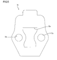
- FIG. 5 is a plan view of an punched material that is formed by punching a plate material to form an arm main unit;
- FIG. 6 is a plan view illustrating a state in which the side edges of a punched material are bent upward to form a roller housing portion;
- FIG. 7 is a plan view illustrating a state in which a receiving protrusion of a rocking support is further formed at one end;
- FIG. 8 is a sectional view illustrating the state of the other end before forming a guide groove in the arm main unit
- FIG. 9 is a sectional view illustrating a method that forms an initial groove at the other end of the arm main unit.
- FIG. 10 is a sectional view illustrating a method that forms a guide groove by applying sandwiching pressure to the initial groove.
- FIG. 1 is a view showing the upper part of an internal combustion engine cylinder head 1 .
- the cylinder head 1 is provided with a valve gear consisting of a pivot 2 of a rush adjuster, a camshaft 3 having a plurality of cams 31 , a valve 4 , a valve spring 5 and a rocker arm 6 .
- the rocker arm 6 is of a roller rocker arm type in which a roller 8 is provided in an arm main unit 7 , and the roller 8 comes in contact with the peripheral surface of the cams 31 of the camshaft 3 .
- a rocking support 71 that contacts against the top end of the pivot 2 is formed at one end of the arm main unit 7 , and at the other end thereof is formed a valve contacting part 73 that engages with the top end of a valve stem 41 of the valve 4 .
- valve 4 opens and closes each air intake and exhaust port of the internal combustion engine at a predetermined timing.
- the arm main unit 7 is formed as one piece by bending a metal plate by press working, and as shown in FIG. 3 , is formed to have a substantially U-shape cross section by bending toward the upper part (in the direction away from the cylinder head). Further, in this illustrative aspect, the arm main unit 7 is formed in a symmetric shape that takes a center line in the lengthwise direction when viewed from a planar perspective as a boundary.
- the center part of the arm main unit 7 forms a roller housing portion 72 for housing the above described roller 8 .
- an opening 72 a for allowing a part of the underside of the roller 8 to protrude externally is formed in the roller housing portion 72 .
- the roller 8 that is housed in the roller housing portion 72 is mounted in a freely rotatable condition by means of a support shaft 81 that passes through the pair of retainer walls 72 b.
- the two retainer walls 72 b that constitute the roller housing portion 72 are formed to have height dimensions that are substantially equal to the diameter of the roller 8 (in FIG.
- a first edge side of the arm main unit 7 constitutes the above described rocking support 71 , and at this area a swollen receiving protrusion 71 a is formed that is made in a dome shape by a drawing process so as to cover the top end of the pivot 2 in an engaged state.
- the aforementioned two retainer walls 72 b of the roller housing portion 72 extend linearly in the same space, and mutually parallel erect walls 73 a that constitute the valve contacting part 73 are formed at a first edge of the arm main unit 7 .
- the bottom ends of the erect walls 73 a are connected by a bridge part 73 c, and a mutually opposing pair of guide walls 73 d extend downward from the underside of the bridge part 73 c (see FIG. 3 ).
- a guide groove 73 b that is recessed in an upward direction is formed by the bridge part 73 c and the guide walls 73 d.
- the guide groove 73 b engages with the valve stem 41 such that the guide walls 73 d sandwich the top end thereof so that the valve stem 41 does not incline, and the valve 4 is actuated by the underside of the bridge part 73 c applying a pressing force to the surface at the top end of the valve stem 41 .
- the guide groove 73 b extends in the lengthwise direction of the arm main unit 7 , and the width dimension thereof (distance between the guide walls 73 d shown in FIG. 3 ) is designed to be roughly the same as the external diameter of the upper end of the valve stem 41 such that it mates therewith.
- the underside of the bridge part 73 c that is the contact surface with the valve stem 41 of the guide groove 73 b is formed in an arc shape so as to always contact against a substantially center part of the upper edge surface of the valve stem 41 , regardless of the rocking of the rocker arm 6 (see FIG. 2 ).
- a pair of side edges of the punched material 7 A that was punched into a predetermined shape are bent upward by press working to simultaneously form the pair of retainer walls 72 b of the roller housing portion 72 , the erect walls 73 a of the valve contacting part 73 and the bridge part 73 c (see FIG. 6 ).
- a first edge of the punched material 7 A is drawn upward by press working to form the receiving protrusion 71 a of the rocking support 71 and complete an intermediate member 7 B (see FIG. 7 ).
- the bridge part 73 c is pressed from below (in the thickness direction of the plate material) with a stripper punch 9 A to indent the bridge part 73 c by a predetermined amount in the upward direction and form an initial groove 73 e that is defined by a mutually opposing pair of walls 73 d (see FIG. 9 ).
- the depth of the initial groove 73 e is determined by the pressing force of the stripper punch 9 A, and the ultimately required depth of the guide groove 73 b is preferably about half, although the depth is not necessarily limited thereto.
- each erect wall 73 a is pressed using a pair of sandwich pressure punches 9 B to apply sandwiching pressure in the lateral direction to the walls 73 d of the initial groove 73 e.
- the material on the outside of the erect walls 73 a is pushed downward such that the walls 73 d increase in height to form guide walls 73 d of a predetermined height, and the guide groove 73 b is formed by that depression amount increasing further.
- the roller 8 is housed in the roller housing portion 72 and the support shaft 81 is passed through the shaft holes 72 c provided in the retainer walls 72 b to thereby attach that the roller 8 in a rotatable state between the retainer walls 72 b.
- the side edges of the plate material are bent upward to form the pair of retainer walls 72 b and the rotatable roller 8 is mounted between the retainer walls 72 b. It is therefore possible to manufacture the roller rocker arm 6 by only press working.
- the present invention is not limited to a roller rocker arm, and can also be applied to a rocker arm of a type that is attached to a rocker shaft and with respect to which a cam contacts an end thereof.
- the depth of an initial groove formed by pressing the plate material in the thickness direction can be suitably set in accordance with the plate thickness of the plate material, the kind of material, and the depth of the eventual guide groove.
Landscapes
- Engineering & Computer Science (AREA)
- Mechanical Engineering (AREA)
- General Engineering & Computer Science (AREA)
- Valve-Gear Or Valve Arrangements (AREA)
Abstract
Description
Claims (10)
Applications Claiming Priority (2)
| Application Number | Priority Date | Filing Date | Title |
|---|---|---|---|
| JP2006026174A JP2007205288A (en) | 2006-02-02 | 2006-02-02 | Rocker arm and manufacturing method thereof |
| JP2006-026174 | 2006-02-02 |
Publications (2)
| Publication Number | Publication Date |
|---|---|
| US20070175428A1 US20070175428A1 (en) | 2007-08-02 |
| US7673605B2 true US7673605B2 (en) | 2010-03-09 |
Family
ID=37964524
Family Applications (1)
| Application Number | Title | Priority Date | Filing Date |
|---|---|---|---|
| US11/700,110 Expired - Fee Related US7673605B2 (en) | 2006-02-02 | 2007-01-31 | Rocker arm and method of manufacturing same |
Country Status (4)
| Country | Link |
|---|---|
| US (1) | US7673605B2 (en) |
| EP (1) | EP1816319B1 (en) |
| JP (1) | JP2007205288A (en) |
| AT (1) | ATE539237T1 (en) |
Cited By (1)
| Publication number | Priority date | Publication date | Assignee | Title |
|---|---|---|---|---|
| US10337359B2 (en) * | 2015-04-17 | 2019-07-02 | Eaton Intelligent Power Limited | Rocker arm spring retainer |
Families Citing this family (2)
| Publication number | Priority date | Publication date | Assignee | Title |
|---|---|---|---|---|
| JP6387295B2 (en) * | 2014-12-17 | 2018-09-05 | 田中精密工業株式会社 | Method for manufacturing rocker arm |
| JP6769691B2 (en) | 2014-12-26 | 2020-10-14 | 株式会社オティックス | Rocker arm manufacturing method |
Citations (8)
| Publication number | Priority date | Publication date | Assignee | Title |
|---|---|---|---|---|
| US5720245A (en) | 1995-11-13 | 1998-02-24 | Sandco Automotive Limited | Finger follower arm |
| EP1057980A2 (en) | 1999-05-31 | 2000-12-06 | Koyo Seiko Co., Ltd. | Rocker arm and method of fabricating rocker arm body |
| JP2001191139A (en) | 1999-11-02 | 2001-07-17 | Nakanishi Metal Works Co Ltd | Rocker arm and method of manufacturing the same |
| JP2001198641A (en) | 2000-01-17 | 2001-07-24 | Otics Corp | Rocker arm and method for manufacturing the same |
| JP3207223B2 (en) | 1990-10-12 | 2001-09-10 | ヘンリー・マニュファクチャリング・ホールディング・カンパニー・インコーポレーテッド | Rocker arm |
| US6615635B2 (en) * | 2000-06-20 | 2003-09-09 | Ina Walzlager Schaeffler Ohg | Method of making a lever-type cam follower, and lever-type cam follower |
| US20040000277A1 (en) | 2002-06-26 | 2004-01-01 | Koyo Seiko Co., Ltd. | Manufacturing method of rocker arm |
| WO2005021183A1 (en) | 2003-08-27 | 2005-03-10 | Gen Tek Technologies Marketing, Inc. | A method and system for forming a cam-engaged rocker arm |
Family Cites Families (2)
| Publication number | Priority date | Publication date | Assignee | Title |
|---|---|---|---|---|
| JP3497373B2 (en) * | 1998-03-25 | 2004-02-16 | 中西金属工業株式会社 | Rocker arm and method of manufacturing the same |
| JP3934491B2 (en) * | 2002-06-26 | 2007-06-20 | 株式会社ジェイテクト | Rocker arm and manufacturing method thereof |
-
2006
- 2006-02-02 JP JP2006026174A patent/JP2007205288A/en active Pending
-
2007
- 2007-01-31 US US11/700,110 patent/US7673605B2/en not_active Expired - Fee Related
- 2007-01-31 EP EP07002139A patent/EP1816319B1/en not_active Not-in-force
- 2007-01-31 AT AT07002139T patent/ATE539237T1/en active
Patent Citations (10)
| Publication number | Priority date | Publication date | Assignee | Title |
|---|---|---|---|---|
| JP3207223B2 (en) | 1990-10-12 | 2001-09-10 | ヘンリー・マニュファクチャリング・ホールディング・カンパニー・インコーポレーテッド | Rocker arm |
| US5720245A (en) | 1995-11-13 | 1998-02-24 | Sandco Automotive Limited | Finger follower arm |
| EP1057980A2 (en) | 1999-05-31 | 2000-12-06 | Koyo Seiko Co., Ltd. | Rocker arm and method of fabricating rocker arm body |
| US6425361B1 (en) | 1999-05-31 | 2002-07-30 | Koyo Seiko Co., Ltd. | Rocker arm and method of fabricating rocker arm body |
| JP2001191139A (en) | 1999-11-02 | 2001-07-17 | Nakanishi Metal Works Co Ltd | Rocker arm and method of manufacturing the same |
| JP2001198641A (en) | 2000-01-17 | 2001-07-24 | Otics Corp | Rocker arm and method for manufacturing the same |
| US6615635B2 (en) * | 2000-06-20 | 2003-09-09 | Ina Walzlager Schaeffler Ohg | Method of making a lever-type cam follower, and lever-type cam follower |
| US20040000277A1 (en) | 2002-06-26 | 2004-01-01 | Koyo Seiko Co., Ltd. | Manufacturing method of rocker arm |
| EP1375830A1 (en) | 2002-06-26 | 2004-01-02 | Koyo Seiko Co., Ltd. | Rocker arm and its manufacturing method |
| WO2005021183A1 (en) | 2003-08-27 | 2005-03-10 | Gen Tek Technologies Marketing, Inc. | A method and system for forming a cam-engaged rocker arm |
Cited By (1)
| Publication number | Priority date | Publication date | Assignee | Title |
|---|---|---|---|---|
| US10337359B2 (en) * | 2015-04-17 | 2019-07-02 | Eaton Intelligent Power Limited | Rocker arm spring retainer |
Also Published As
| Publication number | Publication date |
|---|---|
| US20070175428A1 (en) | 2007-08-02 |
| ATE539237T1 (en) | 2012-01-15 |
| JP2007205288A (en) | 2007-08-16 |
| EP1816319A1 (en) | 2007-08-08 |
| EP1816319B1 (en) | 2011-12-28 |
Similar Documents
| Publication | Publication Date | Title |
|---|---|---|
| US20040261739A1 (en) | Rocker arm | |
| US20020005057A1 (en) | Method of manufacturing heat exchanging fin and die set for manufacturing the same | |
| WO2007023646A1 (en) | Manufacturing method for rocker arm | |
| US7673605B2 (en) | Rocker arm and method of manufacturing same | |
| US6425361B1 (en) | Rocker arm and method of fabricating rocker arm body | |
| JP2009138666A (en) | Valve operating device and rocker arm unit | |
| US7836860B2 (en) | Engine rocker arm | |
| US7788805B2 (en) | Method for manufacturing rocker arm | |
| US20160153320A1 (en) | Valve-actuating lever for reciprocating-piston internal combustion engines | |
| US20040000277A1 (en) | Manufacturing method of rocker arm | |
| US11143060B2 (en) | Rocker arm and method of manufacturing the same | |
| US10309263B2 (en) | Rocker arm and method of manufacturing the rocker arm | |
| JPH11287109A (en) | Rocker arm | |
| JPH07229407A (en) | Rocker arm | |
| JPH05179907A (en) | Plate roller rocker arm and manufacture thereof | |
| JP2001271614A (en) | Rocker arm and method for manufacturing the same | |
| JP3129977U (en) | Rocker arm | |
| JP4368518B2 (en) | Rocker arm manufacturing method | |
| CN213039340U (en) | Rocker arms and valve systems | |
| JP3805300B2 (en) | ROCKER ARM AND ROCKER ARM BODY MANUFACTURING METHOD | |
| JP3857639B2 (en) | Rocker arm | |
| CN107975394A (en) | Valve operating lever for reciprocating piston internal combustion engine and production thereof | |
| JPH0711919A (en) | Manufacture of rocker arm | |
| JPH07259512A (en) | Rocker arm | |
| JP2007170260A (en) | Rocker arm manufacturing method |
Legal Events
| Date | Code | Title | Description |
|---|---|---|---|
| AS | Assignment |
Owner name: OTICS CORPORATION,JAPAN Free format text: ASSIGNMENT OF ASSIGNORS INTEREST;ASSIGNORS:HIRAMATSU, NAOKI;TAKEUCHI, AKIRA;TODO, KIMIHIKO;AND OTHERS;SIGNING DATES FROM 20070119 TO 20070129;REEL/FRAME:018864/0439 Owner name: NAKANISHI METAL WORKS CO., LTD.,JAPAN Free format text: ASSIGNMENT OF ASSIGNORS INTEREST;ASSIGNORS:HIRAMATSU, NAOKI;TAKEUCHI, AKIRA;TODO, KIMIHIKO;AND OTHERS;SIGNING DATES FROM 20070119 TO 20070129;REEL/FRAME:018864/0439 Owner name: NAKANISHI METAL WORKS CO., LTD., JAPAN Free format text: ASSIGNMENT OF ASSIGNORS INTEREST;ASSIGNORS:HIRAMATSU, NAOKI;TAKEUCHI, AKIRA;TODO, KIMIHIKO;AND OTHERS;REEL/FRAME:018864/0439;SIGNING DATES FROM 20070119 TO 20070129 Owner name: OTICS CORPORATION, JAPAN Free format text: ASSIGNMENT OF ASSIGNORS INTEREST;ASSIGNORS:HIRAMATSU, NAOKI;TAKEUCHI, AKIRA;TODO, KIMIHIKO;AND OTHERS;REEL/FRAME:018864/0439;SIGNING DATES FROM 20070119 TO 20070129 |
|
| FPAY | Fee payment |
Year of fee payment: 4 |
|
| FEPP | Fee payment procedure |
Free format text: MAINTENANCE FEE REMINDER MAILED (ORIGINAL EVENT CODE: REM.) |
|
| LAPS | Lapse for failure to pay maintenance fees |
Free format text: PATENT EXPIRED FOR FAILURE TO PAY MAINTENANCE FEES (ORIGINAL EVENT CODE: EXP.) |
|
| STCH | Information on status: patent discontinuation |
Free format text: PATENT EXPIRED DUE TO NONPAYMENT OF MAINTENANCE FEES UNDER 37 CFR 1.362 |
|
| FP | Lapsed due to failure to pay maintenance fee |
Effective date: 20180309 |