US7671898B2 - Color-space transformation-matrix calculating method and image processing device - Google Patents
Color-space transformation-matrix calculating method and image processing device Download PDFInfo
- Publication number
- US7671898B2 US7671898B2 US11/340,628 US34062806A US7671898B2 US 7671898 B2 US7671898 B2 US 7671898B2 US 34062806 A US34062806 A US 34062806A US 7671898 B2 US7671898 B2 US 7671898B2
- Authority
- US
- United States
- Prior art keywords
- color
- space
- color space
- colors
- matrix
- Prior art date
- Legal status (The legal status is an assumption and is not a legal conclusion. Google has not performed a legal analysis and makes no representation as to the accuracy of the status listed.)
- Expired - Fee Related, expires
Links
- 239000011159 matrix material Substances 0.000 title claims abstract description 132
- 238000000034 method Methods 0.000 title claims abstract description 74
- 238000012545 processing Methods 0.000 title description 2
- 230000009466 transformation Effects 0.000 claims abstract description 100
- 230000006870 function Effects 0.000 claims abstract description 91
- 239000003086 colorant Substances 0.000 claims abstract description 84
- 238000006073 displacement reaction Methods 0.000 claims description 4
- 230000000737 periodic effect Effects 0.000 claims description 4
- 230000008569 process Effects 0.000 description 42
- 238000003384 imaging method Methods 0.000 description 9
- 238000010586 diagram Methods 0.000 description 5
- 238000004458 analytical method Methods 0.000 description 4
- 230000001131 transforming effect Effects 0.000 description 4
- 238000012897 Levenberg–Marquardt algorithm Methods 0.000 description 3
- 238000004364 calculation method Methods 0.000 description 3
- 238000005286 illumination Methods 0.000 description 3
- 238000012417 linear regression Methods 0.000 description 3
- 230000003287 optical effect Effects 0.000 description 3
- 238000007796 conventional method Methods 0.000 description 2
- 238000012937 correction Methods 0.000 description 2
- 230000000694 effects Effects 0.000 description 2
- 238000005457 optimization Methods 0.000 description 2
- 238000000926 separation method Methods 0.000 description 2
- 238000006243 chemical reaction Methods 0.000 description 1
- 230000000295 complement effect Effects 0.000 description 1
- 238000004519 manufacturing process Methods 0.000 description 1
- 238000005259 measurement Methods 0.000 description 1
- 238000012986 modification Methods 0.000 description 1
- 230000004048 modification Effects 0.000 description 1
- 238000001228 spectrum Methods 0.000 description 1
- 238000007619 statistical method Methods 0.000 description 1
- 238000011426 transformation method Methods 0.000 description 1
Images


Classifications
-
- H—ELECTRICITY
- H04—ELECTRIC COMMUNICATION TECHNIQUE
- H04N—PICTORIAL COMMUNICATION, e.g. TELEVISION
- H04N1/00—Scanning, transmission or reproduction of documents or the like, e.g. facsimile transmission; Details thereof
- H04N1/46—Colour picture communication systems
- H04N1/56—Processing of colour picture signals
- H04N1/60—Colour correction or control
- H04N1/603—Colour correction or control controlled by characteristics of the picture signal generator or the picture reproducer
- H04N1/6033—Colour correction or control controlled by characteristics of the picture signal generator or the picture reproducer using test pattern analysis
Definitions
- the present invention relates to a color adjusting method that optimizes color signals to improve the reproduction of color in an image, and an image processing device applying the method. More particularly, the invention relates to a color adjusting method using a color-space transformation-matrix.
- a color space of an image input system such as an image capturing apparatus
- a color space of an image output system such as a display and a printer.
- perceived color of a reproduced image when a captured image is displayed on a monitor, is generally different from that of an original subject. Further, the difference between the perceived colors also depends on the properties of each output device.
- color signals based on the sRGB standard which is a standard for the image input devices and image output devices, are generally used at present.
- the image input device outputs color signals after transforming the obtained RGB signals to signals based on the sRGB standard.
- precise color reproduction is performed as long as the image output devices are compatible with the sRGB standard.
- tints quite similar to the original object can be reproduced.
- a variety of methods for performing color adjustment are known in the art.
- the reproduced color can be converted to the original color by adjusting the spectrum characteristics of an optical filter, provided in an imaging system, to the sRGB standard or by transforming the RGB signals electronically by a matrix transformation.
- multiple linear regression analysis is used to improve the accuracy of color transformation methods that use a color space transformation matrix for electronic color adjustment.
- Multiple linear regression analysis optimizes the matrix elements of the color-space transformation-matrix by a statistical analysis which considers the relationship between the original color and the reproduced color as a cause and effect relationship. Namely, the matrix elements are obtained by optimizing these elements under the condition that the difference between the signal levels of the predicted reproduced colors, which is obtained by performing a provisional color space transformation matrix operation on the RGB signals from the imaging system, and the signal levels of the original colors, is below or equal to a permissible value.
- a method that uses multiple linear regression analysis to provide a matrix that transforms RGB signals to XYZ signals of a different calorimetric system is disclosed in the Japanese unexamined patent publication (KOKAI) No. 10-164381.
- the transformation from the color space of the image input system to the standard color space is generally a non-linear transformation, so that it is ineffective to sufficiently compensate for all of the color differences when the color compensation is carried out by a color space transformation matrix having constant element values, as in the conventional method.
- a color space transformation matrix calculating method calculates a color space transformation matrix which transforms colors in a first color space to colors in a second color space.
- the method optimizes a plurality of constant color-space transformation matrices, so that each of the constant color-space transformation matrices is adjusted to transform each standard color in the first color space to each goal color in the second color space, which correspond to each standard color.
- the method further calculates interpolation functions for each of the matrix elements of a color-space transformation matrix applied for the entire gamut of the first color space, based on the constant color-space transformation matrices.
- FIG. 1 schematically illustrates a system for calculating the color space transformation matrix of a first embodiment of the present invention
- FIG. 2 is a flow chart of a color-space transformation-matrix calculating process
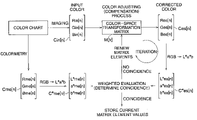
- FIG. 3 is a block diagram schematically showing processes that are carried out in the color space transformation matrix calculating process and the relationships between each of the color signals;
- FIG. 4 is a block diagram that illustrates a color-space transformation matrix optimizing process
- FIG. 5 is a flowchart of the color-space transformation matrix optimizing process
- FIG. 6 is a graph where the values of matrix elements m 11 [ 1 ] to m 11 [ 18 ] and a interpolation function m 11 ( ⁇ ) are shown;
- FIG. 7 is a flowchart of the signal processes carried out in the digital still camera when an image is captured
- FIG. 8 is a block diagram that schematically illustrates the flow of the signal processes.
- FIG. 9 is a graph that illustrates a solution of the interpolation function m 11 (a*, b*), which is indicated as the surface m 11 (a*, b*)-M 11 .
- FIG. 1 schematically illustrates a system for calculating the color space transformation matrix of a first embodiment of the present invention.
- the digital still camera 10 is employed as an example of an image input device, which is provided with an image signal processor relating to the invention.
- the digital still camera 10 generally includes an imaging optical system 12 , an imaging device, such as a CCD 14 , a digital signal processor 20 , and a memory 22 .
- An image detected by the imaging device 14 through the imaging optical system 12 is output as analog image signals, and subjected to analog signal processes.
- the analog image signals are then subjected to A/D conversion and fed to a digital signal processor 20 as digital image signals.
- a color separation process for example, generates predetermined color signals for each of the pixels in accordance with the digital image signals.
- the white balance adjusting process optimizes gains for each of the color signals in accordance with the standard white signal values.
- the color adjusting process transforms color signals of the first color space of the image input system to color signals of the second color space.
- the gradation adjusting process optimizes the gradation to counterbalance the gamma characteristics of the monitor 31 .
- RGB signals are employed as color signals of the first color space and standard RGB signals, which are standardized among image output devices, are employed as color signals of the second color space.
- sRGB signals that is an international standard for color reproduction which is standardized by IEC (International Electrotechnical Commission) are adopted as the standard RGB signals of the second color space. Namely, in the present embodiment, the RGB signals of the first color space, obtained by the photographing system, are transformed to the sRGB signals in the second color space.
- the digital signal processor 20 can be connected to external devices, such as a computer 30 , via an interface, so that the sRGB signals which have already been subjected to the color adjusting process, are output to image output devices, such as a monitor 31 (CRT or LCD) and/or a printer 32 connected to the computer 30 .
- external devices such as a computer 30
- image output devices such as a monitor 31 (CRT or LCD) and/or a printer 32 connected to the computer 30 .
- the color adjusting process is carried out by using a color-space transformation-matrix.
- the color-space transformation matrix is optimized so as to transform a plurality of standard colors represented in the first color space, which were imaged by the digital still camera 10 , to colors (goal colors) that are desired in the second color space.
- the color-space transformation-matrix is obtained by a color-space transformation-matrix calculating device or a matrix generator 34 , at the final stage of the manufacturing processes of the digital still camera 10 , and information relating to the color-space transformation-matrix is stored in a memory 22 of the digital still camera 10 .
- values of RGB signals of the goal colors in the second color space are preset in the matrix generator 34 and RGB signals of the first color space, which are obtained by imaging the standard colors, are input from the digital still camera 10 .
- the goal colors of the second color space are preset based on colorimetric values of the standard colors.
- the plurality of standard colors may be selected so as each of the colors is distributed uniformly over a uniform color space.
- a ready-made color chart checker available in the market may also be used (in consideration of ease of purchase and saving time and expense), for the calorimetric operations.
- the objective values (goal colors) that are set for calculating the color-space transformation-matrix are preset to the colorimetric values of the color standard colors.
- the objective values (goal colors) relating to particular standard colors may be preset to values which are modified from the calorimetric values.
- the Macbeth color checker 40 registered trademark is used as an example of the standard colors.
- the Macbeth color checker 40 has 24 color patches P 1 -P 24 as described in FIG. 1 (only part of the color patches are numbered for convenience), and eighteen color patches (P 1 -P 18 ), excluding six achromatic or gray scale color patches, are used as the above standard colors. Namely, the precise calorimetric values of the color patches P 1 -P 18 (which are obtained by a calorimeter) in the second color space are set as the goal colors.
- the color patches P 1 -P 18 as the standard colors are imaged by the digital still camera 10 under the same illumination conditions adopted in the color determination carried out by the colorimeter, and the RGB signals of the color patches (standard colors), obtained by the digital still camera 10 , will be the color signals of the standard colors in the first color space.
- the Macbeth color checker 40 Since the Macbeth color checker 40 is a ready-made item on the market, it is easy to obtain. Further, since the calorimetric values of the patches P 1 -P 24 are already known, it can save time and expense for the calorimetric operations. Further, the color chart is not restricted to the Macbeth color checker chart described in the present embodiment, but can also be a color chart of which color patches are distributed uniformly over uniform color space, such as the JIS standard color chart. Moreover, when a peculiar color chart that includes the specific colors (human skin color, blue sky color, and verdure color), which may appear frequently in photography, is prepared and used according to an object, these specific colors can be reproduced with fidelity.
- the matrix elements of the color-space transformation-matrix are constants so that all of the colors in the first color space are transformed to colors in the second color space by one linear transformation.
- correspondence between the first color space and the second color space cannot be represented by a linear transformation. Therefore, a color-space transformation using a color-space transformation-matrix with constant matrix elements is only an approximate transformation.
- the color-space transformation matrix is normally optimized in order to minimize the total error appearing over the gamut. In actual calculation of the optimization, the color-space transformation matrix is obtained by means of minimizing the total error generated in the color-space transformation performed on the plurality of standard colors.
- the transformation from the first color space to the second color space is not always sufficiently precise or minute. Therefore, in the present embodiment, the matrix elements of the color-space transformation matrix are considered as functions of independent variable(s) including coordinate(s) of an input color. Thereby, the color-space transformation matrix which is accommodated for each of the points (colors) in the first color space can be determined as to the coordinates of each point. Namely, in the present embodiment, the constant color-space transformation matrices (which have constant matrix elements) for each of the standard colors are obtained at first. Each of the constant color-space transformation matrices transforms the coordinates of corresponding standard color in the first color space to appropriate coordinates in the second color space.
- a color-space transformation matrix having variable elements, which can be adjusted to all colors including the standard colors, is then obtained based on the constant color-space transformation matrices that are optimized for each of the standard colors. Namely, an arbitrary color (coordinates) in the first color space is transformed to a color (coordinates) in the second color space by the color-space transformation matrix of which the variable matrix elements can be adjusted to an arbitrary color.
- Step S 105 the RGB signals (Rme[k], Gme[k], Bme[k]) of the goal colors Cme[k] are transformed to the L*a*b* signals (L*me[k], a*me[k], b*me[k]) of the CIE-L*a*b* color space (simply referred to as Lab color space in the following), which is a uniform color space.
- Step S 109 interpolation functions mij( ⁇ ) for the matrix elements of the variable color-space transformation matrix are obtained based on the constant matrix elements mij[k] of the color-space transformation matrices M[k], where the variable “ ⁇ ” represents the hue angle. Further, in Step S 111 , the information relating to the interpolation functions mij( ⁇ ) is fed to the digital still camera (the image input device) 10 and stored in the memory 22 , and thus the color-space transformation matrix calculating process of the present embodiment ends.
- FIG. 3 schematically illustrates the Lab color space in which a light source having a predetermined color temperature, is used for illumination.
- FIG. 4 is a block diagram that illustrates the color-space transformation matrix optimizing process and FIG. 5 is a flowchart thereof.
- Eq. (1) when denoting “Cin” as an input color, “M” as the color-space transformation matrix, and “Ces” as a corrected color.
- (Rin, Gin, Bin) and (Res, Ges, Bes) represent RGB signals (RGB coordinates) of the input color Cin and the corrected color Ces.
- the index of the color-space transformation matrices, which are subjected to the optimizing process is referred to as “k”
- the standard colors (input colors) Cin[n] are transformed to the corrected colors Ces[n] by the color-space transformation matrix M[k].
- the color-space transformation matrices M[k] are obtained by the damped least square method.
- Each of the color-space transformation matrices M[k] is calculated by using all of the standard colors (P 1 -P 18 ) while weighting the standard color P k .
- the optimization is not restricted to the damped least square method. Any optimizing methods known in the art and combinations thereof can also be used.
- the matrix operations are performed on the RGB signals.
- a uniform color space such as the Lab color space, is used to evaluate the coincidence between the colors.
- the RGB signals (Rme[n], Gme[n], Bme[n]) of the goal color Cme[n] and (Res[n], Ges[n]), Bes[n]) of the corrected color Ces[n] are transformed to the L*a*b* signals (L*me[n], a*me[n], b*me[n]) and (R*es[n], G*es[n], B*es[n]), which will be referred to as the Lab signals in the following, so that the coincidence between the colors is evaluated in the Lab color space.
- a uniform color space other than the Lab color space can also be used based upon requirements (precision or use), if the color space is associated with the color difference perceived by the human eye.
- a color space other than a uniform color space can also be used.
- standard colors may be selected from the selected color space so as the standard colors to be distributed uniformly over the selected color space.
- Eq. (5) is a formula for transforming the RGB signals to the XYZ signals.
- Eq. (6) is a formula for transforming the XYZ signals to the Lab signals. When evaluating the coincidence of colors, the RGB signals are transformed to the Lab signals via the XYZ signals.
- Step S 205 whether n ⁇ 18 is determined. When n ⁇ 18, the variable “n” is incremented by 1 and Step S 203 is repeated. On the other hand, when n ⁇ 18, Step S 207 is carried out.
- Step S 207 the coincidence between C*es[n] and C*me[n] is evaluated, so that whether C*es[n]) has converged to C*me[n] is determined. For example, the convergence is evaluated by determining whether a merit function ⁇ is below or equal to a predetermined threshold value.
- Step S 207 when it is determined, in Step S 207 , that C*es[n] has converged to C*me[n], the process proceeds to Step S 211 and thus the current values of mij[k] are determined as the optimum solution of the color-space transformation matrix M[k], and Step S 213 is carried out.
- Step S 213 whether k ⁇ 18 is determined. When k ⁇ 18, the optimum color-space transformation matrices for all of the standard colors (P n ) are obtained, so that this color-space transformation matrix optimizing process ends.
- Step S 213 when it is determined k ⁇ 18 in Step S 213 , the variable “k” is incremented by 1 and the process returns to Step S 201 . Namely, the optimizing process of the color-space transformation matrix M[k] for new value “k” is carried out.
- the merit function ⁇ is determined by Eq. (7), as an example.
- the value of the weight coefficients Wn[k] are extremely large values compared to the values of the other weight coefficients Wn[k] (n ⁇ k), so that color-space transformation matrix M[k] is optimized for the particular standard color (P k ).
- a term relating to the hue angle ⁇ may also be incorporated into the merit function and the term may be heavily weighted.
- the matrix elements mij[k] are obtained so that the merit function ⁇ is a minimum value for each of “k”.
- conditions for the merit function ⁇ to take the minimum value are given by nine equations represented by Eq. (8).
- the merit function ⁇ is nonlinear with respect to the matrix elements mij[k], so that in the present embodiment, the merit function ⁇ is linearized about the starting point m ij [k] 0 in terms of the matrix elements mij[k], where the starting point corresponds to provisional values of the matrix elements used in the calculation of Step S 203 .
- the linearized merit function ⁇ is obtained as Eq. (9).
- ⁇ ⁇ ⁇ m ⁇ [ k ] - ( A t ⁇ A + D ⁇ I ) - 1 ⁇ A t ⁇ ⁇ ⁇ ⁇ E ⁇ ⁇
- ⁇ ⁇ ⁇ m ⁇ [ k ] ( ⁇ ⁇ ⁇ m 11 ⁇ [ k ] ⁇ ⁇ ⁇ m 12 ⁇ [ k ] ⁇ ⁇ ⁇ ⁇ m 33 ⁇ [ k ] )
- ⁇ ⁇ ⁇ ⁇ E ( ⁇ ⁇ ⁇ E 1 ⁇ ⁇ ⁇ E 2 ⁇ ⁇ ⁇ E 18 )
- ⁇ A ( a 1 ⁇ _ ⁇ 1 a 1 ⁇ _ ⁇ 2 ... a 1 ⁇ _ ⁇ 9 a 2 ⁇ _ ⁇ 1 ... ... a 2 ⁇ _ ⁇ 9 ⁇ ⁇ ⁇ ⁇ a 18 ⁇ _ ⁇ 1 ... ... a
- ⁇ mij[k] represents displacement from the starting point mij[k] 0 , so that in Step S 209 , the values mij[k] 0 + ⁇ mij[k] replace the values of the starting point mij[k] 0 as new matrix elements mij[k]. Accordingly, the matrix elements mij[k] are renewed in turn, in Steps S 201 -S 209 , so that the values of the matrix elements mij[k] will converge to values that make the value of the merit function ⁇ below or equal to the predetermined threshold value, and in turn C*es[n] converges to C*me[n]n
- FIG. 6 is a graph in which the values of the matrix elements m 11 [ 1 ]-m 11 [ 18 ], which are obtained by the color-space transformation matrix optimizing process of Step S 107 , are plotted.
- the horizontal axis indicates the hue angle (radian) of a corresponding standard color (P k ) and the vertical axis indicates the value of the matrix elements.
- the interpolation is carried out by the interpolation function mij( ⁇ ), which includes only the hue angle ⁇ out of the coordinates of the Lab color space as an independent variable.
- the interpolation function m 11 ( ⁇ ) which is calculated from the values of the plotted matrix elements m 11 [ 1 ] to m 11 [ 18 ], is indicated as a solid line S 1 .
- the interpolation function mij( ⁇ ) of the present embodiment a function that is continuous, smooth and that satisfies a periodic boundary condition is chosen. Further, the interpolation function is chosen from functions in which the value of the first order derivative of the interpolation function mij( ⁇ ) are kept within a range that does not obstruct smooth gradation.
- the coefficients A1 ij to A5 ij are obtained by a method known in the art, including the least square method and the damped least square method.
- the color-space transformation matrices adjusted to each of the standard colors are obtained from the plurality of standard colors imaged by the image input device and the calorimetric value of the standard colors, and thereby the color-space transformation matrix optimized for arbitrary hue angle is obtained based on the color-space transformation matrices adjusted to each of the standard colors.
- the information relating to the interpolation function mij( ⁇ ) is stored in the memory 22 of the digital camera 10 in Step S 111 .
- the interpolation function mij( ⁇ ) the interpolation function itself including the coefficients A1 ij to A5 ij can be adopted.
- the Lab color space may be divided into smaller parts along the hue angle according to the required precision, so that the matrix elements mij representing each of the divisions may be obtained and stored in the memory 22 as a lookup table.
- the hue angle ⁇ of an input color is included in the range 2n ⁇ /N ⁇ 2(n+1) ⁇ /N, the color compensation is carried out by using the values of the matrix elements mij( ⁇ n).
- FIG. 7 is a flowchart of the signal processes carried out in the digital still camera when an image is captured. Further, FIG. 8 is a block diagram that schematically illustrates the flow of the signal processes.
- the above-discussed information relating to the interpolation function mij( ⁇ ) is stored in the memory 22 of the digital still camera 10 when the camera is shipped.
- the digital still camera 10 captures the image of an object in Step S 301
- the object image is obtained by the imaging device 14 as RGB signals, for example.
- Step S 303 Lab signals of the image are obtained from the RGB signals.
- Step S 305 the hue angle ⁇ p for each of the pixels “P” of the object image is calculated based on the Lab signals obtained in Step S 303 .
- Step S 307 the matrix elements mij for the hue angle ⁇ p are obtained. Namely, when the interpolation function mij( ⁇ ) including its coefficients are stored in the memory 22 , the values of the matrix elements mij for the hue angle ⁇ p are calculated. When the values of the interpolation function mij( ⁇ ) are stored in the memory 22 as data, the values of the matrix elements mij corresponding to the hue angle ⁇ p are selected from the lookup table, for example.
- Step S 309 the RGB signals of each of the pixels P of the object image are subjected to the color compensation process by using the matrix elements mij which are obtained for the hue angles ⁇ p of each of the pixels in Step S 307 .
- Step S 311 the RGB signals which are subjected to the color compensation are fed to the image output devices like the monitor 31 or the LCD on the digital still camera 10 .
- input colors can be precisely transformed to desired colors and the color reproduction is improved. These outcomes are achieved by regarding the matrix elements of the color-space transformation matrix as functions of coordinates of the color space and obtaining interpolation functions of the matrix elements over the entire gamut of the first color space, based on the plurality of standard colors.
- the a*-coordinate and the b*-coordinate of the Lab color space are adopted for the independent variables for the interpolation functions of the matrix elements mij.
- the interpolation function based on circular cylindrical coordinates is used, in the second embodiment, a continuous and smooth interpolation function based on orthogonal Cartesian coordinates is used. Note that, the other structures are the same as those in the first embodiment.
- the interpolation function mij (a*, b*) in the second embodiment is a polynomial of a* and b*, as described in the following.
- Mij ( a*, b* ) Mij+B 1 ij ⁇ a* 1 b* 0 +B 2 ij ⁇ a* 2 b* 0 +B 3 ij ⁇ a* 3 b* 0 +B 4 ij ⁇ a* 0 b* 1 +B 5 ij ⁇ a* 1 b* 1 . . . +B 11 ij ⁇ a* 3 b* 2 . . .
- Mij is the average of mij[k] ( ⁇ mij[k]/18).
- Each of the coefficients B1ij to B15ij of the interpolation functions are calculated by a numerical analysis including the least square method and damped least squared method, similar to the first embodiment. Further, the information relating to the obtained interpolation functions is stored in the memory 22 of the digital still camera 10 .
- the interpolation function itself including the coefficients B1ij to B15ij can be adopted.
- the Lab color space may be divided into smaller parts along the a*-axis and b*-axis, according to the required precision, so that the matrix elements mij representing each of the divisions may be obtained and stored in the memory 22 as a lookup table.
- the image input device is not restricted to the digital still camera 10 of the present embodiments, but it can also be any type of device, such as digital video camera, scanner, electronic endoscope, and the like.
- the matrix generator 34 is configured as a device external to the digital still camera 10 , however the matrix generating function may be incorporated into the digital still camera 10 .
- the software may be installed in a personal computer system and the image signals from the digital still camera 10 are subjected to the color correction processes in the personal computer system.
- the color space transformation matrix that adjusts the colors of the RGB signals obtained by the imaging system is based on the sRGB standard.
- the matrix calculating methods in the present embodiments are not restricted to the calculation of a matrix that is specific to this type of color correction.
- a color-space transformation matrix that interactively transforms color signals between different color spaces such as a transformation of RGB signals to XYZ signals or to CMYK signals for printing, and a transformation of CMY signals for complementary colors to RGB signals, may be calculated by the above-discussed method.
Landscapes
- Engineering & Computer Science (AREA)
- Multimedia (AREA)
- Signal Processing (AREA)
- Facsimile Image Signal Circuits (AREA)
- Color Image Communication Systems (AREA)
- Image Processing (AREA)
- Processing Of Color Television Signals (AREA)
Abstract
Description
where, a viewing angle of a standard observer is 2° and the standard CIE-D65 illumination is used.
L*=116×f(Y)−16
a*=500×{f(X)−f(Y)}
b*=200×{f(Y)−f(Z)} (6)
where
Here, Wn[k] represents weight coefficients set for each of the standard colors Pn (n=1-18) in the optimizing process of the color-space transformation matrix M[k]. Namely, in the present embodiment, the value of the weight coefficients Wn[k] are extremely large values compared to the values of the other weight coefficients Wn[k] (n≠k), so that color-space transformation matrix M[k] is optimized for the particular standard color (Pk). Note that, since human eyes are sensitive to a difference in hue, a term relating to the hue angle θ may also be incorporated into the merit function and the term may be heavily weighted.
mij(θ)=A1ij·sin(θ)+A2ij·cos(θ)+A3ij·sin(2θ)+A4ij·cos(2θ)+A5ij (10)
Mij(a*, b*)=Mij+B1ij·a* 1 b* 0 +B2ij·a* 2 b* 0 +B3ij·a* 3 b* 0 +B4ij·a* 0 b* 1 +B5ij·a* 1 b* 1 . . . +B11ij·a* 3 b* 2 . . . +B14ij·a* 2 b* 3 +B15ij·a* 3 b* 3
where, Mij is the average of mij[k] (Σmij[k]/18). In
Claims (20)
Applications Claiming Priority (2)
| Application Number | Priority Date | Filing Date | Title |
|---|---|---|---|
| JPP2005-021581 | 2005-01-28 | ||
| JP2005021581A JP4540492B2 (en) | 2005-01-28 | 2005-01-28 | Color conversion matrix calculation method and image signal processing apparatus |
Publications (2)
| Publication Number | Publication Date |
|---|---|
| US20060170942A1 US20060170942A1 (en) | 2006-08-03 |
| US7671898B2 true US7671898B2 (en) | 2010-03-02 |
Family
ID=36756185
Family Applications (1)
| Application Number | Title | Priority Date | Filing Date |
|---|---|---|---|
| US11/340,628 Expired - Fee Related US7671898B2 (en) | 2005-01-28 | 2006-01-27 | Color-space transformation-matrix calculating method and image processing device |
Country Status (2)
| Country | Link |
|---|---|
| US (1) | US7671898B2 (en) |
| JP (1) | JP4540492B2 (en) |
Cited By (3)
| Publication number | Priority date | Publication date | Assignee | Title |
|---|---|---|---|---|
| US20080079816A1 (en) * | 2006-09-29 | 2008-04-03 | Chang Shih Yen | Color matching method, and image capturing device and electronic apparatus using the same |
| US20110035308A1 (en) * | 2005-05-04 | 2011-02-10 | Rosenthal Collins Group, Llc | Method and system for providing automatic execution of gray box strategies for electronic trading |
| US20120033877A1 (en) * | 2009-02-19 | 2012-02-09 | Eads Deutschland Gmbh | Method for Entropy-Based Determination of Object Edge Curves |
Families Citing this family (20)
| Publication number | Priority date | Publication date | Assignee | Title |
|---|---|---|---|---|
| JP5124102B2 (en) * | 2006-05-16 | 2013-01-23 | Hoya株式会社 | Endoscope processor, image processing program, and endoscope system |
| WO2008108761A1 (en) * | 2007-03-08 | 2008-09-12 | Hewlett-Packard Development Company, L.P. | True color communication |
| JP4489800B2 (en) * | 2007-08-30 | 2010-06-23 | 株式会社スクウェア・エニックス | Image generating apparatus and method, program, and recording medium |
| JP4875578B2 (en) * | 2007-09-26 | 2012-02-15 | 富士フイルム株式会社 | Color conversion definition creation method, color conversion definition creation device, and endoscope system |
| JP5052286B2 (en) * | 2007-10-19 | 2012-10-17 | オリンパス株式会社 | Spectral characteristic correction apparatus, spectral characteristic correction method |
| JP5090146B2 (en) | 2007-12-06 | 2012-12-05 | オリンパス株式会社 | Color conversion coefficient calculation device, color conversion coefficient calculation program, and color conversion coefficient calculation method |
| JP5271631B2 (en) * | 2008-08-07 | 2013-08-21 | Hoya株式会社 | Image processing unit, imaging device, composite image creation program |
| US8395831B2 (en) * | 2008-12-22 | 2013-03-12 | Ricoh Production Print Solutions LLC | Color conversion with toner/ink limitations |
| KR101075773B1 (en) * | 2009-01-15 | 2011-10-25 | 인하대학교 산학협력단 | Calibrating method for white balance |
| JP2010213746A (en) * | 2009-03-13 | 2010-09-30 | Fujifilm Corp | Endoscopic image processing device and method and program |
| JP5545008B2 (en) * | 2010-04-26 | 2014-07-09 | 富士通株式会社 | Color interpolation apparatus and color interpolation program |
| US8643742B2 (en) * | 2010-10-15 | 2014-02-04 | Cisco Technology, Inc. | Crosstalk filter in a digital image processing pipeline |
| JP6288943B2 (en) | 2013-05-20 | 2018-03-07 | 三星ディスプレイ株式會社Samsung Display Co.,Ltd. | Video display device |
| JP6690860B2 (en) * | 2014-12-25 | 2020-04-28 | ビジオトゥルー アイブイエス | Method for quasi-linear transformation that is three-dimensional, maintains the hue plane and is differentiable for color correction |
| CN107615760B (en) * | 2015-05-20 | 2021-03-12 | 索尼公司 | Image processing apparatus, image processing method, imaging element, and imaging apparatus |
| JP6825441B2 (en) * | 2017-03-23 | 2021-02-03 | コニカミノルタ株式会社 | Information processing equipment, image forming equipment and programs |
| US11350070B2 (en) * | 2018-06-04 | 2022-05-31 | Michael Scott Brown | Systems, methods and computer programs for colorimetric mapping |
| US11457189B2 (en) * | 2019-06-20 | 2022-09-27 | Samsung Electronics Co., Ltd. | Device for and method of correcting white balance of image |
| CN114067003A (en) * | 2020-07-31 | 2022-02-18 | 北京小米移动软件有限公司 | Color gamut conversion method and device, electronic equipment and storage medium |
| CN112329588B (en) * | 2020-10-30 | 2024-01-05 | 中海石油(中国)有限公司 | Pipeline fault detection method based on Faster R-CNN |
Citations (17)
| Publication number | Priority date | Publication date | Assignee | Title |
|---|---|---|---|---|
| JPH0524403A (en) | 1991-06-26 | 1993-02-02 | Osaka Gas Co Ltd | Magnetically attractive wheel |
| JPH08275007A (en) | 1995-03-29 | 1996-10-18 | Konica Corp | Color correction device |
| JPH10164381A (en) | 1996-11-29 | 1998-06-19 | Fuji Photo Film Co Ltd | Color conversion method |
| JP2000125141A (en) | 1998-10-12 | 2000-04-28 | Fuji Xerox Co Ltd | Color transformation device |
| US6278533B1 (en) | 1996-11-29 | 2001-08-21 | Fuji Photo Film Co., Ltd. | Method of processing image signal |
| JP2001359114A (en) | 2000-06-09 | 2001-12-26 | Fuji Photo Film Co Ltd | Image input device using solid-state image pickup element and image input method, and recording medium for recording program for the method |
| US6400843B1 (en) * | 1999-04-22 | 2002-06-04 | Seiko Epson Corporation | Color image reproduction with accurate inside-gamut colors and enhanced outside-gamut colors |
| US20030038954A1 (en) * | 1999-11-18 | 2003-02-27 | Fujitsu Limited | Color coordinate transformation table generation method, color coordinate transformation table generation apparatus, and storage medium on which a color coordinate transformation table generation program is recorded |
| US20030058466A1 (en) * | 2001-09-21 | 2003-03-27 | Nikon Corporation | Signal processing unit |
| US20040145590A1 (en) * | 2003-01-29 | 2004-07-29 | Yi-Sheng Yu | Plasma display panel with color space transformation device |
| US20050018226A1 (en) * | 2003-07-25 | 2005-01-27 | Pentax Corporation | Color-space transformation-matrix calculating system and calculating method |
| US20050046883A1 (en) | 2003-08-29 | 2005-03-03 | Pentax Corporation | Color-space transformation-matrix calculating system and calculating method |
| US7098965B2 (en) * | 2001-12-12 | 2006-08-29 | Samsung Electronics Co., Ltd. | Digital video signal processing system and method |
| US7148996B2 (en) * | 1997-06-19 | 2006-12-12 | Mediatek Inc. | Multi-spectral image compression with bounded loss |
| US20070247532A1 (en) * | 2006-04-21 | 2007-10-25 | Megachips Corporation | Image processing apparatus |
| US7382379B1 (en) * | 1997-06-27 | 2008-06-03 | Eastman Kodak Company | Arrangement for mapping colors between imaging systems and method thereof |
| US7436996B2 (en) * | 2001-06-07 | 2008-10-14 | Genoa Color Technologies Ltd | Device, system and method of data conversion for wide gamut displays |
Family Cites Families (1)
| Publication number | Priority date | Publication date | Assignee | Title |
|---|---|---|---|---|
| JPH05244403A (en) * | 1992-02-26 | 1993-09-21 | Brother Ind Ltd | Masking coefficient decision device |
-
2005
- 2005-01-28 JP JP2005021581A patent/JP4540492B2/en not_active Expired - Fee Related
-
2006
- 2006-01-27 US US11/340,628 patent/US7671898B2/en not_active Expired - Fee Related
Patent Citations (19)
| Publication number | Priority date | Publication date | Assignee | Title |
|---|---|---|---|---|
| JPH0524403A (en) | 1991-06-26 | 1993-02-02 | Osaka Gas Co Ltd | Magnetically attractive wheel |
| JPH08275007A (en) | 1995-03-29 | 1996-10-18 | Konica Corp | Color correction device |
| JPH10164381A (en) | 1996-11-29 | 1998-06-19 | Fuji Photo Film Co Ltd | Color conversion method |
| US6278533B1 (en) | 1996-11-29 | 2001-08-21 | Fuji Photo Film Co., Ltd. | Method of processing image signal |
| US7148996B2 (en) * | 1997-06-19 | 2006-12-12 | Mediatek Inc. | Multi-spectral image compression with bounded loss |
| US7382379B1 (en) * | 1997-06-27 | 2008-06-03 | Eastman Kodak Company | Arrangement for mapping colors between imaging systems and method thereof |
| JP2000125141A (en) | 1998-10-12 | 2000-04-28 | Fuji Xerox Co Ltd | Color transformation device |
| US6400843B1 (en) * | 1999-04-22 | 2002-06-04 | Seiko Epson Corporation | Color image reproduction with accurate inside-gamut colors and enhanced outside-gamut colors |
| US20030038954A1 (en) * | 1999-11-18 | 2003-02-27 | Fujitsu Limited | Color coordinate transformation table generation method, color coordinate transformation table generation apparatus, and storage medium on which a color coordinate transformation table generation program is recorded |
| US20020012463A1 (en) | 2000-06-09 | 2002-01-31 | Fuji Photo Film Co., Ltd. | Apparatus and method for acquiring images using a solid-state image sensor and recording medium having recorded thereon a program for executing the method |
| JP2001359114A (en) | 2000-06-09 | 2001-12-26 | Fuji Photo Film Co Ltd | Image input device using solid-state image pickup element and image input method, and recording medium for recording program for the method |
| US7436996B2 (en) * | 2001-06-07 | 2008-10-14 | Genoa Color Technologies Ltd | Device, system and method of data conversion for wide gamut displays |
| US20030058466A1 (en) * | 2001-09-21 | 2003-03-27 | Nikon Corporation | Signal processing unit |
| JP2003101803A (en) | 2001-09-21 | 2003-04-04 | Nikon Corp | Signal processor |
| US7098965B2 (en) * | 2001-12-12 | 2006-08-29 | Samsung Electronics Co., Ltd. | Digital video signal processing system and method |
| US20040145590A1 (en) * | 2003-01-29 | 2004-07-29 | Yi-Sheng Yu | Plasma display panel with color space transformation device |
| US20050018226A1 (en) * | 2003-07-25 | 2005-01-27 | Pentax Corporation | Color-space transformation-matrix calculating system and calculating method |
| US20050046883A1 (en) | 2003-08-29 | 2005-03-03 | Pentax Corporation | Color-space transformation-matrix calculating system and calculating method |
| US20070247532A1 (en) * | 2006-04-21 | 2007-10-25 | Megachips Corporation | Image processing apparatus |
Non-Patent Citations (6)
| Title |
|---|
| English Language Abstract of JP 10-164381, Nov. 29, 1996. |
| English language Abstract of JP 2000-125141, Apr. 28, 2000. |
| English language Abstract of JP 2001-359114, Dec. 26, 2001. |
| English language Abstract of JP 2003-101803, Apr. 4, 2003. |
| English language Abstract of JP 5-24403, Sep. 21, 1993. |
| English language Abstract of JP 8-275007, Oct. 18, 1996. |
Cited By (5)
| Publication number | Priority date | Publication date | Assignee | Title |
|---|---|---|---|---|
| US20110035308A1 (en) * | 2005-05-04 | 2011-02-10 | Rosenthal Collins Group, Llc | Method and system for providing automatic execution of gray box strategies for electronic trading |
| US20080079816A1 (en) * | 2006-09-29 | 2008-04-03 | Chang Shih Yen | Color matching method, and image capturing device and electronic apparatus using the same |
| US7860307B2 (en) * | 2006-09-29 | 2010-12-28 | Sony Taiwan Limited | Color matching method, and image capturing device and electronic apparatus using the same |
| US20120033877A1 (en) * | 2009-02-19 | 2012-02-09 | Eads Deutschland Gmbh | Method for Entropy-Based Determination of Object Edge Curves |
| US8682067B2 (en) * | 2009-02-19 | 2014-03-25 | Eads Deutschland Gmbh | Method for entropy-based determination of object edge curves |
Also Published As
| Publication number | Publication date |
|---|---|
| JP2006211369A (en) | 2006-08-10 |
| JP4540492B2 (en) | 2010-09-08 |
| US20060170942A1 (en) | 2006-08-03 |
Similar Documents
| Publication | Publication Date | Title |
|---|---|---|
| US7671898B2 (en) | Color-space transformation-matrix calculating method and image processing device | |
| Balasubramanian | Device characterization | |
| US7586642B2 (en) | Color-space transformation-matrix calculating system and calculating method | |
| US5323249A (en) | Method for reproducing color images having one color gamut with a device having a different color gamut | |
| DE69915225T2 (en) | Image processing apparatus and image processing method | |
| US20030133138A1 (en) | Image processing method and apparatus | |
| US20050046883A1 (en) | Color-space transformation-matrix calculating system and calculating method | |
| US7586640B2 (en) | Signal processing unit | |
| JP2000333033A (en) | Method and device for compensation conversion and recording medium | |
| JPH11317883A (en) | Re-proofreading conversion method of color picture reproducing system, its device and its medium | |
| KR20050098949A (en) | Image processing device, method, and program | |
| US6757010B2 (en) | Method and system for calibrating color correction instructions between color correction devices | |
| US6744920B1 (en) | Method, apparatus, and recording medium for processing image data to obtain color-balance adjusted image data based on white-balance adjusted image data | |
| US7652806B2 (en) | Optimal node placement for multi-dimensional profile luts for arbitrary media and halftones using parameterized minimization | |
| JP2004312748A (en) | Method of generating balanced digital color image having minimum color error | |
| EP1441506A2 (en) | State-space based modeling of pixel elements of a dynamically varying color marking device | |
| JPH11317882A (en) | System for reproducing color picture, color converting method its device and its medium | |
| JPH09231353A (en) | Color picture processing system | |
| JP2005045446A (en) | Color conversion matrix calculation method and color correction method | |
| US8325199B2 (en) | Image processing apparatus and computer readable medium storing program | |
| US20060082843A1 (en) | Method and system for calibration and characterization of joint nonlinear and linear transformations for a color input or output device | |
| EP1223765A2 (en) | Processing film images for digital cinema | |
| JP4633806B2 (en) | Color correction techniques for color profiles | |
| US8086033B2 (en) | Device, method, and program storage medium for color conversion, device, method, and program storage medium for color conversion coefficient generation | |
| JP4300780B2 (en) | Color conversion coefficient creation method, color conversion coefficient creation apparatus, program, and storage medium |
Legal Events
| Date | Code | Title | Description |
|---|---|---|---|
| AS | Assignment |
Owner name: PENTAX CORPORATION,JAPAN Free format text: ASSIGNMENT OF ASSIGNORS INTEREST;ASSIGNOR:CHIBA, TORU;REEL/FRAME:017511/0847 Effective date: 20060126 Owner name: PENTAX CORPORATION, JAPAN Free format text: ASSIGNMENT OF ASSIGNORS INTEREST;ASSIGNOR:CHIBA, TORU;REEL/FRAME:017511/0847 Effective date: 20060126 |
|
| AS | Assignment |
Owner name: HOYA CORPORATION, JAPAN Free format text: MERGER;ASSIGNOR:PENTAX CORPORATION;REEL/FRAME:023760/0387 Effective date: 20080331 Owner name: HOYA CORPORATION,JAPAN Free format text: MERGER;ASSIGNOR:PENTAX CORPORATION;REEL/FRAME:023760/0387 Effective date: 20080331 |
|
| STCF | Information on status: patent grant |
Free format text: PATENTED CASE |
|
| FPAY | Fee payment |
Year of fee payment: 4 |
|
| FPAY | Fee payment |
Year of fee payment: 8 |
|
| FEPP | Fee payment procedure |
Free format text: MAINTENANCE FEE REMINDER MAILED (ORIGINAL EVENT CODE: REM.); ENTITY STATUS OF PATENT OWNER: LARGE ENTITY |
|
| LAPS | Lapse for failure to pay maintenance fees |
Free format text: PATENT EXPIRED FOR FAILURE TO PAY MAINTENANCE FEES (ORIGINAL EVENT CODE: EXP.); ENTITY STATUS OF PATENT OWNER: LARGE ENTITY |
|
| STCH | Information on status: patent discontinuation |
Free format text: PATENT EXPIRED DUE TO NONPAYMENT OF MAINTENANCE FEES UNDER 37 CFR 1.362 |
|
| FP | Lapsed due to failure to pay maintenance fee |
Effective date: 20220302 |