US7658564B2 - Palm rest with detachable assembly mechanism - Google Patents
Palm rest with detachable assembly mechanism Download PDFInfo
- Publication number
- US7658564B2 US7658564B2 US11/442,112 US44211206A US7658564B2 US 7658564 B2 US7658564 B2 US 7658564B2 US 44211206 A US44211206 A US 44211206A US 7658564 B2 US7658564 B2 US 7658564B2
- Authority
- US
- United States
- Prior art keywords
- palm rest
- assembly mechanism
- joint arm
- keyboard
- detachable assembly
- Prior art date
- Legal status (The legal status is an assumption and is not a legal conclusion. Google has not performed a legal analysis and makes no representation as to the accuracy of the status listed.)
- Active, expires
Links
Images


Classifications
-
- G—PHYSICS
- G06—COMPUTING OR CALCULATING; COUNTING
- G06F—ELECTRIC DIGITAL DATA PROCESSING
- G06F3/00—Input arrangements for transferring data to be processed into a form capable of being handled by the computer; Output arrangements for transferring data from processing unit to output unit, e.g. interface arrangements
- G06F3/01—Input arrangements or combined input and output arrangements for interaction between user and computer
- G06F3/02—Input arrangements using manually operated switches, e.g. using keyboards or dials
- G06F3/0202—Constructional details or processes of manufacture of the input device
Definitions
- the present invention relates to a palm rest with a detachable assembly mechanism, and particularly to a palm rest that utilizes a detachable assembly mechanism that attaches to a keyboard.
- palm rests are used to prevent the user's palm from being suspended in mid air while typing by keyboard for ergonomic purposes.
- the palm rest in prior art usually uses a pair of fastening members in order to attach the palm rest to a keyboard.
- the fastening members clip onto a pair of clipping slots formed on the keyboard, and the fastening members usually protrude outside the palm rest and cannot be retracted. Some fastening members protrude beyond the side of the palm rest, while some fastening members protrude beyond the bottom of the palm rest.
- Such a design directly affects packaging and transportation. For example, it creates many cavities in the package, wasting much space. The total occupied space of the palm rest is therefore increased, which reduces the capacity of a container and increases transportation costs.
- the present invention proposes a palm rest that can be assembled with keyboards and without the disadvantages of the prior art.
- the assembly mechanism of the palm rest is detachable. Furthermore the assembly mechanism is also foldable so that it can be packaged more conveniently and is extendable for installation and use. Thereby, the assembly mechanism of the palm rest of the present invention is designed to overcome the troublesomeness of the conventional palm rest for keyboards.
- the present invention provides a palm rest with a detachable assembly mechanism.
- the palm rest has at least one assembly mechanism for assembling the palm rest to a keyboard.
- the palm rest includes a shell, and at least one assembly mechanism.
- the shell forms a concave portion.
- the assembly mechanisms are accommodated in the concave portion of the shell.
- Each of the assembly mechanisms includes a joint arm.
- the joint arm has a first end and a second end. The first end is pivotally mounted to the palm rest, so that the joint arm is rotatable relative to the palm rest and is received in the concave portion.
- the palm rest has a second end that clips onto the keyboard.
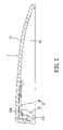
- FIG. 1 is a cross-sectional view of a palm rest after it has been folded for packaging of the present invention
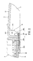
- FIG. 2 is a cross-sectional view of a palm rest assembled with a keyboard in an extended condition for installation of the present invention
- FIG. 3 is a perspective bottom view of a palm rest before assembly with a keyboard of the present invention
- FIG. 4 is a perspective bottom view of a palm rest after assembly with a keyboard of the present invention.
- FIG. 5 is a partial magnified view of a palm rest according to FIG. 2 of the present invention.
- FIGS. 1 and 2 are cross-sectional views of a palm rest having been folded and received, and assembled with a keyboard in an extended condition.
- the palm rest 1 of the present invention can be assembled with a keyboard 3 that is shown partially in FIG. 2 .
- a keyboard user's palm therefore would not be suspended midair thereby fulfilling the present invention's ergonomic aim.
- the palm rest 1 includes a shell 10 .
- the shell 10 forms a concave portion 11 that is concaved from its bottom surface.
- At least one detachable assembly mechanism 2 could be received in the concave portion 11 .
- the assembly mechanisms 2 are used to attach the palm rest 1 to the keyboard 3 .
- Each of the assembly mechanisms 2 include a base 21 and a joint arm 22 connecting with the base 21 .
- the base 21 is formed in the concave portion 11 of the shell 10 .
- One end of the joint arm 22 (hereinafter, designated as the first end) is pivotably mounted within the base 21 .
- the joint arm 22 therefore is rotatable and is received in the shell 10 , as shown in FIG. 1 .
- the joint arm 22 can be rotated to extend to the other end outside (hereinafter, designated as the second end) the shell 10 to attach to the keyboard 3 , as shown in FIG. 2 .
- FIGS. 3 and 4 are perspective bottom views of a palm rest before and after it has been attached to a keyboard of the present invention.
- the base 21 of the assembly mechanism 2 includes two symmetrical, parallel walls 211 that extend from the shell 10 of the palm rest 1 toward the concave portion 11 .
- the joint arm 22 includes a first end 221 , a second end 222 , and a curved portion 223 connecting the first end to the second end.
- the first end 221 is mounted pivotably between the two walls 211 of the base 21 , so that the joint arm 22 can be rotated or turned over along a pivoting portion.
- a plurality of elastic buckling fingers 224 extend out from the second end 222 .
- Each of the elastic buckling fingers 224 forms a buckling part 225 , as shown in FIG. 3 .
- the palm rest 1 can be therefore elastically clipped onto the keyboard 3 .
- the base 21 forms at least one fixing bump 213 on one of the walls 211 .
- the base 21 can also be formed with a pair of fixing bumps 213 , which respectively protruding inwardly from the wall 211 .
- the fixing bumps 213 position the joint arm 22 in the palm rest 1 .
- the keyboard 3 has at least one combining member 32 at its bottom surface 31 .
- the combining member 32 includes a pair of guiding rails 321 and a buckle depression 323 formed between the pair of guiding rails 321 .
- Each of the guiding rails 321 is formed with a sliding slot 322 opposite to each other.
- the second end 222 of the joint arm 22 is disposed in the sliding slot 322 of the pair of guiding rails 321 in a slidable manner.
- the elastic buckling fingers 224 of the second end 222 are clipped into the buckle depressions 323 of the keyboard 3 at the predetermined fixed positions, as shown in FIGS. 2 , 3 , and 5 .
- the combining members 32 can be separated from the keyboard 3 .
- the combining members 32 are adhered or screwed to the bottom surface of the keyboard 3 . Therefore, the present invention can be utilized to all keyboards which lack palm rests.
- the buckle depression 323 of the combining member 32 is formed at the bottom surface of the keyboard 3 , and is shaped like a “W” when viewed side on.
- the buckle depression 323 has two adjacent valleys 324 , 325 .
- the buckling part 225 of the elastic buckling finger 224 will slide into the valley 324 at an outer side when being assembled, and then slide into the valley 325 at an inner side when it is pushed.
- Such a structure not only ensures that the palm rest is attached to the predetermined position, but also provides a larger and therefore more convenient detaching space when detaching the palm rest 1 from the keyboard 3 .
- the present invention utilizes the assembly mechanism 2 which can be rotated along its pivoting portion, so that it can be folded and received in the concave portion 11 of the palm rest 1 for packaging convenience, as shown in FIG. 1 . In other words, it reduces cavities in the packaged product and less space is wasted. The total space of the palm rest is not enlarged, so that transportation costs are not increased. Moreover, the assembly mechanism 2 extends outside the concave portion 11 of the palm rest 1 along its pivoting portion, as shown in FIG. 2 .
- the second end 222 of the assembly mechanism 2 can slide into the pair of guiding rails 321 , and the elastic buckling finger 224 of the second end 222 can be clipped in the buckle depression 323 of the keyboard 3 at the end point of the sliding stroke, such as can be seen in FIGS. 2 , 3 and 5 .
- the elastic buckling finger 224 can be smoothly released from the buckle depression 323 , and the second end 222 can be released from the guiding rails 321 .
- the palm rest 1 is thereby detached.
- the palm rest of the invention includes the following advantages:
- the assembly mechanism 2 of the palm rest 1 adopts a detachable structure, which includes the base 21 and the joint arm 22 combined in a pivotal way.
- the assembly mechanism 2 can therefore be retracted into the concave portion 11 when packaged, and can be extended outside the concave portion 11 when assembled with the combining member 32 of the keyboard 3 when being attached to the keyboard.
- the packaged product has few cavities thereby reducing the total size of the palm rest and minimizing transportation costs.
Landscapes
- Engineering & Computer Science (AREA)
- General Engineering & Computer Science (AREA)
- Theoretical Computer Science (AREA)
- Human Computer Interaction (AREA)
- Physics & Mathematics (AREA)
- General Physics & Mathematics (AREA)
- Input From Keyboards Or The Like (AREA)
Abstract
Description
Claims (9)
Priority Applications (1)
| Application Number | Priority Date | Filing Date | Title |
|---|---|---|---|
| US11/442,112 US7658564B2 (en) | 2006-05-30 | 2006-05-30 | Palm rest with detachable assembly mechanism |
Applications Claiming Priority (1)
| Application Number | Priority Date | Filing Date | Title |
|---|---|---|---|
| US11/442,112 US7658564B2 (en) | 2006-05-30 | 2006-05-30 | Palm rest with detachable assembly mechanism |
Publications (2)
| Publication Number | Publication Date |
|---|---|
| US20070280771A1 US20070280771A1 (en) | 2007-12-06 |
| US7658564B2 true US7658564B2 (en) | 2010-02-09 |
Family
ID=38790383
Family Applications (1)
| Application Number | Title | Priority Date | Filing Date |
|---|---|---|---|
| US11/442,112 Active 2027-12-13 US7658564B2 (en) | 2006-05-30 | 2006-05-30 | Palm rest with detachable assembly mechanism |
Country Status (1)
| Country | Link |
|---|---|
| US (1) | US7658564B2 (en) |
Citations (3)
| Publication number | Priority date | Publication date | Assignee | Title |
|---|---|---|---|---|
| US5826839A (en) * | 1997-02-12 | 1998-10-27 | Chen; Frank | Keyboard with wrist support |
| US20050121567A1 (en) * | 2003-11-13 | 2005-06-09 | Arturo Meuniot | Hinged stand with breakaway action |
| US20060168783A1 (en) * | 2005-01-31 | 2006-08-03 | Joseph Anscher | Dual locking buckle |
-
2006
- 2006-05-30 US US11/442,112 patent/US7658564B2/en active Active
Patent Citations (3)
| Publication number | Priority date | Publication date | Assignee | Title |
|---|---|---|---|---|
| US5826839A (en) * | 1997-02-12 | 1998-10-27 | Chen; Frank | Keyboard with wrist support |
| US20050121567A1 (en) * | 2003-11-13 | 2005-06-09 | Arturo Meuniot | Hinged stand with breakaway action |
| US20060168783A1 (en) * | 2005-01-31 | 2006-08-03 | Joseph Anscher | Dual locking buckle |
Also Published As
| Publication number | Publication date |
|---|---|
| US20070280771A1 (en) | 2007-12-06 |
Similar Documents
| Publication | Publication Date | Title |
|---|---|---|
| US9581291B2 (en) | Positioning grip for a mobile electronic device | |
| US7566043B2 (en) | Angle regulator and equipment with the angle regulator | |
| US7909624B2 (en) | Carabiner universal serial bus hub | |
| US20130140837A1 (en) | Portable computer holder with adjustable hand grip | |
| US8684139B2 (en) | Step stool | |
| US20120104185A1 (en) | Portable computer holder | |
| US20130161967A1 (en) | Holding device for a mobile electronic device | |
| US20080174557A1 (en) | Ergonomic mouse | |
| US20070169273A1 (en) | Inflatable pad assembly | |
| US20050078441A1 (en) | Palm-size game case | |
| US20080297490A1 (en) | Stylus for a touch-screen device | |
| US7385596B2 (en) | Stylus attachment structure for IT products | |
| US7658564B2 (en) | Palm rest with detachable assembly mechanism | |
| US20130048801A1 (en) | Low-Profile Stand | |
| US7428143B1 (en) | Tablet computer palette with extended bezel | |
| US6702496B1 (en) | Writing pen with a holder | |
| US20040256964A1 (en) | Stabilizer mechanism for computer related equipment | |
| CN105818725B (en) | A kind of inside door handle | |
| US20020083558A1 (en) | Clip device | |
| US7570248B2 (en) | Mouse having storable hook module | |
| KR100312578B1 (en) | Hand strap storage structure for portable terminal device | |
| US20110016650A1 (en) | Cleaning tool | |
| US7614815B1 (en) | Receiving bag held by a hook-type folder | |
| CN213041100U (en) | Police shield convenient to stack | |
| US6130944A (en) | Multi-position telephone unit |
Legal Events
| Date | Code | Title | Description |
|---|---|---|---|
| AS | Assignment |
Owner name: LITE-ON TECHNOLOGY CORPORATION, TAIWAN Free format text: ASSIGNMENT OF ASSIGNORS INTEREST;ASSIGNOR:DENG, YONG-TONG;REEL/FRAME:017943/0269 Effective date: 20060508 Owner name: LITE-ON TECHNOLOGY CORPORATION,TAIWAN Free format text: ASSIGNMENT OF ASSIGNORS INTEREST;ASSIGNOR:DENG, YONG-TONG;REEL/FRAME:017943/0269 Effective date: 20060508 |
|
| STCF | Information on status: patent grant |
Free format text: PATENTED CASE |
|
| FPAY | Fee payment |
Year of fee payment: 4 |
|
| FPAY | Fee payment |
Year of fee payment: 8 |
|
| MAFP | Maintenance fee payment |
Free format text: PAYMENT OF MAINTENANCE FEE, 12TH YEAR, LARGE ENTITY (ORIGINAL EVENT CODE: M1553); ENTITY STATUS OF PATENT OWNER: LARGE ENTITY Year of fee payment: 12 |