US765585A - Tobacco-stemming machine. - Google Patents
Tobacco-stemming machine. Download PDFInfo
- Publication number
- US765585A US765585A US19311704A US1904193117A US765585A US 765585 A US765585 A US 765585A US 19311704 A US19311704 A US 19311704A US 1904193117 A US1904193117 A US 1904193117A US 765585 A US765585 A US 765585A
- Authority
- US
- United States
- Prior art keywords
- cutters
- belts
- tobacco
- machine
- portions
- Prior art date
- Legal status (The legal status is an assumption and is not a legal conclusion. Google has not performed a legal analysis and makes no representation as to the accuracy of the status listed.)
- Expired - Lifetime
Links
Images


Classifications
-
- A—HUMAN NECESSITIES
- A24—TOBACCO; CIGARS; CIGARETTES; SIMULATED SMOKING DEVICES; SMOKERS' REQUISITES
- A24B—MANUFACTURE OR PREPARATION OF TOBACCO FOR SMOKING OR CHEWING; TOBACCO; SNUFF
- A24B5/00—Stripping tobacco; Treatment of stems or ribs
- A24B5/06—Stripping tobacco; Treatment of stems or ribs by stripping leaf-parts from the stem
Definitions
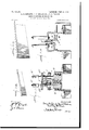
- Figure 1 is a side view of a leaf-stemming machine embodying the invention.
- Fig. 2 is a vertical longitudinal sectional view of the same.
- Fig. 3 is a detail view illustrating the appearance of the stem and leaf portion or strip after passing through the machine.
- Fig. 4 is a top plan view of the machine.
- Fig. 5 is a perspective view, drawn to an enlarged scale, of the adjustable feeding-plateand one of the lateral adjustable supports for the same.
- Fig. 6 is a similar view of the stemming-plate located beneath the rotary knives or cutters.
- Fig. 7 is a similar view,drawn to a smaller scale, showing the longitudinal roller-supporting bar or backbone of the machine.
- Fig. 1 is a side view of a leaf-stemming machine embodying the invention.
- Fig. 2 is a vertical longitudinal sectional view of the same.
- Fig. 3 is a detail view illustrating the appearance of the stem and leaf portion or strip after passing through the
- FIG. 8 is an enlarged top plan view of a portion of the machine, showing the feed-belts, the compressingrollers therefor, and the cutters and stem-cleaning brushes.
- Fig. 9 is a top plan view of the rotary cutters drawn to an enlarged scale.
- Figs. 9 and 9 are edge views of the two cutters.
- Fig.'10 is a side elevation of the portion of the machine shown in Fig. 8.
- Fig. 12 is a horizontal longitudinal section on line 12- 12 of Fig. 10.
- Fig. 13 is an enlarged perspective view, partly in section, showing the belts, the central roller-supporting bar or backbone, and one pair of compresssing-rollers and attached devices, the parts being separated and the shaft for said rollers being removed.
- Fig. 1A is a vertical transverse section on line 14c 14, Fig. 10.
- Fig. 23 is a vertical transverse sectional view on line 23 23 of Fig. 22.
- Fig. 24L is a top plan view of the rear portion of the machine shown in Fig. 22.
- Fig. 25 is an end elevation of the same.
- 26 is a detail view of a slightly-modified form of rotary cutter.
- A represents the main supporting-frame of the machine, carried upon suitable legs or standards a a and formed in any desired way to support the working parts of the mechanism.
- At the rear of the frame A are two vertical shafts b b, carrying large grooved driving -wheels B B at their upper ends and provided at their lower ends with miter-gears b, meshing with similar mitergears 0 on a driving-shaft C, provided witha band-pulley 0 for supplying power thereto and driving the grooved wheels B B the parts being so arranged that the wheels B B turn toward each other.
- a pair of feecling belts E E are placed on the wheels D and B in pairs, so as to have parallel contiguous portions extending longitudinally of the machine,and these belts are so arranged as to grip the butt-ends of the leaf-stems between them, and thus carry them from one end of the machine to the other.
- aseries of compressingrollers are employed, disposed vertically in pairs opposite to each other and provided with peripheral flanges, which hold the belts firmly together.
- rollers The construction of these rollers is well illus trated in Figs. 8, 10, 11, and 13.
- F represents a longitudinal supporting-bar supported above the center of the machine and provided with a series of apertures f to receive the studs which carry this compression-roller, said bar, which is termed sometimes the backbone, being shown detachedin Fig. 7
- Transverse studs f f are mounted in the apertures f, and upon each of these studs are placed two opposing compressing-rollers f f each provided with a bushing f", and each having a single peripheral fiangef on the outer side of the roller.
- Springs f f are placed on the stud f on the outer sides of the rollers and are held in place by collars f 6.
- vertical guides g 9 extend downward below the guides G G, leaving a narrow channel sufficiently wide for any stem to pass through.
- the rotary knives or cutters H H for assisting in removing the leaf portions from the stems and severing the lateral fibers of the leaves as the latter are drawn through the machine by the feed-belts E E.
- the cutters are mounted on substantially vertical axes and are arranged side by side, as shown, and are so arranged that they may separate sufficiently to permit a stem to enter and pass through between them.
- the cutters H H are mounted on the lower ends of two shafts it, each of which is mounted in bearings h it, secured to arms W71 connected to a sleeve 71, mounted on a shaft or stud secured to the main frame in any desired manner, the construction providing two laterally-swinging frames, which carry the cutters and permit them to move laterally toward and from each other.
- the knives are held together by a spring it, connected to each of the swinging frames, and are held from coming into contact with each other by stops formed in this case by set-screws 11 k carried by vertically-extending brackets h it, secured to the part of the frame which carries the swinging frames.
- the cutters H are provided with'serrations or teeth, as illustrated in Figs. 9, 9 and 9", preferably inclined to the axes of the cutters, as shown, and the cutters are so driven that they rotate toward each other and toward the front of the machine, as indicated by the arrows in these figures.
- Beneath the cutters is a horizontal plate I, (see Fig. 6,) having lateral attaching-flanges 2' 2', provided with slotted openings 7," a" to enable it to be secured 5 in position and adjusted longitudinally of the machine by means of suitable screws.
- the plate I is also provided with an angular recess 11 the apex of which is located below .a point midway between the cutters and slightly in advance of a line connecting their axes, as shown'in Fig. 12. During the operation of stemming the leaf portions pass below this plate and the plate serves to support the stem, which passes over it, and to guide it centrally between the cutters. (See Fig. 2.)
- a hopper K which extends forward beyond the front beltwheels D D and rearward of the cutter a corresponding distance and is provided with converging inclined bottom portions in is, leaving a discharge-aperture /c at the lowest point for the discharge of the leaf portions into a suitable receptacle.
- a vertically and longitudinally adjustable feedplate L supported therein, over which the leaves fed to the machine pass, and by regulating the angle of this plate the angle at which the leaves are held in the belts is determined, and by adjusting the plate to' ward or from the cutters the amount of the stem taken out of the leaves can be very accurately gaged.
- This plate is shown in detail in Fig.
- / M represents air-tubes connected to a common air-pipe M, communicating with a supply of compressed air (not shown) and which may be an air-compressor or storage-tank.
- Said air-tubes lead to nozzles N N, which are so placed as to direct blasts of compressed air against the leaf portions on each side of the stems at the point where the cutters are acting upon the stems.
- These jets of air assist in the separation of the leaf portions from the stems and also carry the leaf portions or strips downward as fast as they are removed from thestems and cause them to drop in the hopper K.
- the downward pressure of these air-blasts is exerted on the leaf just in front of the cutters, and while the leaf-body is partly supported on the plate L the stemming action continues.
- two round leather belts P P are shown, which are driven from a counter-shaft overhead (not shown) and engage suitable idle pulleys Q Q and R R and pulleys H H on the cutter-shafts and pulleys O O on the brushshafts'.
- the invention is in no wise limited, however, to this form of driving mechanism, as these moving parts can be driven in any other preferred or suitable manner.
- the manner of driving these parts is illustrated in Fig. 21, but will not be more particularly described, as it forms no part of the present invention.
- a slightly-modified form of the machine is shown, the modification consisting chiefly in a different mechanism for removing particles of the leaf which may adhere to the stem, which may be denominated stem-cleaning mechanism.
- the brushes O are dispensed with and the stems are first discharged from the carrying or feeding belts and then are passed longitudinally between two cleaning-belts provided with card-clothing, pins, or wires or other suitable devices.
- One of said belts is run at higher speed than the other, but having their adjacent portions moving in the same direction, and the action of the two belts removes all the portions of leaf from the stems, leaving them' perfectly clean.
- each belt is preferably made with a selvage on each edge free from teeth for a Widtlrof about half an inch, and longitudinal guides s s t t are provided for engaging the selvages and guiding the belts, so
- Adjustable belt-tightening devices are provided for eachbelt, as shown at S T, for keeping the belts taut.
- the lower belt is run at a moderate or slow speed by any preferred gearing.
- the main drivingshaft O is provided with a beveled gear 0 engaging a beveled gear u on an inclined shaft U, the other end of which is provided with a beveled gear a, engaging a similar gear zf 'on the shaft 25* of the rear lower belt-roller t.
- On the shaft t is a large gear-wheel t', which meshes with a pinion s" on the shaft 8* of the rear roller sof the upper belt,and thus drives the upper belt at a higher rate of speed than the lower belt.
- V represents a trough or guiding-chute which receives the stems as they are discharged from the feeding-belts and deposits thein uponthe lower cleaning-belt. (See Fig. 22.
- the stems and the particles of leaf removed therefrom will be discharged at the rear ends of the belts S and T, and as the stems are heavier than the leaf portions they will be thrown a considerable distance to the rear, while the scraps of leaf will be dropped almost vertically and may be caught in any suitable receptacle and disposed of in any preferred way.
- Fig. 26 is shown a modified form of rotary cutter H, in which the inclined cutting edges b are curved inwardly from top to bottom, so that when the two cutters come together around .a stem they will practically surround it.
- the edges 7e are preferably also inclined to the axis of the cutter; but this is not essential.
- a tobacco-stemming machine the combination with horizontally-disposed cutters having substantially vertical peripheral portions provided with cutting-surfaces, said cutters being arranged in the same horizontal plane, mechanism for driving said cutters toward each other, and means for applying a jet of air to the leaf portions on'each side of the stem adjacent to and in front of the meeting portions of said cutters, substantially as described.
- the combination with horizontally-disposed cutters having substantially vertical peripheral portions provided with cutting-surfaces, said cutters being'arranged in the same horizontal plane, mechanism for driving said cutters toward each other, and a horizontally-disposed feeding mechanism located above said cutters and having continuous portions extending from a point in front of said cutters to a point in rear of the same, substantially as described.
- the combination with horizontally-disposed cutters having substantially vertical peripheral portions provided with cutting-surfaces, said cutters being arranged in the same horizontal plane, mechanism for driving the cutters toward each other, whereby the stems are permitted to assume different angular positions with respect to the axes of the cutters while passing between the cutters, and mechanism permitting said cutters to yield away from each other to accommodate the varying diameters of the stems, substantially as described.
- a tobacco-stemming machine the combination with feeding devices for gripping the stems of the leaves and carrying them through the machine, of a pair of laterally-movable frames, a rotary cutter mounted in each frame, spring-actuated devices normally drawing said cutters and frames toward each other and adjustable devices for limiting the inward movement of said frames, substantially as described.
- a tobacco-stemming machine the combination with devices for gripping and feeding the stems of the leaves, of a pair of rotary cutters having substantially vertical axes arranged side by side and air-nozzles arranged on opposite sides of the travel of the leaves, and forward of said cutters, substantially as described.
- a tobacco -stemming machine the combination with the gripping and feeding devices, of a pair of cutters located adjacent to the travel thereof and having substantially vertical axes, a leaf guiding and supporting plate forward of said cutters, means for directing jets of air on the leaf adjacent to and forward of the points of operation of said cutters, and means for adjusting said plate toward and from the cutters, substantially as described.
- a tobacco-stemming machine the combination with the gripping and feeding devices, of a pair of cutters located adjacent to the travel thereof and having substantially vertical axes, a leaf guiding and supporting plate forward of said cutters, means for directing jets of air on the leaf adjacent to and forward of the points of operation of said'cutters, means for adjusting said plate toward and from the cutters, and means for adjusting said plate vertically, substantially as described.
- a horizontal supporting device provided with a series of transverse shafts, a series of vertically-disposed rollers mounted in pairs upon said shafts and engaging said belts on the upper faces of the same, said rollers having exterior flanges engaging the outer lateral faces of said belts, and springs engaging the outer faces of said rollers, substantially as described.
- the combination with the feeding mechanism and cutting mechanism, of stem-cleaning mechanism comprising two belts having their faces provided With cleaning projections, said belts being so arranged as to have adjacent parallel portions and means for driving said belts at different speeds, the said parallel portions moving in the same direction, substantially as described.
- the combination with feeding mechanism and mechanism for separating the leaf portions from the stems, of stem-cleaning mechanism comprising a pair of belts having adjacent parallel portions, and provided with cleaning projections, the lower belt being longer than the upper belt, means for depositing the stems from the feeding devices upon the said lower belt and means for driving one of said belts at higher speed than the other belt, substantially as described.
- a stem-cleaning mechanism comprising among its members a belt provided with cleaning projections and having a horiZontally-disposed portion, aco6perating device having a movable surface provided with cleaning projections located above the horizontally-disposed portion of said belt, means for driving said belt, and means for operating said cooperating device to cause its surface adjacent to said belt to travel in the same direction as and at a different rate of speed from said belt, substantially as described.
- a tobacco-stemming machine comprising among its members, two belts having their faces provided with cleaning projections, said belts having adjacent parallel portions, and means for driving said belts at different speeds, said parallel portions moving in the same direction, said guides engaging the adjacent portions of said belts and holding them out of-contact with each other, substantially as described.
- a stem-cleaningmechanism comprising among its members two belts having their faces provided with cleaning projections, said belts having adjacent parallel portions, and means for driving said belts at different speeds, said parallel portions moving in the same direction, said belts having lateral plain edges not provided with cleaning projections, and guides engaging the said plain edges of the adjacent portions of said belts and holding them out of contact with each other, substantially as described.
Description
- PATENTED JULY 19, 1904, "L. 1). LORBNTZ, J. a. BUCHANAN & A. 0. TRAVIS.
TOBACCO STBMMING MACHINE.
APPLIOATIOH FILED r213. 11. 1504. NOMODEL. 12snnms-s1mm 1.
. [NVEJVTORS No. 765,585. PATENTED JULY 19, 1904. L. 1). LORBNTZ, J. c. BUCHANAN & A. 0. TRAVIS.
TOBACCO STBMMING MACHINE.
APPLIGATION FILED FEB. 11. 1904.
12 SHEETS-SHEET 2.
HO MODEL.
[NVENTORS Attorney 0 No. 765,585. PATBNTED JULY 19, 1904. y
L. D. LORENTZ, J. C. BUCHANAN & A. 0. TRAVIS.
TOBACCO STEMMING MACHINE.
urmoumn rum) r113. 11, 1904.
N0 MODEL. 12 SHEETS-SHEET 3.
No. 765,585. PATENTED JULY 19, 1904. L. D. LORENTZ, J. O. BUCHANAN & A. 0. TRAVIS. TOBACCO STEMMING MACHINE.
APPLICATION FILED FEB. 11, 1904.
N0 MODEL. 12 SHEETS-SHEET 4.
f/VVENTORS BY 0.6M.
Attomeya No. 755,505. I PATENTED JULY 10, 1904, L. 0. LORENTZ, J. 0. 5005mm 0 A. 0. TRAVIS; TOBACCO STEMMING MACHINE.
APPLICATION FILED FEB.11. 1904.
NO MODEL. 0:; 12 SHEETFSHBBT 5.
NVENTOR PATENTED JULY 19, 1904.
L. D. LORENTZ, J. C. BUCHANAN & A. O. TRAVIS.
TOBACCO STEMMING MACHINE.
APPLICATION FILED FEB. 11. 1904.
12 SHEETS-SHEET 6.
L E D o M 0 N TOBACCO STEMMING MACHINE.
APPLIGATION FILED FEB. 11. 1904.
12 SHEETS-SHEET NO MODEL.-
No. 765,585. PATBNTED JULY 19, 1904. L. D. LORENTZ, J. G. BUCHANAN & A. O. TRAVIS.
TOBACCO STEMMING MACHINE.
APPLICATION FILED FEB. 11. 1904.
N0 MODEL. 12 BHEETSSHEE T 8.
N5. 765,585. PATENTED JULY 19, 1904. L. 1). LORENTZ, J. 0.. BUCHANAN 5 A. 0. TRAVISL TOBACCO STEMMING MACHINE.
\ APPLICATION FILED PEB.'11. 1904. 50 MODEL. 12 SHEET8-SHEET 9.
INVENTORS i -M55-5 69x22 5 No. 765,585. PATENTED JULY 19, 1904.
L. D. LORENTZJ. BUCHANAN & A. 0. TRAVIS.
TOBACCO STEMMING MACHINE. APPLICATION FILED FEB, 11. 190
12 SHEETS-SHBET '10.
no Mom-1L.
7 [ME T R-3 7/? 6, I Affomqvc No. 765,585. PATENTED JULY 19, 1904. L. D. LORENTZ, J. C. BUCHANAN & A. 0. TRAVIS.
TOBACCO STEMMING MACHINE.
APPLICATION FILED FEB. 11. 1904. v
12 SHEETS-SHEET 11.
N0 MODEL.
PATENTED JULY l9,- 1904.
L. D. LQRBNTZ, J. "O. BUCHANAN & A. 0. TRAVIS.
TOBACCO STEMMING MACHINE.
- APPLICATION FILED PBB.11. 190*}. I
12 SHEBTSSHEET 12.
N0 MODEL.
| miiiiiigh Hall! l [III I lllllllll UNITED STATES Patented. July 19,1904.
PATENT- OFFICE.
LORENZO D. LORENTZ, JAMES C. BUCHANAN, AND ASHER O. TRAVIS, OF WASHINGTON, DISTRICT OF COLUMBIA, ASSIGNORS TO THE PNEUMATIC TOBACCO STEMMER COMPANY, OF WASHINGTON, DIS- TRICT OF COLUMBIA, A CORPORATION OF VIRGINIA.
TOBACCO-STEIVHVIING MACHINE.
SPECIFICATION forming part of Letters Patent No. 765,585, dated July 19, 1904.
Application filed February 11, 1904. Serial No. 193,117. (No model.) I
To all whom it may concern.-
Be it known that we, LORENZO D. LOREN'IZ, JAMES C. BUCHANAN, and ASHER O. TRAVIS, citizens of the United States, residing at Washington, in the District of Columbia, have invented certain new and useful Improvements in Tobacco-Stemming Machines; and we do hereby declare the following to be a full, clear, and exact description of the invention, such as will enable others skilled in the art to which it appertains to make and use the same.
This invention consists in the novel features hereinafter described, reference being had to the accompanying drawings, which illustrate one form in which it has been contemplated to embody the invention, and said invention is fully disclosed in the following description and claims.
Referring to the said drawings, Figure 1 is a side view of a leaf-stemming machine embodying the invention. Fig. 2 is a vertical longitudinal sectional view of the same. Fig. 3 is a detail view illustrating the appearance of the stem and leaf portion or strip after passing through the machine. Fig. 4: is a top plan view of the machine. Fig. 5 is a perspective view, drawn to an enlarged scale, of the adjustable feeding-plateand one of the lateral adjustable supports for the same. Fig. 6 is a similar view of the stemming-plate located beneath the rotary knives or cutters. Fig. 7 is a similar view,drawn to a smaller scale, showing the longitudinal roller-supporting bar or backbone of the machine. Fig. 8 is an enlarged top plan view of a portion of the machine, showing the feed-belts, the compressingrollers therefor, and the cutters and stem-cleaning brushes. Fig. 9 is a top plan view of the rotary cutters drawn to an enlarged scale. Figs. 9 and 9 are edge views of the two cutters. Fig.'10 is a side elevation of the portion of the machine shown in Fig. 8. Fig. 11
is a vertical longitudinal sectional view of the same. Fig. 12 is a horizontal longitudinal section on line 12- 12 of Fig. 10. Fig. 13 is an enlarged perspective view, partly in section, showing the belts, the central roller-supporting bar or backbone, and one pair of compresssing-rollers and attached devices, the parts being separated and the shaft for said rollers being removed. Fig. 1A is a vertical transverse section on line 14c 14, Fig. 10. Fig.
cal section of a slightly-modified form of the machine, showing a modified form of stemcleaning mechanism. Fig. 23 is a vertical transverse sectional view on line 23 23 of Fig. 22. Fig. 24L is a top plan view of the rear portion of the machine shown in Fig. 22. Fig. 25 is an end elevation of the same. Fig.
26 is a detail view of a slightly-modified form of rotary cutter.
In the drawings,A represents the main supporting-frame of the machine, carried upon suitable legs or standards a a and formed in any desired way to support the working parts of the mechanism. At the rear of the frame A are two vertical shafts b b, carrying large grooved driving -wheels B B at their upper ends and provided at their lower ends with miter-gears b, meshing with similar mitergears 0 on a driving-shaft C, provided witha band-pulley 0 for supplying power thereto and driving the grooved wheels B B the parts being so arranged that the wheels B B turn toward each other.
At the front of the machine are two similar grooved wheels D D, mounted to turn loosely on studs (Z CZ, supported by sliding plates (Z engaging the main frame and provided with screws (Z for adjusting the studs and wheels D D toward or from the wheels B B, one of said screws 6Z being shown in Fig. 1. A pair of feecling belts E E are placed on the wheels D and B in pairs, so as to have parallel contiguous portions extending longitudinally of the machine,and these belts are so arranged as to grip the butt-ends of the leaf-stems between them, and thus carry them from one end of the machine to the other.
In order to hold the parallel contiguous portions of the belts together and enable them to firmly grip the butt-end of each leaf-stem presented to the front wheels D D, so as to prevent the stems from pulling out of the belts, aseries of compressingrollers are employed, disposed vertically in pairs opposite to each other and provided with peripheral flanges, which hold the belts firmly together.
The construction of these rollers is well illus trated in Figs. 8, 10, 11, and 13.
F represents a longitudinal supporting-bar supported above the center of the machine and provided with a series of apertures f to receive the studs which carry this compression-roller, said bar, which is termed sometimes the backbone, being shown detachedin Fig. 7 Transverse studs f f are mounted in the apertures f, and upon each of these studs are placed two opposing compressing-rollers f f each provided with a bushing f", and each having a single peripheral fiangef on the outer side of the roller. Springs f f are placed on the stud f on the outer sides of the rollers and are held in place by collars f 6.
and nuts f all as clearly showninthe figures above referred to, particularly in Fig. 13, in which the parts are shown detached. It will be seen that the belts E E will be held between the flanges f of the rollers, which can yield laterally against the springs to permit a stem to pass between them in the belts,
through the machines, vertical guides g 9 extend downward below the guides G G, leaving a narrow channel sufficiently wide for any stem to pass through.
In front of the first pair of rollers and prac-' tically beneath the same are located the rotary knives or cutters H H for assisting in removing the leaf portions from the stems and severing the lateral fibers of the leaves as the latter are drawn through the machine by the feed-belts E E. The cutters are mounted on substantially vertical axes and are arranged side by side, as shown, and are so arranged that they may separate sufficiently to permit a stem to enter and pass through between them. To this end the cutters H H are mounted on the lower ends of two shafts it, each of which is mounted in bearings h it, secured to arms W71 connected to a sleeve 71, mounted on a shaft or stud secured to the main frame in any desired manner, the construction providing two laterally-swinging frames, which carry the cutters and permit them to move laterally toward and from each other. The knives are held together by a spring it, connected to each of the swinging frames, and are held from coming into contact with each other by stops formed in this case by set-screws 11 k carried by vertically-extending brackets h it, secured to the part of the frame which carries the swinging frames. By adjusting these screws if 71. the normal distance between the cutters can be accurately adjusted, as shown in Fig. 8.
The cutters H are provided with'serrations or teeth, as illustrated in Figs. 9, 9 and 9", preferably inclined to the axes of the cutters, as shown, and the cutters are so driven that they rotate toward each other and toward the front of the machine, as indicated by the arrows in these figures. Beneath the cutters is a horizontal plate I, (see Fig. 6,) having lateral attaching-flanges 2' 2', provided with slotted openings 7," a" to enable it to be secured 5 in position and adjusted longitudinally of the machine by means of suitable screws. The plate I is also provided with an angular recess 11 the apex of which is located below .a point midway between the cutters and slightly in advance of a line connecting their axes, as shown'in Fig. 12. During the operation of stemming the leaf portions pass below this plate and the plate serves to support the stem, which passes over it, and to guide it centrally between the cutters. (See Fig. 2.)
Below the carrying-belts is a hopper K, which extends forward beyond the front beltwheels D D and rearward of the cutter a corresponding distance and is provided with converging inclined bottom portions in is, leaving a discharge-aperture /c at the lowest point for the discharge of the leaf portions into a suitable receptacle. At the front of this hopper is a vertically and longitudinally adjustable feedplate L supported therein, over which the leaves fed to the machine pass, and by regulating the angle of this plate the angle at which the leaves are held in the belts is determined, and by adjusting the plate to' ward or from the cutters the amount of the stem taken out of the leaves can be very accurately gaged. This plate is shown in detail in Fig. 5, and as therein shown it is provided with longitudinally-disposed slots Z Z, through which extendscrews connecting it to brackets Z Z, which are provided with vertical slots Z Z, through which extend screws connecting them to the main frame. By means of these slots it will be seen that the plate L can be adjusted toward or from the cutters and also secured at any desired angle to'the plane of the belts.
/ M represents air-tubes connected to a common air-pipe M, communicating with a supply of compressed air (not shown) and which may be an air-compressor or storage-tank. Said air-tubes lead to nozzles N N, which are so placed as to direct blasts of compressed air against the leaf portions on each side of the stems at the point where the cutters are acting upon the stems. These jets of air assist in the separation of the leaf portions from the stems and also carry the leaf portions or strips downward as fast as they are removed from thestems and cause them to drop in the hopper K. The downward pressure of these air-blasts is exerted on the leaf just in front of the cutters, and while the leaf-body is partly supported on the plate L the stemming action continues. When, however, the top end of the leaf is drawn off of the plate L, the airblasts depress it, and thereby cause the stem, which is quite small as it nears the tip, to break. The stem then passes rearward with the belts, and the leaf in the condition shown in Fig. 3 with a portion of the stem left in the tip passes down into the hopper. It will thus be seen that by adjusting the plate L nearer to the cutters more of the stem will be taken out and by adjusting it away from the cutters less of the stem will be removed from the leaf. Mechanism is also provided for cleaning from the stems any small particles of tobacco which may adhere to them. One form of such mechanism is shown in the drawings, Figs. 1 to 21. inclusive, which consists of two rotary spiral brushes O, of suitable material, mounted on shafts 0 0,each supported in a swinging frame O, substantially like the frames which carry the cutter-shafts, said frames being pressed toward each other by a spring 0. These brushes are disposed in rear of the cutters, so that the stems after being drawn through the air-jets and rotary cutters will pass through the brushes O O, which remove any small particles of leaf adhering to them. The brushes O O are located above the rear part of the hopper K, so that the particles of leaf removed by them fall into the hopper and aredelivered with the strips, The small particles or scraps may obviously be delivered separately, however, if found desirable. I
For driving the cutters H H and brushes O O two round leather belts P P are shown, which are driven from a counter-shaft overhead (not shown) and engage suitable idle pulleys Q Q and R R and pulleys H H on the cutter-shafts and pulleys O O on the brushshafts'. The invention is in no wise limited, however, to this form of driving mechanism, as these moving parts can be driven in any other preferred or suitable manner. The manner of driving these parts is illustrated in Fig. 21, but will not be more particularly described, as it forms no part of the present invention.
In Figs. 22 to 25, inclusive, a slightly-modified form of the machine is shown, the modification consisting chiefly in a different mechanism for removing particles of the leaf which may adhere to the stem, which may be denominated stem-cleaning mechanism. In this form of the invention the brushes O are dispensed with and the stems are first discharged from the carrying or feeding belts and then are passed longitudinally between two cleaning-belts provided with card-clothing, pins, or wires or other suitable devices. One of said belts is run at higher speed than the other, but having their adjacent portions moving in the same direction, and the action of the two belts removes all the portions of leaf from the stems, leaving them' perfectly clean.
In the drawings, S represents the upper belt, supported by rollers s s, and T represents the lower belt, of greater length than the upper belt and supported by rollers t t. In order to keep the adjacent parallel portions of the belts from hooking into each other with their cards, teeth, or pins with which they are provided, each belt is preferably made with a selvage on each edge free from teeth for a Widtlrof about half an inch, and longitudinal guides s s t t are provided for engaging the selvages and guiding the belts, so
as to keep them from interfering, as clearly shown in Fig. 23.
Adjustable belt-tightening devices are provided for eachbelt, as shown at S T, for keeping the belts taut. The lower belt is run at a moderate or slow speed by any preferred gearing. As herein shown, the main drivingshaft O is provided with a beveled gear 0 engaging a beveled gear u on an inclined shaft U, the other end of which is provided with a beveled gear a, engaging a similar gear zf 'on the shaft 25* of the rear lower belt-roller t. On the shaft t is a large gear-wheel t', which meshes with a pinion s" on the shaft 8* of the rear roller sof the upper belt,and thus drives the upper belt at a higher rate of speed than the lower belt. In order to prevent the belts 'S and T from slipping, it is preferred to connect the-front and rear rollers of each belt by meansl of sprocket-chains s and 2?, respectively, engagingsuitable sprocket-wheels on the roller-shafts, so that both front and rear rollers will beforced to rotate positively.
V represents a trough or guiding-chute which receives the stems as they are discharged from the feeding-belts and deposits thein uponthe lower cleaning-belt. (See Fig. 22.
In making the belts S and T it is preferred to interrupt the series of teeth or pins or cards thereon, leaving transverse plain spaces, as shown, as it is found that a better effect. is produced when this is done. It is, however,
not essential to the operation of the cleaning mechanism.-
The stems and the particles of leaf removed therefrom will be discharged at the rear ends of the belts S and T, and as the stems are heavier than the leaf portions they will be thrown a considerable distance to the rear, while the scraps of leaf will be dropped almost vertically and may be caught in any suitable receptacle and disposed of in any preferred way.
In Fig. 26 is shown a modified form of rotary cutter H, in which the inclined cutting edges b are curved inwardly from top to bottom, so that when the two cutters come together around .a stem they will practically surround it. The edges 7e are preferably also inclined to the axis of the cutter; but this is not essential.
In the specification the axes of the cutters are referred to as substantially vertical. In the drawings they are shown vertical; but they may be somewhat inclined in any direction without departing from the invention. Therefore they are described in the specification and claims as being substantially verti cal or vertically disposed.
What is claimed, and desired to be secured by Letters Patent, is-
1. In a tobacco-stemming machine, the combination with horizontally-disposed cutters, having substantially vertical peripheral portions provided with cutting-surfaces, said cutters being arranged in the same horizontal plane, and mechanism for driving said cutters toward each other whereby the detached leaf portions are permitted to drop away from the cutters, substantially as described.
2. In a tobacco-stemming machine, the combination with horizontally-disposed cutters having substantially vertical peripheral portions provided with cutting-surfaces, said cutters being arranged in the same horizontal plane, mechanism for driving said cutters toward each other, and means for applying a jet of air to the leaf portions on'each side of the stem adjacent to and in front of the meeting portions of said cutters, substantially as described.
3. In a tobacco-stemming machine, the combination with devices for gripping and feeding the leaves, of horizontally-disposed cutters having substantially vertical peripheral portions provided with cutting-surfaces, said cutters being arranged in the same horizontal plane and mechanism for driving said cutters toward each other whereby the detached leaf portions are permitted todrop away from the cutters, substantially as described.
4. In atobacco-stemming machine, the combination with horizontally-disposed cutters. having substantially vertical peripheral portions provided with cutting-surfaces, said cutters being'arranged in the same horizontal plane, mechanism for driving said cutters toward each other, and a horizontally-disposed feeding mechanism located above said cutters and having continuous portions extending from a point in front of said cutters to a point in rear of the same, substantially as described.
5. In atobacco-stemming machine, the combination with horizontally-disposed cutters, having substantially vertical peripheral portions provided with cutting-surfaces, said cutters being arranged in the same horizontal plane, mechanism for driving the cutters toward each other, whereby the stems are permitted to assume different angular positions with respect to the axes of the cutters while passing between the cutters, and mechanism permitting said cutters to yield away from each other to accommodate the varying diameters of the stems, substantially as described.
6. In atobacco-stemming machine, the combination with feeding devices for gripping the stems of the leaves, and carrying them through the machine, of a pair of rotary cutters having substantially vertical axes, mechanism permitting the cutters to move toward and from each other and stops for limiting the inward movement of said cutters, substantially as described.
7. Inatobacco-stemming machine, the combination with feeding devices for gripping the stems of the leaves, and carrying them through the machine, of a pair of rotary cutters having substantially vertical axes, springactuated devices for holding said cutters in operative relation, but permitting them to yield away from each other, and independent stops for limiting the inward movements of said cutters, substantially as described.
8. In a tobacco-stemming machine, the combination with feeding devices for gripping the stems of the leaves, and carrying them through the machine, of a pair of rotary cutters having substantially vertical axes, spring mechanism for holding said cutters in operative relation but permitting them to yield away from each other, and independent adjustable stops for limiting'the inward movement of said outters, substantially as described.
9. In a tobacco-stemming machine, the combination with feeding devices for gripping the stems of the leaves and carrying them through the machine, of a pair of laterally-movable frames, a rotary cutter mounted in each frame, spring-actuated devices normally drawing said cutters and frames toward each other and adjustable devices for limiting the inward movement of said frames, substantially as described.
10. In a tobacco stemming machine, the combination with horizontally-disposed cutters, having substantially vertical peripheral portions provided with cutting-surfaces, said cutters being arranged in the same plane, said cutting-surfaces being arranged substantially parallel to each other, and angularly with respect to the axes of the cutters, and mechanism for driving said cutters toward each other, substantially as described.
11. In a tobacco-stemming machine, the combination with horizontally-disposed cutters, having substantially vertical peripheral portions provided with cutting-surfaces, said cutters being arranged in the same plane, mechanism for driving said cutters toward each other and a support for the stem below themeeting portions of said cutters, substantially as described.
12. In a tobacco-stemming machine, the combination with horizontal]y-disposed cutters, having substantially vertical peripheral portions provided with cutting-surfaces, said cutters being arranged in the same plane,
mechanism for driving said cutters toward each other, and a stem-supporting device located below said cutters and having a guidingrecess in line with the meeting portions of said cutters, substantially as described.
13. In a tobacco-stemming machine, the .combination with devices for gripping and feeding the stems of the leaves, of a pair of rotary cutters having substantially vertical axes arranged side by side and means for applying a jet of air to the leaf on each side of the stem adjacent to and in front of the meeting portions of said cutters, substantially as described.
M. In a tobacco-stemming machine, the combination with devices for gripping and feeding the stems of the leaves, of a pair of rotary cutters having substantially vertical axes arranged side by side and air-nozzles arranged on opposite sides of the travel of the leaves, and forward of said cutters, substantially as described.
15. In a tobacco-stemming machine, the combination with the gripping and feeding devices, of a pair of cutters located adjacent to the travel thereof and having substantially vertical axes and a leaf guiding and supporting plate located below and a distance in advance of said cutters, substantially as described.
16. In a tobacco-stemming machine, the combination with the gripping and feeding devices, of a pair of cutters located adjacent to the travel thereof and having substantially vertical axes, a leaf guiding and supporting plate forward of said cutters, and means for adjusting said plate toward and from the cutters, substantially as described.
17. In a tobacco -stemming machine, the combination with the gripping and feeding devices, of a pair of cutters located adjacent to the travel thereof and having substantially vertical axes, a leaf guiding and supporting plate forward of said cutters, means for directing jets of air on the leaf adjacent to and forward of the points of operation of said cutters, and means for adjusting said plate toward and from the cutters, substantially as described.
18. In a tobacco-stemming machine, the combination with the gripping and feeding devices, of a pair of cutters located adjacent to the travel thereof and having substantially vertical axes, a leaf guiding and supporting plate forward of said cutters, means for directing jets of air on the leaf adjacent to and forward of the points of operation of said'cutters, means for adjusting said plate toward and from the cutters, and means for adjusting said plate vertically, substantially as described.
19. In a tobacco-stemming machine, the combination with the feeding-belts, having parallel gripping and conveying portions, and compressing rollers, arranged on opposite sides of parallel portions of the belts, said rollers having lateral portions adapted to engage the belts and press them together upon the stems, substantially as described.
20: In a tobacco-stemming machine, the combination with the feeding-belts having parallel gripping and conveying portions and compressing-r0llers provided with horizontal axes and having peripheral flanges arranged on opposite sides of said parallel portions of the belts, said flanges having lateral portions adapted to engage said belts to press them together upon the stems, substantially as delel portions of the belts, said rollers having lateral portions adapted to engage the belts and press them together upon the stems, springs for pressing said rollers toward the belts and devices for limiting the movement of said rollers toward the belts whereby the belts are relieved of pressure except when a stem is in engagement therewith, substantially as described.
22. In a tobacco-stemming machine, the combination with the feeding-belts, having parallel gripping and conveying portions, of the cutting mechanism, a horizontal supporting device, provided with a series of transverse shafts, a series of vertically-disposed rollers mounted in pairs upon said shafts and engaging said belts on the upper faces of the same, said rollers having exterior flanges engaging the outer lateral faces of said belts, and springs engaging the outer faces of said rollers, substantially as described.
23. In a tobacco-stemming machine, the combination with the feeding mechanism and cutting mechanism, of stem-cleaning mechanism comprising two belts having their faces provided With cleaning projections, said belts being so arranged as to have adjacent parallel portions and means for driving said belts at different speeds, the said parallel portions moving in the same direction, substantially as described.
24. In a tobacco-stemming machine, the combination with feeding mechanism and mechanism for separating the leaf portions from the stems, of stem-cleaning mechanism comprising a pair of belts having adjacent parallel portions, and provided with cleaning projections, the lower belt being longer than the upper belt, means for depositing the stems from the feeding devices upon the said lower belt and means for driving one of said belts at higher speed than the other belt, substantially as described.
25. In a tobacco-stemming machine, the combination with the feeding mechanism and stemming devices, of a stem-cleaning mechanism comprising among its members a belt provided with cleaning projections and having a horiZontally-disposed portion, aco6perating device having a movable surface provided with cleaning projections located above the horizontally-disposed portion of said belt, means for driving said belt, and means for operating said cooperating device to cause its surface adjacent to said belt to travel in the same direction as and at a different rate of speed from said belt, substantially as described.
26. In a tobacco-stemming machine, the combination with the feeding mechanism and stemming devices of a stem-cleaning mechanism, comprising among its members, two belts having their faces provided with cleaning projections, said belts having adjacent parallel portions, and means for driving said belts at different speeds, said parallel portions moving in the same direction, said guides engaging the adjacent portions of said belts and holding them out of-contact with each other, substantially as described.
27. In a tobacco-stemming machine the combination with feeding mechanism and stemming devices, of a stem-cleaningmechanism, comprising among its members two belts having their faces provided with cleaning projections, said belts having adjacent parallel portions, and means for driving said belts at different speeds, said parallel portions moving in the same direction, said belts having lateral plain edges not provided with cleaning projections, and guides engaging the said plain edges of the adjacent portions of said belts and holding them out of contact with each other, substantially as described.
28. In a tobacco-stemming machine, the combination with devices for gripping and feeding the stems of leaves, of a pair of rotary cutters having substantially vertical axes, and arranged side by side, said cutters having inwardly-curved cutting edges, substantially as described.
In testimony whereof we ZLflIX our signatures in the presence of two witnesses.
LORENZO D. LORENTZ. JAMES C. BUCHANAN. ASHER O. TRAVIS.
Vitnesses:
L. P. WHITAKER, F. H. HUBBARD.
Priority Applications (1)
| Application Number | Priority Date | Filing Date | Title |
|---|---|---|---|
| US19311704A US765585A (en) | 1904-02-11 | 1904-02-11 | Tobacco-stemming machine. |
Applications Claiming Priority (1)
| Application Number | Priority Date | Filing Date | Title |
|---|---|---|---|
| US19311704A US765585A (en) | 1904-02-11 | 1904-02-11 | Tobacco-stemming machine. |
Publications (1)
| Publication Number | Publication Date |
|---|---|
| US765585A true US765585A (en) | 1904-07-19 |
Family
ID=2834071
Family Applications (1)
| Application Number | Title | Priority Date | Filing Date |
|---|---|---|---|
| US19311704A Expired - Lifetime US765585A (en) | 1904-02-11 | 1904-02-11 | Tobacco-stemming machine. |
Country Status (1)
| Country | Link |
|---|---|
| US (1) | US765585A (en) |
-
1904
- 1904-02-11 US US19311704A patent/US765585A/en not_active Expired - Lifetime
Similar Documents
| Publication | Publication Date | Title |
|---|---|---|
| US765585A (en) | Tobacco-stemming machine. | |
| US1986781A (en) | Tobacco stemming machine | |
| US671846A (en) | Apparatus for separating lateral portions of leaves from their stems. | |
| US1956925A (en) | Machine for taking tobacco out of cigarettes | |
| US919297A (en) | Tobacco-stripper. | |
| US671845A (en) | Process of separating flexible portions of leaves from their stems. | |
| US722556A (en) | Machine for defibrating fibrous plants. | |
| US750161A (en) | Machine for stemming tobacco-leaves | |
| US1436402A (en) | Tobacco-stripping machine | |
| US662212A (en) | Tobacco stripping and booking machine. | |
| US439615A (en) | yauselle | |
| US591436A (en) | Tobacco-stemming machine | |
| US2114457A (en) | Stemming machine | |
| US569575A (en) | coffee | |
| US560483A (en) | Tobacco-cutting machine | |
| US503190A (en) | Hop-picking machine | |
| US640251A (en) | Tobacco-stemming machine. | |
| US1311183A (en) | Tobacco-stripper | |
| US1461748A (en) | Corn husker | |
| US671421A (en) | Fish-dressing machine. | |
| US543143A (en) | Tobacco-stemming machine | |
| US561539A (en) | Corn-husking and fodder-preparing machine | |
| US621349A (en) | Cigarette-machine | |
| US579734A (en) | Decorticating-machine | |
| US741863A (en) | Apparatus for separating the lateral portions of leaves from their stems. |