US7654859B2 - Battery connecting structure - Google Patents
Battery connecting structure Download PDFInfo
- Publication number
- US7654859B2 US7654859B2 US12/125,884 US12588408A US7654859B2 US 7654859 B2 US7654859 B2 US 7654859B2 US 12588408 A US12588408 A US 12588408A US 7654859 B2 US7654859 B2 US 7654859B2
- Authority
- US
- United States
- Prior art keywords
- sidewall
- base
- connecting structure
- contact spring
- housing
- Prior art date
- Legal status (The legal status is an assumption and is not a legal conclusion. Google has not performed a legal analysis and makes no representation as to the accuracy of the status listed.)
- Expired - Fee Related
Links
- 230000000903 blocking effect Effects 0.000 claims description 12
- 230000001154 acute effect Effects 0.000 claims description 4
- 229910000906 Bronze Inorganic materials 0.000 claims description 2
- OAICVXFJPJFONN-UHFFFAOYSA-N Phosphorus Chemical compound [P] OAICVXFJPJFONN-UHFFFAOYSA-N 0.000 claims description 2
- 239000010974 bronze Substances 0.000 claims description 2
- KUNSUQLRTQLHQQ-UHFFFAOYSA-N copper tin Chemical compound [Cu].[Sn] KUNSUQLRTQLHQQ-UHFFFAOYSA-N 0.000 claims description 2
- 238000000034 method Methods 0.000 description 4
- 238000004080 punching Methods 0.000 description 4
- 239000007769 metal material Substances 0.000 description 2
- 229910000838 Al alloy Inorganic materials 0.000 description 1
- 229910000861 Mg alloy Inorganic materials 0.000 description 1
- 230000002411 adverse Effects 0.000 description 1
- 239000011248 coating agent Substances 0.000 description 1
- 238000000576 coating method Methods 0.000 description 1
- 238000012986 modification Methods 0.000 description 1
- 230000004048 modification Effects 0.000 description 1
- 230000003287 optical effect Effects 0.000 description 1
- 238000006748 scratching Methods 0.000 description 1
- 230000002393 scratching effect Effects 0.000 description 1
Images


Classifications
-
- H—ELECTRICITY
- H01—ELECTRIC ELEMENTS
- H01R—ELECTRICALLY-CONDUCTIVE CONNECTIONS; STRUCTURAL ASSOCIATIONS OF A PLURALITY OF MUTUALLY-INSULATED ELECTRICAL CONNECTING ELEMENTS; COUPLING DEVICES; CURRENT COLLECTORS
- H01R13/00—Details of coupling devices of the kinds covered by groups H01R12/70 or H01R24/00 - H01R33/00
- H01R13/02—Contact members
- H01R13/33—Contact members made of resilient wire
-
- H—ELECTRICITY
- H01—ELECTRIC ELEMENTS
- H01R—ELECTRICALLY-CONDUCTIVE CONNECTIONS; STRUCTURAL ASSOCIATIONS OF A PLURALITY OF MUTUALLY-INSULATED ELECTRICAL CONNECTING ELEMENTS; COUPLING DEVICES; CURRENT COLLECTORS
- H01R13/00—Details of coupling devices of the kinds covered by groups H01R12/70 or H01R24/00 - H01R33/00
- H01R13/02—Contact members
- H01R13/22—Contacts for co-operating by abutting
- H01R13/24—Contacts for co-operating by abutting resilient; resiliently-mounted
- H01R13/2407—Contacts for co-operating by abutting resilient; resiliently-mounted characterized by the resilient means
- H01R13/2421—Contacts for co-operating by abutting resilient; resiliently-mounted characterized by the resilient means using coil springs
Definitions
- the present invention relates to batteries, more particularly, to a battery connecting structure including a contact spring.
- a battery connecting structure including a housing and a contact spring electrically fixed to the housing.
- the battery-powered device includes a battery cavity for receiving the battery.
- the housing is located at an end of the battery cavity and connected to the circuit board or other electronic components.
- the contact spring in the housing resists the battery with a resilient force.
- the battery connecting structure suffers from a number of problems and disadvantages.
- One disadvantage is with the contact spring being connected to the housing by frictional force produced between an inner surface of a sidewall of the housing and an outer portion of the contact spring. This connections between the housing and the contact spring are weak and can fail due to overstraining or jarring, thereby breaking the electrical connection or otherwise adversely affecting operation of the battery-powered device.
- the housing is typically made of metal materials by punching and drawing processes, thus, a small arcuate angle (about 0.2 millimeters) of a base relative to the sidewall of the housing is usually formed. In order to ensure the friction between the contact spring and the housing, the maximum diameter of the contact spring must be larger than an inner diameter of the housing.
- the contact spring it is difficult for the contact spring to contact with the base of the housing. Additionally, because the housing is manufactured by punching and drawing processes, the sidewall of the housing is not always perpendicular to the base of the housing, but is typically slanted relative to the base at a maximum angle of about 88 degrees. Thus, the contact spring is prone to be detached from the housing.
- a battery connecting structure includes a housing and a contact spring.
- the housing includes a base, a sidewall extending around a periphery of the base, and at least one fixing portion defined at an inner surface of the sidewall away from the base.
- the contact spring includes a plurality of loops. A loop of a distal end of the contact spring is fixed between the base and the fixing portion, such that the distal end of the contact spring is electrically fixed to the base of the housing.
- FIG. 1 is an isometric view of a battery connecting structure according to a first exemplary embodiment of the present invention.
- FIG. 2 is a side, cross-sectional view taken along line II-II of FIG. 1 .
- FIG. 3 is a side cross-sectional view of a housing of a battery connecting structure according to a second exemplary embodiment of the present invention.
- FIG. 4 is a side cross-sectional view of a housing of a battery connecting structure according to a third exemplary embodiment of the present invention.
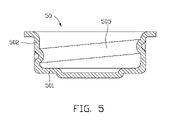
- FIG. 5 is a side cross-sectional view of a housing of a battery connecting structure according to a fourth exemplary embodiment of the present invention.
- FIG. 6 is a side cross-sectional view of a housing of a battery connecting structure according to a fifth exemplary embodiment of the present invention.
- FIG. 7 is a side cross-sectional view of a housing of a battery connecting structure according to a sixth exemplary embodiment of the present invention.
- the battery connecting structure 100 includes a contact spring 10 and a housing 20 .
- the contact spring 10 includes a plurality of loops 101 . Both ends of the contact spring 10 bend inward to avoid scratching a battery and the housing 20 .
- the housing 20 includes a base 201 , a sidewall 202 extending around a periphery of the base 201 .
- the base 201 is a circular plate forming a bottom protrusion 207 at a center of the base 201 .
- the housing 20 is made of phosphor bronze by punching and drawing processes.
- the bottom protrusion 207 is configured to match a bottom of a battery assembled cavity of the battery-powered device.
- the housing 20 further includes two retaining protrusions 205 formed at an inner surface on opposite sides the sidewall 202 . Also, a flange 206 extends from a top of the sidewall 202 .
- Each retaining protrusion 205 is substantially a hemispherical protrusion.
- One loop at an end of the contact spring 10 is tightly fixed between the base 201 and the retaining protrusions 205 such that the contact spring 10 is electrically fixed to the base 201 and the sidewall 202 of the housing 20 .
- the contact spring 10 is not easily detached from the housing 20 .
- each of the retaining protrusions 205 is a curved protrusion made by punching process.
- a maximum diameter of the contact spring 10 is equal to or larger than an inner diameter of the base 201 .
- This configuration allows the contact spring 10 to be partially received in the housing 20 .
- a distance between the retaining protrusion 205 and the base 201 equals to a diameter of each loop 101 of the contact spring 10 .
- the end of the contact spring 10 is secured into a space defined between the retaining protrusions 205 and the base 201 to avoid detaching from the housing 20 .
- the distance between the retaining protrusion 205 and the base 201 may be larger than the diameter of each loop so as to receive several loops 101 of the contact spring 10 .
- a housing 30 of a battery connecting structure in accordance with a second exemplary embodiment is shown.
- the housing 30 is similar in principle to the housing 20 of the first embodiment.
- two hooking protrusions 305 are formed at an inner surface of sidewall 302 , replacing the retaining protrusions 205 of the housing 20 .
- Each of the hooking protrusions 305 includes a blocking surface 3053 at a bottom of each hooking protrusion 305 and a steep inclined surface 3054 adjoining the blocking surface 3053 .
- An acute angle is defined between the blocking surface 3053 and the steep inclined surface 3054 .
- the blocking surface 3053 is perpendicular to the inner surface of the sidewall 302 .
- the blocking surface 3053 may be slanted to the inner surface of the sidewall 302 , thereby forming an acute angle relative to the inner surface of the sidewall 302 .
- a contact spring (not shown) is pressed into the housing 30 along the steep inclined surface 3054 of the hooking protrusion 305 .
- a part of the contact spring deforms and passes through the hooking protrusion 305 , and finally after passing through the hooking protrusion 305 , the contact spring returns to a free state and blocked by the blocking surface 3053 , such that the contact spring is electrically fixed to the housing 30 .
- a housing 40 of a battery connecting structure in accordance with a third exemplary embodiment is shown.
- the housing 40 is similar in principle to the housing 20 of the first embodiment.
- two resilient sheets 405 defined at an inner surface of sidewall 402 replace the two retaining protrusions 205 of the housing 20 .
- Each of the resilient sheets 405 extends from the inner surface of the sidewall 402 and inclines inwards.
- a contact spring (not shown) is pressed into the housing 40 , and a distal end of the resilient sheets 405 is compressed to move adjacent to the sidewall 402 , and finally the contact spring is pressed to contact the base 401 .
- the contact spring returns to a free state, the contact spring is blocked by the resilient sheets 405 , thereby the contact spring is electrically fixed to the housing 40 .
- a housing 50 of a battery connecting structure in accordance with a fourth exemplary embodiment is shown.
- the housing 50 is similar in principle to the housing 20 of the first embodiment.
- a threaded protrusion 505 defined at an inner surface of sidewall 502 replace the two retaining protrusions 205 of the housing 20 .
- the thread protrusion 505 extends around from a bottom portion of the sidewall 502 to a top portion of the sidewall 502 .
- a contact spring (not shown) is pressed into the housing 50 , and finally after passing through the threaded protrusion 505 , the contact spring returns to a free state and blocked by the threaded protrusion 505 , such that the contact spring is electrically fixed to the housing 50 .
- a housing 60 of a battery connecting structure in accordance with a fifth exemplary embodiment is shown.
- the housing 60 is similar in principle to the housing 20 of the first embodiment.
- the housing 60 includes a plurality of retaining protrusions 605 defined in an inner surface of sidewall 602 in random manner.
- a contact spring (not shown) is pressed into the housing 60 , and finally after passing through the retaining protrusions 605 , an end of the contact spring contacts the base 601 and returns to a free state, and blocked by the retaining protrusions 605 .
- the contact spring is electrically fixed to the housing 60 .
- a housing 70 of a battery connecting structure in accordance with a sixth exemplary embodiment is shown.
- the housing 70 is similar in principle to the housing 20 of the first embodiment.
- the housing 70 includes two retaining protrusions 705 defined in an inner surface of sidewall 702 .
- the housing 70 further includes a circular-depression 701 in a base 708 adjacent to the sidewall 702 .
- the circular-depression 701 is configured for receiving an end of a contact spring (not shown).
- the circular-depression 701 has a semi-circular cross-section taken along a direction perpendicular to the sidewall 702 to match a shape of the loops of the contact spring.
- the contact spring is pressed into the housing 70 until the distal end of the loop of the contact spring is received in the circular-depression 701 , and finally the contact spring returns to a free state, and is blocked by the retaining protrusions 705 .
- Contact areas between the contact spring and the housing 70 are increased due to the circular-depression 701 . This ensures the contact spring is electrically connected to the housing 70 .
- the housings 20 , 30 , 40 , 50 , 60 , 70 may be made of other metal materials such as magnesium alloy, aluminum alloy and so on.
- the housings 20 , 30 , 40 , 50 , 60 , 70 may further include a coating formed on an inner surface of the sidewalls 202 , 302 , 402 , 502 , 602 , 702 and the bases 201 , 401 , 601 , 708 for increasing electronic conduction performance.
- fixing portions including the retaining protrusion 205 , 605 , the hooking protrusion 305 , the resilient sheet 405 , and the thread protrusion 505 formed at the inner surface of the sidewall of the housing, can be replaced by any other elements that can block the contact spring.
Landscapes
- Battery Mounting, Suspending (AREA)
- Connection Of Batteries Or Terminals (AREA)
Abstract
Description
Claims (17)
Applications Claiming Priority (3)
| Application Number | Priority Date | Filing Date | Title |
|---|---|---|---|
| CN200810300530A CN101533982A (en) | 2008-03-12 | 2008-03-12 | Battery spring connection structure |
| CN200810300530 | 2008-03-12 | ||
| CN200810300530.2 | 2008-03-12 |
Publications (2)
| Publication Number | Publication Date |
|---|---|
| US20090233497A1 US20090233497A1 (en) | 2009-09-17 |
| US7654859B2 true US7654859B2 (en) | 2010-02-02 |
Family
ID=41063537
Family Applications (1)
| Application Number | Title | Priority Date | Filing Date |
|---|---|---|---|
| US12/125,884 Expired - Fee Related US7654859B2 (en) | 2008-03-12 | 2008-05-22 | Battery connecting structure |
Country Status (2)
| Country | Link |
|---|---|
| US (1) | US7654859B2 (en) |
| CN (1) | CN101533982A (en) |
Cited By (4)
| Publication number | Priority date | Publication date | Assignee | Title |
|---|---|---|---|---|
| US20110091757A1 (en) * | 2009-10-19 | 2011-04-21 | Hong Fu Jin Precision Industry (Shenzhen) Co., Ltd | Fixing mechanism |
| US20130188982A1 (en) * | 2012-01-23 | 2013-07-25 | Brother Kogyo Kabushiki Kaisha | Electrode for image forming apparatus and image forming apparatus |
| US9098057B2 (en) | 2012-11-30 | 2015-08-04 | Brother Kogyo Kabushiki Kaisha | Electrode and image forming apparatus |
| CN105422211A (en) * | 2015-12-10 | 2016-03-23 | 广东安飞汽车配件有限公司 | Oil filter bypass valve |
Families Citing this family (2)
| Publication number | Priority date | Publication date | Assignee | Title |
|---|---|---|---|---|
| EP2400578B1 (en) * | 2010-06-25 | 2013-04-03 | Samsung SDI Co., Ltd. | Secondary Battery |
| JP6297288B2 (en) * | 2013-09-18 | 2018-03-20 | 株式会社ヨコオ | Spring connector |
Citations (4)
| Publication number | Priority date | Publication date | Assignee | Title |
|---|---|---|---|---|
| US4343325A (en) | 1977-09-28 | 1982-08-10 | Draft Systems, Inc. | Valve assembly and coupler therefor |
| US5149598A (en) | 1991-07-11 | 1992-09-22 | Acr Electronics, Inc. | Battery arrangement |
| US5641315A (en) | 1995-11-16 | 1997-06-24 | Everett Charles Technologies, Inc. | Telescoping spring probe |
| US20050026033A1 (en) | 2003-07-31 | 2005-02-03 | Katsuya Kawano | Hermetically sealed battery |
-
2008
- 2008-03-12 CN CN200810300530A patent/CN101533982A/en active Pending
- 2008-05-22 US US12/125,884 patent/US7654859B2/en not_active Expired - Fee Related
Patent Citations (4)
| Publication number | Priority date | Publication date | Assignee | Title |
|---|---|---|---|---|
| US4343325A (en) | 1977-09-28 | 1982-08-10 | Draft Systems, Inc. | Valve assembly and coupler therefor |
| US5149598A (en) | 1991-07-11 | 1992-09-22 | Acr Electronics, Inc. | Battery arrangement |
| US5641315A (en) | 1995-11-16 | 1997-06-24 | Everett Charles Technologies, Inc. | Telescoping spring probe |
| US20050026033A1 (en) | 2003-07-31 | 2005-02-03 | Katsuya Kawano | Hermetically sealed battery |
Cited By (6)
| Publication number | Priority date | Publication date | Assignee | Title |
|---|---|---|---|---|
| US20110091757A1 (en) * | 2009-10-19 | 2011-04-21 | Hong Fu Jin Precision Industry (Shenzhen) Co., Ltd | Fixing mechanism |
| US8455125B2 (en) * | 2009-10-19 | 2013-06-04 | Hong Fu Jin Precision Industry (Shenzhen) Co., Ltd. | Fixing mechanism |
| US20130188982A1 (en) * | 2012-01-23 | 2013-07-25 | Brother Kogyo Kabushiki Kaisha | Electrode for image forming apparatus and image forming apparatus |
| US9046806B2 (en) * | 2012-01-23 | 2015-06-02 | Brother Kogyo Kabushiki Kaisha | Electrode for image forming apparatus and image forming apparatus |
| US9098057B2 (en) | 2012-11-30 | 2015-08-04 | Brother Kogyo Kabushiki Kaisha | Electrode and image forming apparatus |
| CN105422211A (en) * | 2015-12-10 | 2016-03-23 | 广东安飞汽车配件有限公司 | Oil filter bypass valve |
Also Published As
| Publication number | Publication date |
|---|---|
| CN101533982A (en) | 2009-09-16 |
| US20090233497A1 (en) | 2009-09-17 |
Similar Documents
| Publication | Publication Date | Title |
|---|---|---|
| US7654859B2 (en) | Battery connecting structure | |
| US7402082B2 (en) | Electrical connector with retaining shell | |
| US8184443B2 (en) | SIM card retention assembly | |
| CN107483677B (en) | Cover assembly, camera module and mobile terminal | |
| US7579107B2 (en) | Portable electronic device employing battery | |
| US20060263677A1 (en) | Battery seat having two positive terminals | |
| US20070117598A1 (en) | Battery cover latching assembly for portable electronic device | |
| US8253051B2 (en) | Power switch module and electronic device using the same | |
| US20060286443A1 (en) | Battery seat with a battery holder | |
| US20050001822A1 (en) | Resilient switch contact for a key switch device | |
| US20070048598A1 (en) | Battery seat with a battery holder | |
| US7300288B1 (en) | Electrical connector | |
| US6022248A (en) | Connecting terminal having enhanced biasing force | |
| US8406008B2 (en) | Portable electronic device with grounding mechanism | |
| US7396238B2 (en) | Battery contact system and wireless terminal having the same | |
| US7364456B2 (en) | Flexible contact device for use with a battery | |
| US7097485B1 (en) | Electrical connector having resilient conductive terminals | |
| US9142367B2 (en) | Electronic device and power button module thereof | |
| US7828605B1 (en) | Conducting mechanism for electronic device | |
| CN102087781B (en) | Electronic device | |
| US7835090B1 (en) | Clutching jig | |
| US20210166894A1 (en) | Electronic device | |
| US6457991B1 (en) | Electrical connector couple having mating indication device | |
| CN115086461B (en) | an electronic device | |
| US20110130043A1 (en) | Combination of socket and plug for battery connector |
Legal Events
| Date | Code | Title | Description |
|---|---|---|---|
| AS | Assignment |
Owner name: HON HAI PRECISION INDUSTRY CO., LTD.,TAIWAN Free format text: ASSIGNMENT OF ASSIGNORS INTEREST;ASSIGNOR:CHENG, DA-QING;REEL/FRAME:020988/0708 Effective date: 20080516 Owner name: HON HAI PRECISION INDUSTRY CO., LTD., TAIWAN Free format text: ASSIGNMENT OF ASSIGNORS INTEREST;ASSIGNOR:CHENG, DA-QING;REEL/FRAME:020988/0708 Effective date: 20080516 Owner name: HONG FU JIN PRECISION INDUSTRY (SHENZHEN) CO., LTD Free format text: ASSIGNMENT OF ASSIGNORS INTEREST;ASSIGNOR:CHENG, DA-QING;REEL/FRAME:020988/0708 Effective date: 20080516 |
|
| STCF | Information on status: patent grant |
Free format text: PATENTED CASE |
|
| FPAY | Fee payment |
Year of fee payment: 4 |
|
| FPAY | Fee payment |
Year of fee payment: 8 |
|
| FEPP | Fee payment procedure |
Free format text: MAINTENANCE FEE REMINDER MAILED (ORIGINAL EVENT CODE: REM.); ENTITY STATUS OF PATENT OWNER: LARGE ENTITY |
|
| LAPS | Lapse for failure to pay maintenance fees |
Free format text: PATENT EXPIRED FOR FAILURE TO PAY MAINTENANCE FEES (ORIGINAL EVENT CODE: EXP.); ENTITY STATUS OF PATENT OWNER: LARGE ENTITY |
|
| STCH | Information on status: patent discontinuation |
Free format text: PATENT EXPIRED DUE TO NONPAYMENT OF MAINTENANCE FEES UNDER 37 CFR 1.362 |
|
| FP | Lapsed due to failure to pay maintenance fee |
Effective date: 20220202 |