US7650100B2 - Development apparatus, image forming apparatus, and developer transfer method - Google Patents
Development apparatus, image forming apparatus, and developer transfer method Download PDFInfo
- Publication number
- US7650100B2 US7650100B2 US11/456,986 US45698606A US7650100B2 US 7650100 B2 US7650100 B2 US 7650100B2 US 45698606 A US45698606 A US 45698606A US 7650100 B2 US7650100 B2 US 7650100B2
- Authority
- US
- United States
- Prior art keywords
- developer
- conveying
- fluidity
- speed
- discharge port
- Prior art date
- Legal status (The legal status is an assumption and is not a legal conclusion. Google has not performed a legal analysis and makes no representation as to the accuracy of the status listed.)
- Expired - Fee Related, expires
Links
Images


Classifications
-
- G—PHYSICS
- G03—PHOTOGRAPHY; CINEMATOGRAPHY; ANALOGOUS TECHNIQUES USING WAVES OTHER THAN OPTICAL WAVES; ELECTROGRAPHY; HOLOGRAPHY
- G03G—ELECTROGRAPHY; ELECTROPHOTOGRAPHY; MAGNETOGRAPHY
- G03G15/00—Apparatus for electrographic processes using a charge pattern
- G03G15/06—Apparatus for electrographic processes using a charge pattern for developing
- G03G15/08—Apparatus for electrographic processes using a charge pattern for developing using a solid developer, e.g. powder developer
- G03G15/0822—Arrangements for preparing, mixing, supplying or dispensing developer
- G03G15/0848—Arrangements for testing or measuring developer properties or quality, e.g. charge, size, flowability
- G03G15/0849—Detection or control means for the developer concentration
- G03G15/0853—Detection or control means for the developer concentration the concentration being measured by magnetic means
-
- G—PHYSICS
- G03—PHOTOGRAPHY; CINEMATOGRAPHY; ANALOGOUS TECHNIQUES USING WAVES OTHER THAN OPTICAL WAVES; ELECTROGRAPHY; HOLOGRAPHY
- G03G—ELECTROGRAPHY; ELECTROPHOTOGRAPHY; MAGNETOGRAPHY
- G03G15/00—Apparatus for electrographic processes using a charge pattern
- G03G15/06—Apparatus for electrographic processes using a charge pattern for developing
- G03G15/08—Apparatus for electrographic processes using a charge pattern for developing using a solid developer, e.g. powder developer
- G03G15/0822—Arrangements for preparing, mixing, supplying or dispensing developer
- G03G15/0887—Arrangements for conveying and conditioning developer in the developing unit, e.g. agitating, removing impurities or humidity
- G03G15/0891—Arrangements for conveying and conditioning developer in the developing unit, e.g. agitating, removing impurities or humidity for conveying or circulating developer, e.g. augers
- G03G15/0893—Arrangements for conveying and conditioning developer in the developing unit, e.g. agitating, removing impurities or humidity for conveying or circulating developer, e.g. augers in a closed loop within the sump of the developing device
-
- G—PHYSICS
- G03—PHOTOGRAPHY; CINEMATOGRAPHY; ANALOGOUS TECHNIQUES USING WAVES OTHER THAN OPTICAL WAVES; ELECTROGRAPHY; HOLOGRAPHY
- G03G—ELECTROGRAPHY; ELECTROPHOTOGRAPHY; MAGNETOGRAPHY
- G03G2215/00—Apparatus for electrophotographic processes
- G03G2215/06—Developing structures, details
- G03G2215/0602—Developer
- G03G2215/0604—Developer solid type
- G03G2215/0607—Developer solid type two-component
-
- G—PHYSICS
- G03—PHOTOGRAPHY; CINEMATOGRAPHY; ANALOGOUS TECHNIQUES USING WAVES OTHER THAN OPTICAL WAVES; ELECTROGRAPHY; HOLOGRAPHY
- G03G—ELECTROGRAPHY; ELECTROPHOTOGRAPHY; MAGNETOGRAPHY
- G03G2215/00—Apparatus for electrophotographic processes
- G03G2215/08—Details of powder developing device not concerning the development directly
- G03G2215/0802—Arrangements for agitating or circulating developer material
- G03G2215/085—Stirring member in developer container
- G03G2215/0852—Stirring member in developer container reciprocating
Definitions
- the present invention relates to a development apparatus adopting a so-called overflow system, and particularly to a developer conveying technique.
- the developer which reaches the end of its life and is deteriorated is partially replaced by a new one, and the developer performance is kept, so that the number of times of collective replacement of the developer is reduced, and the maintenance property is improved.
- the invention has been made to solve the foregoing problems, and it is an object to provide a technique in which in a development apparatus to perform replacement of developer, the amount of the developer can be stably kept irrespective of a change in a physical property of the developer.
- a development apparatus is a development apparatus and includes a conveying chamber that circulates and conveys a developer supplied at a specified timing and causes the developer to overflow through a discharge port provided in the conveying chamber, a first conveying unit configured to convey the developer in a specified range near the discharge port in the conveying chamber, a second conveying unit configured to convey the developer in a conveying passage except the specified range in the conveying chamber, and a speed ratio changing unit capable of changing a speed ratio of a conveying speed of the developer by the first conveying unit to a conveying speed of the developer by the second conveying unit.
- an image forming apparatus includes a development apparatus that circulates and conveys a developer supplied at a specified timing in a specified conveying chamber and causes the developer to overflow through a discharge port provided in the conveying chamber, a fluidity judgment unit configured to judge a degree of fluidity of the developer in the conveying chamber, and a speed control unit configured to control a conveying speed of the developer in a specified range near the discharge port in the conveying chamber to become low relative to an average value of a conveying speed of the developer in a conveying passage except the specified range when the fluidity judged by the fluidity judgment unit is low.
- a developer conveying method is a developer conveying method in an image forming apparatus including a development apparatus that circulates and conveys a developer supplied at a specified timing in a specified conveying chamber and causes the developer to overflow through a discharge port provided in the conveying chamber, and includes judging a degree of fluidity of the developer in the conveying chamber, and controlling a conveying speed of the developer in a specified range near the discharge port in the conveying chamber to become low relative to an average value of a conveying speed of the developer in a conveying passage except the specified range when the judged fluidity is low.
- FIG. 1 is a whole structure view of an image forming apparatus of an embodiment.
- FIG. 2 is a functional block diagram for explaining the image forming apparatus of the embodiment.
- FIG. 3 is a view for explaining a structure of a development apparatus 1 Y.
- FIG. 4 is a view for explaining a structural example of a speed ratio changing unit 103 .
- FIG. 5 is a view for explaining a structural example of an area changing unit 103 ′.
- FIG. 6 is a view showing an example of a structure to move a developer in a development apparatus toward a horizontal direction by a developing roller.
- FIG. 7 is a view showing an example of a test machine for measuring the flow rate of developer in the development apparatus.
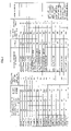
- FIG. 8 is a table showing evaluation results concerning a change in the amount of developer in a case where use conditions such as the life of the developer and an environment are changed.
- FIG. 9 is a flowchart for explaining the f low (developer conveying method) of a processing in the image forming apparatus of the embodiment.
- the flow rate of the developer in the vicinity of the discharge port is decelerated under a suitable condition, and an increase in the amount of the developer due to unnecessary accumulation of the developer in the other portion is eliminated.
- the deceleration (accumulation) is caused in the vicinity of the discharge port, so that the action is used for discharge, the discharge is efficiently performed, and the amount of the developer in the development apparatus can be stabilized.
- FIG. 1 is a whole structure view for explaining an image forming apparatus according to an embodiment.
- the image forming apparatus M of the embodiment includes an image reading unit R to read an image of a document, and an image forming unit P to form an image on a sheet. Besides, in the image forming apparatus M, based on image data read from the document by the image reading unit R, the image can be formed on the sheet by the image forming unit P.
- the image forming unit P includes process units Y, M, C and K, a paper feed cassette 901 , a register roller 902 , a secondary transfer roller 908 , a fixing unit 903 , a paper discharge roller 904 , an ADU (AUTO DUPLEX UNIT) 905 , a paper discharge tray 906 , an intermediate transfer belt 907 , a CPU 801 , and a MEMORY 802 .
- process units Y, M, C and K includes process units Y, M, C and K, a paper feed cassette 901 , a register roller 902 , a secondary transfer roller 908 , a fixing unit 903 , a paper discharge roller 904 , an ADU (AUTO DUPLEX UNIT) 905 , a paper discharge tray 906 , an intermediate transfer belt 907 , a CPU 801 , and a MEMORY 802 .
- ADU AUTO DUPLEX UNIT
- the respective process units Y, M, C and K integrally include photoconductive bodies 2 Y, 2 M, 2 C and 2 K, development apparatuses 1 Y, 1 M, 1 C and 1 K, chargers 3 Y, 3 M, 3 C and 3 K, and cleaning units 4 Y, 4 M, 4 C and 4 K.
- Each of the process units is attachably and detachably provided to a main body of the image forming apparatus.
- the development apparatuses 1 Y, 1 M, 1 C and 1 K are attachable to and detachable from the image forming apparatus M for maintenance and the like.
- the development apparatuses 1 Y, 1 M, 1 C and 1 K have structures in which while developer supplied at a specified timing is circulated and conveyed in an annular conveying chamber, the developer is overflown through a discharge port provided in a side wall (or a ceiling portion) of a housing of the conveying chamber.
- electrostatic latent images are formed on the photoconductive bodies 2 Y, 2 M, 2 C and 2 K in the respective process units.
- the electrostatic latent images formed on the photoconductive bodies 2 Y, 2 M, 2 C and 2 K in this way are visualized by the development apparatuses 1 Y, 1 M, 1 C and 1 K, and the visualized images are transferred to the sheet conveyed from the sheet cassette 901 through the register roller 902 to the secondary transfer roller 908 .
- the sheet on which the developer images have been transferred is heated and fixed to the sheet by the fixing unit 903 .
- the sheet on which the developer images have been heated and fixed is discharged onto the paper discharge tray 906 by the paper discharge roller 904 .
- the CPU 801 serves to perform various processings in the image forming apparatus M and also serves to realize various functions by executing programs stored in the MEMORY 802 .
- the MEMORY 802 includes, for example, a ROM, a RAM and the like, and serves to store various information and programs used in the image forming apparatus M.
- the structure of the color image forming apparatus using the normal electrophotographic system has been described as an example, no limitation is made to this, and the invention can be applied also to a monochrome image forming apparatus.
- the structure of the image forming apparatus of the so-called intermediate transfer system is used as an example, in addition to this, the invention can be applied also to an image forming apparatus of a system in which fixing is performed after plural color toners are superimposed on one photoconductive body and are transferred.
- FIG. 2 is a functional block diagram for explaining the image forming apparatus of the embodiment.
- the image forming apparatus M of the embodiment includes the development apparatuses 1 Y to 1 K, an environment detection unit 201 , a fluidity judgment unit 202 , a speed control unit 203 , the CPU 801 and the MEMORY 802 .
- the environment detection unit 201 detects the temperature and humidity in the development apparatuses 1 Y to 1 K.
- the fluidity judgment unit 202 serves to judge the degree of fluidity of the developer in a conveying chamber to circulate and convey the developer in the development apparatus.
- the fluidity judgment unit 202 judges that as the temperature and humidity detected by the environment detection unit 201 become high temperature and high humidity, the fluidity is low.
- a threshold as a high temperature and high humidity environment is set, and it is also possible to make a judgment that high temperature and high humidity are present in a case where the temperature and humidity exceed the threshold.
- the fluidity judgment unit 202 can make a judgment that as the number of times of image formation processing in the image forming apparatus from the time when a specified developer supply processing is performed for the conveying chamber (the time when the developer is replaced, the counter value is reset, or the like) becomes large (as the developer approaches the end of its life), the fluidity is low.
- the count of the number of times of image formation processing in the fluidity judgment unit 202 is performed based on the counter value to record the number of times of image formation processing in the image forming apparatus M.
- the fluidity judgment unit 202 judges that as the process speed at the time when the image formation processing is performed in the image forming apparatus M becomes low, the fluidity is low. Specifically, the fluidity judgment unit 202 judges that when the process speed (rotation speed of a mixer) is reduced, the fluidity becomes poor.
- the speed control unit 203 serves to perform such a control that when the fluidity judged by the fluidity judgment unit 202 is low, the conveying speed of the developer in a specified range near the discharge port in the conveying chamber becomes low relative to the average value of the conveying speed of the developer in the conveying passage except the specified range (or the average value of the conveying speed of the developer in the whole conveying chamber).
- the speed control unit 203 performs a control so that the conveying speed of the developer in the specified range near the discharge port 1 e in the conveying chamber H becomes the slowest speed among the developer conveying speeds in the conveying chamber H.
- FIG. 3 is a view for explaining the structure of the development apparatus 1 Y.
- the development apparatus 1 Y includes a developing roller 1 g , the conveying chamber H, a first conveying unit 101 , a second conveying unit 102 , a speed ratio changing unit 103 , and a toner density sensor 1 s.
- the conveying chamber H is for circulating and conveying the developer supplied at a specified timing, and causes the developer to overflow through a discharge port 1 e provided in the side wall of the conveying chamber H. As stated above, by adopting the overflow system, the replacement of the developer in the development apparatus is automatically performed.
- the first conveying unit 101 serves to convey the developer in the specified range near the discharge port in the conveying chamber H, and includes a spiral wing (auger) rotatable around a specified axis as a center axis.
- the second conveying unit 102 serves to convey the developer in the conveying passage except the specified range in the conveying chamber H, and includes a spiral wing (auger) rotatable around a specified axis as a center axis.
- the second conveying unit 102 can be rotation-driven independently of the first conveying unit 101 .
- the speed ratio changing unit 103 has a function to change the speed ratio of the conveying speed of the developer by the first conveying unit 101 to the conveying speed of the developer by the second conveying unit 102 based on the instruction (or power transmission) from the image forming apparatus M.
- the developing roller 1 g serves to transport the developer in the development apparatus 1 y to the photoconductive surface of the photoconductive body 2 Y.
- FIG. 4 is a view for explaining a structural example of the speed ratio changing unit 103 .
- the speed ratio changing unit 103 shown in the drawing is a mechanism to enable the first conveying unit 101 and the second conveying 102 to be independently rotation-driven by power transmission through a gear from the image forming apparatus M.
- the first conveying unit 101 and the second conveying unit 102 are disposed through seal bearings.
- the speed control unit 203 can change the ratio of the conveying speed of the developer by the first conveying unit 101 to the conveying speed of the developer by the second conveying unit 102 .
- FIG. 5 is a view for explaining a structural example of an area changing unit 103 ′.
- the area changing unit 103 ′ shown in the drawing is a structure which is adopted in a case where the rotation radius of the first conveying unit 101 is smaller than the rotation radius of the second conveying unit 102 (or in a case where the spiral wing of the auger does not exist only in the vicinity of the discharge port 1 e ), and the side wall in the conveying chamber H or the bottom near the discharge port 1 e can be made to protrude.
- the area changing unit 103 ′ it is not always necessary to divide the auger in the vicinity of the discharge port 1 e into the first and the second conveying units.
- the area changing unit 103 ′ has a structure in which a plate-like member 103 a ′ made of an elastic member is pressed and deformed from the outside of the housing of the development apparatus by a cam 103 b ′ rotation-driven by a motor or the like, so that it is protruded into the conveying chamber H. That is, the area changing unit 103 ′ has a function to change the sectional area (sectional area in a direction substantially perpendicular to the developer conveying direction) of the conveying passage in the specified range near the discharge port 1 e in the conveying chamber H based on the rotation angle of the cam 103 b ′.
- the rotation angle of the cam 103 b ′ is controlled based on, for example, the control signal from the CPU 801 .
- the speed control unit 203 can change the sectional area of the conveying passage in the specified range near the discharge port 1 e by the area changing unit 103 ′.
- the area changing unit 103 ′ in the case where the sectional area is narrowed, the flow passage of the developer is narrowed, and the conveying speed of the developer near the discharge port 1 e where the sectional area is narrowed becomes slow.
- the developer tends to swell in the vicinity of the discharge port 1 e in the conveying chamber H, and the stable discharge of the developer by the overflow becomes possible.
- the development apparatus 1 Y of the embodiment uses, as the developer, a two-component developer including a toner and a magnetic carrier, and uses, as the toner density sensor is, a well-known magnetic one (permeability sensor).
- the toner and carrier are supplied from a developer cartridge, are conveyed in the development apparatus, and are mixed with the developer. Since the carrier is supplied, the bulk of the developer in the development apparatus is increased, and accordingly, a bank is provided at the discharge port 1 e , and the discharge of the developer is performed using a fact that the developer overflows in a case where it exceeds a specified height.
- the structure has been described in which the developer in the development apparatus is moved in the vertical direction by the developing roller, no limitation is made to this, and for example, as shown in FIG. 6 , the structure may be such that the developer in the development apparatus is moved in the horizontal direction by the developing roller.
- the toner includes, as main ingredients, a binding resin and a coloring agent.
- a binding resin polystyrene, styrene acryl copolymer, polyester, epoxy resin, silicone resin, polyamide, paraffin wax or the like can be used.
- coloring agent a well-known pigment and dye are used, and carbon black, aniline blue, chrome yellow, ultra marine blue, copper phthalocyanine, pigment blue, pigment red, pigment yellow or the like is used.
- a charging control agent, a cleaning auxiliary agent, a peeling accelerating agent, a fluidity accelerating agent or the like can be included as the need arises.
- a magnetic particle of ferrite, iron oxide or the like is used, or these are used as core materials and what are obtained by covering them with resin can be used.
- the resin covering the carrier a well-known one such as fluorocarbon resin, acrylic resin, or silicone resin can be used, and one of or a combination of plural kinds of these can be used. Besides, what is obtained by mixing resin with magnetic powder can be used.
- the two-component developer in which the toner and carrier are mixed can be formed by a mixing apparatus such as a Henschel mixer.
- the developer for replenishment is prepared by mixing a small amount of carrier with toner.
- the toner density of the developer for replenishment was 90%.
- the toner and carrier can be separately replenished.
- FIG. 7 a development apparatus as shown in FIG. 7 was used as a test machine.
- magnetic toner density sensors were disposed at several places (1) to (6) in a conveying chamber H of developer and the measurement was performed.
- a small amount of toner was put in the place (3) in the development apparatus, and the outputs of the respective toner density sensors disposed were simultaneously monitored.
- the peak of an output value is detected.
- the developer conveying speed between the points can be measured.
- the conveying speed in the vicinity of the discharge port 1 e of the developer was obtained from the values measured between (1) and (2).
- the average conveying speed in the development apparatus was obtained from a time required for the developer to make a round from a point of a certain sensor (peak was again detected).
- the discharge position of the developer is not limited to the position as shown in the drawing.
- FIG. 8 is a table in which the evaluation results are listed. In the drawing,
- control parameter a deceleration rate of developer flow rate at discharge part, specific means of deceleration,
- output parameter a change in the amount of developer in actual machine evaluation, image defect, and others.
- angles of repose were measured as the developer fluidity before and after 300000 sheets were made for the developer life, and the developer with 30° at the beginning and 41° after the life was used.
- Example 1 mixer pitch 1 ⁇ 2,
- Example 3 mixer pitch 1 ⁇ 4.
- the mixer diameter and pitch of a normal developer conveying unit are made 1, and the conditions are indicated by multiples thereof.
- the apparatus shown in FIG. 7 was used, and the average flow rate of the developer in the development apparatus and the flow rate of the developer in the vicinity of the discharge port were measured.
- the average flow rate of the developer in the development apparatus is 50 mm/sec, and the deceleration ratio shown in FIG. 8 is determined by measuring the flow rate in the discharge part. The value of a is also shown.
- the discharge port was provided in a so-called corner portion where the flow direction of the developer in the conveying chamber H was changed.
- the deceleration ratio of the flow rate was measured and it was 0.4.
- FIG. 9 is a flowchart for explaining a processing flow (developer conveying method) in the image forming apparatus of the embodiment.
- the fluidity judgment unit 202 judges the degree of fluidity of developer in the conveying chamber H (S 101 ). Here, it is judged that as temperature and humidity in the development apparatus become high temperature and high humidity, the fluidity is low.
- the fluidity judgment unit 202 can also judge that as the number of times of image formation processing in the image forming apparatus M from the time when a specified developer supply processing is performed for the conveying chamber H becomes large, the fluidity is low.
- the image forming apparatus M can perform an image formation processing at plural process speeds different from each other, it is also possible to make a judgment that as the process speed at the time when the image formation processing is performed in the image forming apparatus M becomes low, the fluidity is low.
- the speed control unit 203 performs such a control that as the fluidity judged by the fluidity judgment unit 202 becomes low, the conveying speed of the developer in the specified range near the discharge port 1 e in the conveying chamber H becomes low relative to the average value of the conveying speed of the developer in the conveying passage except the specified range (S 102 ).
- the speed control unit 203 controls the conveying speed of the developer so that the relation between the deceleration ratio of the developer flow rate in the vicinity of the discharge port 1 e in the conveying chamber H to the average flow rate of the developer in the conveying chamber and the change rate of the developer fluidity becomes
- the angle of repose is used as the index indicating the fluidity of the developer.
- the conveyance of the developer in the specified range near the discharge port 1 e in the conveying chamber H and the conveyance of the developer in the conveying passage except the specified range are performed by the conveying means (the first conveying unit 101 and the second conveying means 102 ) which are different from each other and are controlled by the speed control unit 203 .
- the speed control unit 203 can also change the developer conveying speed in the specified range near the discharge port 1 e in the conveying chamber H by changing the sectional area of the conveying passage in the specified range near the discharge port 1 e in the conveying chamber H.
- the speed control unit 203 performs such a control that the conveying speed of the developer in the specified range near the discharge port 1 e in the conveying chamber H becomes the slowest speed among the developer conveying speeds in the conveying chamber H.
- the respective steps in the foregoing processing in the image forming apparatus are realized by causing the CPU 801 to execute a developer conveying program stored in the MEMORY 802 .
- the developer without large cost of, for example, new development of a developer that can suppress an environment variation and life variation, the developer can be stably discharged (the amount of developer in the development apparatus is stably kept at a specific amount) irrespective of a change in a developer physical property due to a change in a temperature and humidity environment.
- This embodiment can contribute to the stabilization of development identification as the development apparatus.
- the function to carry out the invention is previously recorded in the inside of the apparatus
- the same function may be downloaded from a network to the apparatus, or the same function stored in a storage medium may be installed into the apparatus.
- the recording medium as long as the recording medium can store a program, such as a CD-ROM, and the apparatus can read, any mode may be adopted.
- the function previously obtained by installation or download as stated above may be realized in cooperation with the OS (Operating System) in the inside of the apparatus.
- the technique in the development apparatus in which the developer is replaced, the technique can be provided in which the amount of developer can be stably kept irrespective of the change in the developer physical property.
Landscapes
- Physics & Mathematics (AREA)
- General Physics & Mathematics (AREA)
- Dry Development In Electrophotography (AREA)
Abstract
Description
V1/V2=0.1 to 0.7 (1)
V1/V2=0.1 to 0.7.
change degree of fluidity=angle of repose (after change)/angle of repose (initial state).
Claims (17)
V1/V2=0.1 to 0.7.
V1/V2=0.1 to 0.7.
Priority Applications (1)
| Application Number | Priority Date | Filing Date | Title |
|---|---|---|---|
| US11/456,986 US7650100B2 (en) | 2006-07-12 | 2006-07-12 | Development apparatus, image forming apparatus, and developer transfer method |
Applications Claiming Priority (1)
| Application Number | Priority Date | Filing Date | Title |
|---|---|---|---|
| US11/456,986 US7650100B2 (en) | 2006-07-12 | 2006-07-12 | Development apparatus, image forming apparatus, and developer transfer method |
Publications (2)
| Publication Number | Publication Date |
|---|---|
| US20080273888A1 US20080273888A1 (en) | 2008-11-06 |
| US7650100B2 true US7650100B2 (en) | 2010-01-19 |
Family
ID=39939611
Family Applications (1)
| Application Number | Title | Priority Date | Filing Date |
|---|---|---|---|
| US11/456,986 Expired - Fee Related US7650100B2 (en) | 2006-07-12 | 2006-07-12 | Development apparatus, image forming apparatus, and developer transfer method |
Country Status (1)
| Country | Link |
|---|---|
| US (1) | US7650100B2 (en) |
Cited By (3)
| Publication number | Priority date | Publication date | Assignee | Title |
|---|---|---|---|---|
| US20080240757A1 (en) * | 2007-03-29 | 2008-10-02 | Canon Kabushiki Kaisha | Imaging forming apparatus |
| US20080285985A1 (en) * | 2007-05-14 | 2008-11-20 | Samsung Electronics Co., Ltd. | Apparatus and method to supply developer |
| US10156823B2 (en) * | 2017-03-02 | 2018-12-18 | Kabushiki Kaisha Toshiba | Image forming apparatus and control method thereof |
Families Citing this family (10)
| Publication number | Priority date | Publication date | Assignee | Title |
|---|---|---|---|---|
| CN101738910A (en) * | 2008-11-17 | 2010-06-16 | 株式会社东芝 | Developing device, developing method, and image forming apparatus |
| US20120027432A1 (en) * | 2010-07-30 | 2012-02-02 | Brown Kenneth J | Electrophotographic developer flow rate measurement |
| JP6337609B2 (en) * | 2014-05-19 | 2018-06-06 | 株式会社リコー | Flow velocity measuring apparatus and image forming apparatus |
| JP6145654B2 (en) * | 2014-11-19 | 2017-06-14 | コニカミノルタ株式会社 | Developing device and image forming apparatus |
| JP6308175B2 (en) * | 2015-06-19 | 2018-04-11 | 京セラドキュメントソリューションズ株式会社 | Developing device and image forming apparatus including the same |
| JP6717157B2 (en) * | 2016-10-13 | 2020-07-01 | コニカミノルタ株式会社 | Developing device and image forming device |
| JP2018136422A (en) * | 2017-02-21 | 2018-08-30 | コニカミノルタ株式会社 | Image forming apparatus |
| JP6828499B2 (en) * | 2017-02-21 | 2021-02-10 | コニカミノルタ株式会社 | Image forming device and developing device |
| JP7009918B2 (en) * | 2017-10-30 | 2022-01-26 | コニカミノルタ株式会社 | Developing equipment and image forming equipment |
| JP7071160B2 (en) * | 2018-02-28 | 2022-05-18 | キヤノン株式会社 | Image forming device |
Citations (4)
| Publication number | Priority date | Publication date | Assignee | Title |
|---|---|---|---|---|
| JPH09185177A (en) | 1995-12-28 | 1997-07-15 | Fuji Xerox Co Ltd | Two-component developer for replenishment and developing method using the same |
| JP2000081787A (en) | 1998-09-04 | 2000-03-21 | Fuji Xerox Co Ltd | Developing device |
| JP2001215797A (en) * | 2000-01-28 | 2001-08-10 | Fuji Xerox Co Ltd | Developing device |
| US7003233B2 (en) * | 2002-08-30 | 2006-02-21 | Canon Kabushiki Kaisha | Image forming apparatus with a toner replenishing control feature based on stored toner density and fluidity information, related method, and developing agent replenishing container for same |
-
2006
- 2006-07-12 US US11/456,986 patent/US7650100B2/en not_active Expired - Fee Related
Patent Citations (4)
| Publication number | Priority date | Publication date | Assignee | Title |
|---|---|---|---|---|
| JPH09185177A (en) | 1995-12-28 | 1997-07-15 | Fuji Xerox Co Ltd | Two-component developer for replenishment and developing method using the same |
| JP2000081787A (en) | 1998-09-04 | 2000-03-21 | Fuji Xerox Co Ltd | Developing device |
| JP2001215797A (en) * | 2000-01-28 | 2001-08-10 | Fuji Xerox Co Ltd | Developing device |
| US7003233B2 (en) * | 2002-08-30 | 2006-02-21 | Canon Kabushiki Kaisha | Image forming apparatus with a toner replenishing control feature based on stored toner density and fluidity information, related method, and developing agent replenishing container for same |
Cited By (5)
| Publication number | Priority date | Publication date | Assignee | Title |
|---|---|---|---|---|
| US20080240757A1 (en) * | 2007-03-29 | 2008-10-02 | Canon Kabushiki Kaisha | Imaging forming apparatus |
| US7729641B2 (en) * | 2007-03-29 | 2010-06-01 | Canon Kabushiki Kaisha | Imaging forming apparatus |
| US20080285985A1 (en) * | 2007-05-14 | 2008-11-20 | Samsung Electronics Co., Ltd. | Apparatus and method to supply developer |
| US8045867B2 (en) * | 2007-05-14 | 2011-10-25 | Samsung Electronics Co., Ltd. | Apparatus and method to supply developer |
| US10156823B2 (en) * | 2017-03-02 | 2018-12-18 | Kabushiki Kaisha Toshiba | Image forming apparatus and control method thereof |
Also Published As
| Publication number | Publication date |
|---|---|
| US20080273888A1 (en) | 2008-11-06 |
Similar Documents
| Publication | Publication Date | Title |
|---|---|---|
| US7650100B2 (en) | Development apparatus, image forming apparatus, and developer transfer method | |
| US8023839B2 (en) | Developing apparatus and image forming machine | |
| US8090276B2 (en) | Developing device and image forming apparatus | |
| US20090290886A1 (en) | Developing apparatus and image forming machine | |
| US7840146B2 (en) | Developing device and image forming apparatus | |
| US7860435B2 (en) | Developing device | |
| US8190065B2 (en) | Developing device and image forming apparatus | |
| US9811026B2 (en) | Developing device | |
| JP5194478B2 (en) | Image forming apparatus | |
| US20090103943A1 (en) | Developer, developing device, image forming apparatus, process cartridge, and image forming method | |
| US8190045B2 (en) | Developing device and image forming apparatus | |
| US8331810B2 (en) | Developing apparatus and image forming machine | |
| KR20120135369A (en) | Developer and electrophotographic image forming apparatus employing the same | |
| JP5277900B2 (en) | Developing device and image forming apparatus | |
| JP4617094B2 (en) | Image forming apparatus | |
| US7167667B2 (en) | Developing apparatus and electrostatic recording apparatus using the same | |
| US20110150535A1 (en) | Developing apparatus and image forming apparatus provided with the same | |
| US9448521B2 (en) | Image forming apparatus and control method | |
| US11852989B2 (en) | Developing device | |
| US8233827B2 (en) | Developing apparatus and image forming apparatus provided with the same | |
| JP6011107B2 (en) | Image forming apparatus and toner density control method thereof | |
| JP2004157186A (en) | How to replenish developer | |
| US20250208533A1 (en) | Image forming apparatus | |
| JP4645660B2 (en) | Developing device and image forming apparatus | |
| JP4914516B2 (en) | Image forming apparatus |
Legal Events
| Date | Code | Title | Description |
|---|---|---|---|
| AS | Assignment |
Owner name: TOSHIBA TEC KABUSHIKI KAISHA, JAPAN Free format text: ASSIGNMENT OF ASSIGNORS INTEREST;ASSIGNORS:MURATA, HIROSHI;YOSHIDA, MINORU;HATAKEYAMA, TAKASHI;REEL/FRAME:017923/0351 Effective date: 20060703 Owner name: KABUSHIKI KAISHA TOSHIBA, JAPAN Free format text: ASSIGNMENT OF ASSIGNORS INTEREST;ASSIGNORS:MURATA, HIROSHI;YOSHIDA, MINORU;HATAKEYAMA, TAKASHI;REEL/FRAME:017923/0351 Effective date: 20060703 |
|
| STCF | Information on status: patent grant |
Free format text: PATENTED CASE |
|
| FPAY | Fee payment |
Year of fee payment: 4 |
|
| FPAY | Fee payment |
Year of fee payment: 8 |
|
| FEPP | Fee payment procedure |
Free format text: MAINTENANCE FEE REMINDER MAILED (ORIGINAL EVENT CODE: REM.); ENTITY STATUS OF PATENT OWNER: LARGE ENTITY |
|
| LAPS | Lapse for failure to pay maintenance fees |
Free format text: PATENT EXPIRED FOR FAILURE TO PAY MAINTENANCE FEES (ORIGINAL EVENT CODE: EXP.); ENTITY STATUS OF PATENT OWNER: LARGE ENTITY |
|
| STCH | Information on status: patent discontinuation |
Free format text: PATENT EXPIRED DUE TO NONPAYMENT OF MAINTENANCE FEES UNDER 37 CFR 1.362 |
|
| FP | Lapsed due to failure to pay maintenance fee |
Effective date: 20220119 |