US7650074B2 - Optical transmission apparatus - Google Patents
Optical transmission apparatus Download PDFInfo
- Publication number
- US7650074B2 US7650074B2 US11/319,362 US31936205A US7650074B2 US 7650074 B2 US7650074 B2 US 7650074B2 US 31936205 A US31936205 A US 31936205A US 7650074 B2 US7650074 B2 US 7650074B2
- Authority
- US
- United States
- Prior art keywords
- light
- ase
- optical
- wdm
- waveband
- Prior art date
- Legal status (The legal status is an assumption and is not a legal conclusion. Google has not performed a legal analysis and makes no representation as to the accuracy of the status listed.)
- Active, expires
Links
Images


Classifications
-
- H—ELECTRICITY
- H04—ELECTRIC COMMUNICATION TECHNIQUE
- H04J—MULTIPLEX COMMUNICATION
- H04J14/00—Optical multiplex systems
- H04J14/02—Wavelength-division multiplex systems
- H04J14/0221—Power control, e.g. to keep the total optical power constant
-
- H—ELECTRICITY
- H04—ELECTRIC COMMUNICATION TECHNIQUE
- H04B—TRANSMISSION
- H04B10/00—Transmission systems employing electromagnetic waves other than radio-waves, e.g. infrared, visible or ultraviolet light, or employing corpuscular radiation, e.g. quantum communication
- H04B10/29—Repeaters
- H04B10/291—Repeaters in which processing or amplification is carried out without conversion of the main signal from optical form
- H04B10/293—Signal power control
- H04B10/294—Signal power control in a multiwavelength system, e.g. gain equalisation
- H04B10/296—Transient power control, e.g. due to channel add/drop or rapid fluctuations in the input power
-
- H—ELECTRICITY
- H04—ELECTRIC COMMUNICATION TECHNIQUE
- H04J—MULTIPLEX COMMUNICATION
- H04J14/00—Optical multiplex systems
- H04J14/02—Wavelength-division multiplex systems
- H04J14/0201—Add-and-drop multiplexing
- H04J14/0202—Arrangements therefor
- H04J14/0213—Groups of channels or wave bands arrangements
-
- H—ELECTRICITY
- H04—ELECTRIC COMMUNICATION TECHNIQUE
- H04B—TRANSMISSION
- H04B2210/00—Indexing scheme relating to optical transmission systems
- H04B2210/25—Distortion or dispersion compensation
- H04B2210/258—Distortion or dispersion compensation treating each wavelength or wavelength band separately
-
- H—ELECTRICITY
- H04—ELECTRIC COMMUNICATION TECHNIQUE
- H04J—MULTIPLEX COMMUNICATION
- H04J14/00—Optical multiplex systems
- H04J14/02—Wavelength-division multiplex systems
- H04J14/0201—Add-and-drop multiplexing
- H04J14/0202—Arrangements therefor
- H04J14/0204—Broadcast and select arrangements, e.g. with an optical splitter at the input before adding or dropping
-
- H—ELECTRICITY
- H04—ELECTRIC COMMUNICATION TECHNIQUE
- H04J—MULTIPLEX COMMUNICATION
- H04J14/00—Optical multiplex systems
- H04J14/02—Wavelength-division multiplex systems
- H04J14/0201—Add-and-drop multiplexing
- H04J14/0202—Arrangements therefor
- H04J14/0205—Select and combine arrangements, e.g. with an optical combiner at the output after adding or dropping
Definitions
- the present invention relates to an optical transmission apparatus that transmits optical signals by wavelength-multiplexing the optical signals in an optical network.
- WDM wavelength division multiplexing
- OADM optical add and drop multiplexer
- FIG. 8 is a schematic of an OADM in a multi-stage connection in a backbone optical network.
- a backbone optical network 9 plural N units ( 10 a to 10 n ) of OADMs 10 are disposed on an optical transmission path (an optical fiber 140 ) to transmit optical signals.
- the backbone optical network 9 is, for example, a ring network.
- Each OADM 10 ( 10 a to 10 n ) includes an optical amplifier 11 that amplifies a wavelength division multiplexed (WDM) light output from the optical fiber 140 , a add/drop multiplexing unit 20 that adds and drops an optical signal for each channel of the WDM light, and an optical amplifier 12 that amplifies the added or dropped WDM light, and inputs the amplified WDM light to the optical fiber 140 .
- WDM wavelength division multiplexed
- the OADM 10 a at a position A adds optical signals of five waves
- the OADM 10 b at a position B adds an optical signal of one wave
- the OADM 10 n at a position N drops optical signals of five waves.
- Each OADM 10 on the backbone optical network 9 frequently adds and drops optical signals.
- the optical fiber 140 at a position X between the position A and the position B is broken, and only one optical signal of one wave is transmitted to the optical fibers 140 at the position B and subsequent positions. Even when the number of operating wavelengths changes frequently, the backbone optical network 9 (the OADM 10 ( 10 a to 10 n )) needs to maintain communication quality for each optical signal.
- the optical amplifiers 11 and 12 in the OADM 10 control the gain of the input WDM light at a constant level. Specifically, regardless of the number of operating wavelengths of the WDM light, the output gain of each signal is set constant.
- FIG. 9 is a schematic of the add/drop multiplexing unit. Assume that the WDM light is transmitted to a direction of an arrow A shown in FIG. 9 .
- An add/drop multiplexing unit 20 includes a drop port 21 , a demultiplexing filter 22 , a variable optical attenuator (VOA) 23 , a multiplexer 24 , and an add port 25 .
- FIG. 10 depicts an output of the WDM light.
- the horizontal axis represents a wavelength ( ⁇ ), and the vertical axis represents power (Po) of each optical signal of the WDM light.
- the WDM light is transmitted while optical signals of wavelengths ⁇ a to ⁇ n and an amplified spontaneous emission light (ASE) are accumulated as noise in the whole area.
- ASE amplified spontaneous emission light
- the optical amplifier 11 When the WDM light as shown in FIG. 10 is input to the OADM 10 , the optical amplifier 11 amplifies the WDM light, and outputs the amplified WDM light to the add/drop multiplexing unit 20 .
- the add/drop multiplexing unit 20 passes the whole optical signals without adding or dropping an optical signal, the demultiplexing filter 22 demultiplexes the signals into signals of wavelengths, and inputs the optical signals to the variable optical attenuator 23 . In this case, light other than the optical signals of the wavelengths ⁇ a to ⁇ n is not demultiplexed. Therefore, the ASE other than those near the optical signals of the wavelengths ⁇ a to ⁇ n is removed.
- variable optical attenuator 23 attenuates the optical signals of the input optical signals of the wavelengths ⁇ a to ⁇ n, thereby correcting the signal waveform and adjusting the output level, and outputs the corrected result to the multiplexer 24 .
- the multiplexer 24 multiplexes again the optical signals demultiplexed into those of different wavelengths, and outputs the multiplexed optical signals to the optical fiber 140 .
- FIG. 11 depicts the WDM light output from the add/drop multiplexing unit.
- the horizontal axis represents a wavelength ( ⁇ ), and the vertical axis represents power (Po) of each optical signal of the WDM light.
- the WDM light output from the add/drop multiplexing unit 20 includes the optical signals of the wavelengths ⁇ a to ⁇ n, and the ASEs ( ⁇ a_ase to ⁇ n_ase). In this way, when viewed from a certain OADM 10 , the output of each optical signal is set constant to maintain the communication quality (see, for example, Japanese Patent Application Laid-Open No. 2001-111495).
- FIG. 12 is a schematic for illustrating a change in the number of operating wavelengths of the WDM light input to the optical amplifier.
- the horizontal axis represents a wavelength ( ⁇ ), and the vertical axis represents power (Po) of each optical signal of the WDM light.
- FIG. 12 depicts the change of states from a time 1201 to a time 1202 after a lapse of a time t. It is explained below that optical signals of six operating wavelengths ⁇ a to ⁇ f of the WDM signals input to the optical amplifier 11 or the optical amplifier 12 at the time 1201 change to an optical signal of only one wave ⁇ f at the time 1202 .
- FIG. 13 depicts a change in the wavelength when optical signals having six waves change to an optical signal having one wave in the conventional OADM.
- the horizontal axis represents a wavelength ( ⁇ ), and the vertical axis represents power (Po) of each optical signal of the WDM light.
- FIG. 13 depicts the change of states from a time 1301 to a time 1302 after a lapse of a time t.
- the WDM light including the optical signals having six operating wavelengths ⁇ a to ⁇ f at the time 1201 as shown in FIG. 12 is input to the OADM 10 .
- the ASE other than the optical signals is removed as described above. Therefore, the WDM light including the optical signals having the six wavelengths ⁇ a to ⁇ f, and the ASEs ( ⁇ a_ase to ⁇ f_ase) is output at the time 1301 .
- the WDM light including the optical signal of only one wave as shown at the time 1202 in FIG. 12 is input to the OADM 10 .
- the WDM light passes through the demultiplexing filter 22 , the WDM light at the time 1302 as shown in FIG. 13 is output.
- the WDM light includes the optical signal having the wavelength ⁇ f, and the ASE ( ⁇ a_ase to ⁇ f_ase).
- This WDM light with these wavelengths is input to the optical amplifier 12 .
- the optical amplifier 12 detects the power of the whole wavelengths of the optical signals to control the gain.
- the optical amplifier 12 controls the gain so that the gain becomes constant based on the power of the ASE ( ⁇ a_ase to ⁇ f_ase) in the state of the optical signals of the six waves immediately before the number of the operating wavelengths transitionally changes, immediately after the number of the wavelengths of the optical signals becomes one.
- FIG. 14 is a schematic for illustrating the output of the optical amplifier in the change of the operating wavelengths shown in FIG. 12 .
- the horizontal axis represents a wavelength ( ⁇ ), and the vertical axis represents power (Po) of each optical signal of the WDM light.
- FIG. 14 depicts the change of states from a time 1401 to a time 1402 after a lapse of a time t. Assume that in the state shown in FIG. 13 , the optical signal of one wave ⁇ f has predetermined power among the six waves ⁇ a to ⁇ f having the power as shown at the time 1401 in FIG. 14 .
- the optical amplifier 11 ( 12 ) decreases the intrinsic power of the one wave ⁇ f by a portion indicated by an arrow D to the power shown at the time 1402 .
- the optical amplifier 11 ( 12 ) controls the gain in the form of averaging the whole wavelengths ⁇ a to ⁇ f at the time 1041 . Therefore, the optical amplifier 11 ( 12 ) controls the gain such that the power of the one wave ⁇ f at the time 1402 is affected by the power level of the five waves ⁇ a to ⁇ e at the time 1401 when the power levels are substantially arranged.
- the gain variation can be disregarded as a minor gain variation.
- the OADMs 10 are connected in multiple stages as the OADMs 10 a to 10 n in the actual backbone optical network 9 as shown in FIG. 8 , as optical signals are dropped from and added to the OADMs 10 toward the latter stages on the transmission path, this gain variation is gradually accumulated.
- the accumulated gain variation becomes too large, the gain of optical signals becomes smaller than that of the reception ranges, and the optical signals cannot be recognized. As a result, a reception error occurs, and communication quality is degraded.
- the OADM disclosed in Japanese Patent Application Laid-Open No. 2001-111495 has a function of preventing reduction in the gain level.
- the function requires an additional light source to be provided in the OADM. This increases both cost and size.
- An optical transmission apparatus includes a branching unit configured to branch a light input to the optical transmission apparatus into a plurality of lights; an optical attenuator configured to adjust an output level of a light within a band that includes a signal light from among branched lights; a bypass unit configured to bypass a light outside the band from among branched lights; a multiplexing unit configured to multiplex adjusted light and the light from the bypass unit; and an optical amplifier configured to amplify input light.
- the optical amplifier is provided at least one of a stage prior to the branching unit and a stage subsequent to the multiplexing unit.
- FIG. 1 is a schematic of an OADM according to embodiments of the present invention.
- FIG. 2 depicts an amplification band of a WDM signal amplified by an optical amplifier
- FIG. 3 depicts optical signals and ASEs that are multiplexed by a 2 ⁇ 1 optical coupler
- FIG. 4 depicts a change in wavelengths when an optical signal of six waves is changed to an optical signal of one wave in the OADM according to the present invention
- FIG. 5 depicts gain variation following a change in the number of operating wavelengths in a conventional OADM
- FIG. 6 depicts gain variation following a change in the number of operating wavelengths in an OADM according to embodiments of the present invention
- FIG. 7 is a graph of an output variation when OADMs are connected in multiple stages
- FIG. 8 is a schematic of an OADM in a multi-stage connection in a backbone optical network
- FIG. 9 is a schematic of an add/drop multiplexing unit
- FIG. 10 depicts an output of a WDM light
- FIG. 11 depicts the WDM light output from the add/drop multiplexing unit
- FIG. 12 is a schematic for illustrating a change in the number of operating wavelengths of the WDM light input to the optical amplifier
- FIG. 13 depicts a change in the wavelength when optical signals having six waves change to an optical signal having one wave in the conventional OADM.
- FIG. 14 is a schematic for illustrating the output of the optical amplifier in the change of the operating wavelengths shown in FIG. 12 .
- FIG. 1 is a schematic of an OADM according to embodiments of the present invention.
- Plural units of OADMs 100 shown in FIG. 1 are disposed in the backbone optical network 9 , and are used to transmit WDM signals.
- Each OADM 100 includes optical amplifiers 110 and 130 and an optical add/drop multiplexing unit 120 , and is connected to the optical fiber 140 .
- the optical add/drop multiplexing unit 120 includes a drop port 121 , a optical coupler (a 1 ⁇ 2 optical coupler) 122 as a branching unit that branches an input light, a demultiplexing filter 123 , a variable optical attenuator (VOA) 124 as an optical attenuator that adjusts an optical output level of a band including optical signals, a multiplexer 125 , a signal-band blocking filter 126 , a variable optical attenuator (VOA) 127 , a optical coupler (a 2 ⁇ 1 optical coupler) 128 as a multiplexing unit, and an add port 129 .
- a drop port 121 includes a drop port 121 , a optical coupler (a 1 ⁇ 2 optical coupler) 122 as a branching unit that branches an input light, a demultiplexing filter 123 , a variable optical attenuator (VOA) 124 as an optical attenuator that adjusts an optical output level of a band including optical signals,
- the 1 ⁇ 2 optical coupler 122 demultiplexes an input optical signal into two, outputs one of the demultiplexed optical signals to the demultiplexing filter 123 , and outputs the other optical signal to the signal-band blocking filter 126 .
- a route R 1 is an optical route for a light in a band including the optical signal (the signal light).
- the other route R 2 functions as a bypass unit that bypasses light outside the band including the optical signal.
- a WDM light including multiplexed optical signals of different wavelengths ⁇ a to ⁇ n in a specific band is transmitted through the optical fiber 140 .
- the WDM light is output from the optical fiber 140 to the OADM 100 .
- the WDM light that is input to the OADM 100 is first input to the optical amplifier 110 .
- the optical amplifier 110 amplifies the input WDM light, and outputs the amplified WDM light to the optical add/drop multiplexing unit 120 .
- the optical amplifier 110 is set to amplify the band of the input WDM light, that is, the light having a wider band than the waveband ( ⁇ a to ⁇ n) of the optical signals. Therefore, the optical amplifier 110 also amplifies the ASE included in the wavelength shorter than and the wavelength longer than the waveband of the optical signals respectively.
- FIG. 2 depicts an amplification band of the WDM signal amplified by the optical amplifier.
- the horizontal axis represents a wavelength ( ⁇ )
- the vertical axis represents power (Po) of each optical signal of the WDM light.
- a general optical amplifier amplifies only an optical signal amplification band B shown in the diagram 200 .
- the optical amplifier 110 according to the present invention shown in FIG. 1 amplifies a wide band indicated by a solid line of the input ASE in addition to the optical signal amplification band B indicated by a dotted line.
- This optical amplifier 110 can be obtained by changing a transmission factor (a wavelength characteristic) of a filter incorporated in the optical amplifier.
- the WDM light output to the optical add/drop multiplexing unit 120 is input to the 1 ⁇ 2 optical coupler 122 via the drop port 121 .
- the optical signal to be dropped from among the optical signals multiplexed into the WDM light is dropped from the drop port 121 .
- the 1 ⁇ 2 optical coupler 122 demultiplexes the input WDM light into two, outputs one demultiplexed light to the demultiplexing filter 123 , and outputs the other demultiplexed light to the signal-band blocking filter 126 .
- the 1 ⁇ 2 optical coupler 122 demultiplexes the multiplexed optical signals regardless of the wavelengths included in the WDM light.
- the demultiplexing filter 123 demultiplexes the input WDM light into optical signals of the wavelengths ⁇ a to ⁇ n, and outputs the optical signals to the corresponding variable optical attenuator 124 .
- the variable optical attenuator 124 has plural variable optical attenuators 124 a to 124 n corresponding to the demultiplexed wavelengths. Each variable optical attenuator adjusts the level of the input optical signal, and outputs the adjusted optical signal to the multiplexer 125 .
- the multiplexer 125 multiplexes the optical signals input from the variable optical attenuator 124 for each optical signal, into the WDM light again, and outputs the WDM light to the 2 ⁇ 1 optical coupler 128 .
- the signal-band blocking filter 126 blocks only the light of the wavelengths ⁇ a to ⁇ n in the optical signal amplification band B out of the WDM light that is output to the signal-band blocking filter 126 from the 1 ⁇ 2 optical coupler 122 .
- the signal-band blocking filter 126 passes the ASE (ASE 1 and ASE 2 ) having wavelengths shorter than ⁇ a and longer than ⁇ n that are other than the wavelengths ⁇ a to ⁇ n in the optical signal amplification band B, and outputs the ASE 1 and the ASE 2 to the variable optical attenuator 127 .
- the variable optical attenuator 127 adjusts the level of the input ASE, and outputs the adjusted ASE to the 2 ⁇ 1 optical coupler 128 .
- the OADM 100 can be configured without providing the variable optical attenuator 127 .
- the transmission factor of the ASE to be passed is set high and the ASE is output at a high level, the ASE oscillates in the transmission path and this affects the optical signals. Therefore, an upper limit is set to the transmission factor of the ASE in the variable optical attenuator 127 .
- FIG. 3 depicts the optical signals and the ASE that are multiplexed by the 2 ⁇ 1 optical coupler 128 .
- the horizontal axis represents a wavelength
- the vertical axis represents power of each optical signal of the WDM light.
- the 2 ⁇ 1 optical coupler 128 multiplexes the WDM light having the wavelengths ⁇ a to ⁇ n output from the multiplexer 125 with the ASE (ASE 1 and ASE 2 ) demultiplexed and output from the variable optical attenuator 127 .
- the multiplexed WDM light includes the optical signals having the wavelengths ⁇ a to ⁇ n in the optical signal amplification band B, and the ASE (ASE 1 and ASE 2 ) in the band the outside the optical signal amplification band B.
- the optical signals having the wavelengths ⁇ a to ⁇ n include the ASE ( ⁇ a_ase to ⁇ n_ase).
- the WDM light obtained by multiplexing with the 2 ⁇ 1 optical coupler 128 is output to the optical amplifier 130 via the add port 129 .
- this optical signal is added from the add port 129 .
- the optical amplifier 130 For the optical amplifier 130 to amplify the optical signals having the wavelengths ⁇ a to ⁇ n included in the WDM signal, and the ASE (the ASE 1 and the ASE 2 ), similarly to the optical amplifier 110 , a larger amplification band is set to the optical amplifier 130 than the amplification band set to the general optical amplifier.
- the amplified WDM light is output to the optical fiber 140 . While the optical amplifier 110 is disposed at a stage before the optical coupler 122 and the optical amplifier 130 is disposed at a stage after the optical coupler 128 , only one of these optical amplifiers can be provided.
- FIG. 4 depicts a change in the wavelengths when an optical signal of six waves is changed to an optical signal of one wave in the OADM according to the present invention.
- the horizontal axis represents a wavelength
- the vertical axis represents power of each optical signal.
- the OADM 100 has an optical signal having six operating wavelengths ⁇ a to ⁇ f.
- the optical signals change to an optical signal having only one operating wavelength ⁇ f.
- the ASE 1 and the ASE 2 remain in the WDM light as background respectively.
- the number of operating wavelengths changes due to a drop by the OADM 100 or breakage of the optical fiber 140 .
- the optical signal having six operating wavelengths ⁇ a to ⁇ f at the time 401 changes to the optical signal having only one operating wavelength ⁇ f by decreasing five operating wavelengths ⁇ a to ⁇ e at the time 402 .
- the optical amplifiers 110 and 130 carry out the output control by matching the power of the optical signal having one operating wavelength ⁇ f, based on the ASE (the ASE 1 and the ASE 2 , ⁇ a_ase to ⁇ n_ase) as the background.
- the power of the ASE does not change even after the number of the operating wavelengths changes. Therefore, variation in the gain can be suppressed.
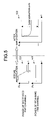
- FIG. 5 depicts gain variation following a change in the number of operating wavelengths in the conventional OADM.
- FIG. 6 depicts gain variation following a change in the number of operating wavelengths in the OADM according to the present invention.
- the horizontal axis represents lapse of time (t)
- the vertical axis represents power (Po) of the WDM light.
- power 501 of the WDM light in the optical amplifier 12 shows a change in the power of the decreased five waves (equivalent to channels: for example, the wavelengths ⁇ a to ⁇ e in FIG. 12 ).
- the power of the five waves (channels) decreases to the power of the ASE ( ⁇ a_ase to ⁇ e_ase) after the time t 1 (at the reduction time).
- power 502 is the power of the remaining one wave (channel: the wavelength ⁇ f in FIG. 12 ), and constant power is maintained. Therefore, as shown in a characteristic line 503 , a gain variation ⁇ Po after the amplification carried out by the optical amplifier 12 is large.
- power 801 shows a change in the power of the decreased five waves (channels: for example, the wavelengths ⁇ a to ⁇ e in FIG. 4 ) and the ASE accumulated power.
- a characteristic line 802 after the optical amplifier 120 amplifies the optical signals (or the optical amplifier 110 , when the reduction of the number of wavelengths is due to dropping or due to breakage of the optical fiber 140 ), the gain variation ⁇ Po can be decreased from that shown in the characteristic line 503 in FIG. 5 .
- FIG. 7 is a graph of an output variation when OADMs are connected at multiple stages.
- the horizontal axis represents the number of OADMs connected at multiple stages in the backbone optical network
- the vertical axis represents a variation in the output (decibel) when the number of operating wavelengths of the WDM light in the OADMs changes from five waves to one wave.
- Values of plotted black squares show a characteristic line 701 according to the conventional OADMs 10 (see FIG. 8 )
- values of plotted white squares show a characteristic line 702 according to the OADMs 100 (see FIG. 1 ) of the present invention.
- the OADM 100 according to the present invention can also pass the ASE (the ASE 1 and the ASE 2 , see FIG. 4 ) other than the band of the optical signals. Therefore, when the number of the operating wavelengths of the WDM light changes, the OADM 100 can decrease the variation in the power of the optical signals. When the number of connected OADMs 100 is small, the variation in the output is small. Therefore, the OADM according to the present invention and the conventional OADM 10 show little difference in the output variation. However, when the number of the OADMs 100 increases, the output variation increases. As a result, when 15 OADMs 100 are connected, the gain variation can be improved by 2.6 decibels, as compared with the conventional OADMs 10 .
- the OADM 100 does not require an additional light source for reducing the gain variation, and uses the ASE as the light source using optical couplers (the 1 ⁇ 2 optical coupler 122 , and the 2 ⁇ 1 optical coupler 128 shown in FIG. 1 ) and a filter (the signal-band blocking filter 126 ). Therefore, cost can be suppressed. Furthermore, the size of the OADM 100 remains unchanged from the size of the OADM having the conventional function.
- the OADM 100 according to the present invention can substantially decrease the transitional gain variation when the number of operating wavelengths changes, compared to the conventional OADM. Consequently, even when the OADMs 100 are connected in multiple stages in the backbone optical network connecting between cities, the communication quality can be maintained.
Landscapes
- Engineering & Computer Science (AREA)
- Computer Networks & Wireless Communication (AREA)
- Signal Processing (AREA)
- Physics & Mathematics (AREA)
- Electromagnetism (AREA)
- Optical Communication System (AREA)
- Lasers (AREA)
Abstract
Description
Claims (14)
Applications Claiming Priority (2)
| Application Number | Priority Date | Filing Date | Title |
|---|---|---|---|
| JP2005100137A JP4557771B2 (en) | 2005-03-30 | 2005-03-30 | Optical transmission equipment |
| JP2005-100137 | 2005-03-30 |
Publications (2)
| Publication Number | Publication Date |
|---|---|
| US20060222366A1 US20060222366A1 (en) | 2006-10-05 |
| US7650074B2 true US7650074B2 (en) | 2010-01-19 |
Family
ID=37070619
Family Applications (1)
| Application Number | Title | Priority Date | Filing Date |
|---|---|---|---|
| US11/319,362 Active 2026-12-14 US7650074B2 (en) | 2005-03-30 | 2005-12-29 | Optical transmission apparatus |
Country Status (2)
| Country | Link |
|---|---|
| US (1) | US7650074B2 (en) |
| JP (1) | JP4557771B2 (en) |
Cited By (1)
| Publication number | Priority date | Publication date | Assignee | Title |
|---|---|---|---|---|
| JP5700117B2 (en) * | 2011-03-25 | 2015-04-15 | 日本電気株式会社 | Optical transmission equipment |
Families Citing this family (10)
| Publication number | Priority date | Publication date | Assignee | Title |
|---|---|---|---|---|
| JP4806640B2 (en) * | 2007-01-12 | 2011-11-02 | 日本放送協会 | Optical transmission equipment |
| WO2010050921A1 (en) * | 2008-10-31 | 2010-05-06 | Hewlett-Packard Development Company, L.P. | Prioritized optical arbitration systems and methods |
| JP5321041B2 (en) | 2008-12-24 | 2013-10-23 | 富士通株式会社 | Optical add / drop multiplexer and WDM transmission method |
| WO2011114042A1 (en) * | 2010-03-18 | 2011-09-22 | France Telecom | Method and device for inserting/extracting optical subband into multiband optical ofdm signal |
| US9794019B2 (en) | 2011-04-28 | 2017-10-17 | Hewlett Packard Enterprise Development Lp | Prioritized optical arbitration systems and methods |
| JP6050067B2 (en) * | 2012-09-18 | 2016-12-21 | Necエンジニアリング株式会社 | Optical transmission device and control method of optical transmission device |
| WO2017002322A1 (en) * | 2015-06-30 | 2017-01-05 | 日本電気株式会社 | Communication device, communication method, and communication system |
| JP6578962B2 (en) * | 2016-01-25 | 2019-09-25 | 富士通株式会社 | Optical transmission device, optical transmission system, and optical signal output control method |
| WO2019003833A1 (en) * | 2017-06-27 | 2019-01-03 | 住友電気工業株式会社 | Optical receiver module, optical reception method, station-side device, pon system, and optical filter |
| US12199741B2 (en) * | 2022-09-28 | 2025-01-14 | Fujitsu Limited | Optical transmission system, optical transmission device, and optical transmission method |
Citations (5)
| Publication number | Priority date | Publication date | Assignee | Title |
|---|---|---|---|---|
| JP2000232433A (en) | 1999-02-08 | 2000-08-22 | Fujitsu Ltd | WDM optical communication system and optical amplifier |
| JP2001111495A (en) | 1999-10-04 | 2001-04-20 | Fujitsu Ltd | Optical add / drop device and control method therefor |
| US6233092B1 (en) | 1998-10-16 | 2001-05-15 | Corning Incorporated | Management and utilization of ASE in optical amplifier |
| US20060018658A1 (en) * | 2004-07-20 | 2006-01-26 | Shota Mori | Wavelength division multiplexing optical transmission system |
| US7356259B1 (en) * | 2003-06-18 | 2008-04-08 | Ciena Corporation | Optical bypass upgrade configuration |
Family Cites Families (5)
| Publication number | Priority date | Publication date | Assignee | Title |
|---|---|---|---|---|
| ITMI20010695A1 (en) * | 2001-03-30 | 2002-09-30 | Marconi Comm Spa | METHOD AND DEVICE FOR SURVIVAL OF TRAFFIC IN DWDM SYSTEMS WITH ADD / DROP IN THE EVENT OF INTERRUPTION OF THE OPTICAL FIBER CONNECTION |
| JP2002353939A (en) * | 2001-05-25 | 2002-12-06 | Kddi Submarine Cable Systems Inc | Optical transmitter |
| ITMI20040431A1 (en) * | 2004-03-05 | 2004-06-05 | Marconi Comm Spa | CONNECTION-DISCONNECTION OPTICAL AMPLIFICATION DEVICE |
| US7526201B2 (en) * | 2004-06-25 | 2009-04-28 | Tyco Telecommunications (Us) Inc. | Optical fiber transmission system with noise loading |
| JP4569222B2 (en) * | 2004-08-24 | 2010-10-27 | 日本電気株式会社 | Optical add / drop apparatus and optical add / drop method |
-
2005
- 2005-03-30 JP JP2005100137A patent/JP4557771B2/en not_active Expired - Fee Related
- 2005-12-29 US US11/319,362 patent/US7650074B2/en active Active
Patent Citations (8)
| Publication number | Priority date | Publication date | Assignee | Title |
|---|---|---|---|---|
| US6233092B1 (en) | 1998-10-16 | 2001-05-15 | Corning Incorporated | Management and utilization of ASE in optical amplifier |
| JP2002528901A (en) | 1998-10-16 | 2002-09-03 | コーニング・インコーポレーテッド | ASE processing and utilization of optical amplifiers |
| JP2000232433A (en) | 1999-02-08 | 2000-08-22 | Fujitsu Ltd | WDM optical communication system and optical amplifier |
| US6639716B1 (en) | 1999-02-08 | 2003-10-28 | Fujitsu Limited | Wavelength division multiplexing optical communication system and optical amplifying device |
| JP2001111495A (en) | 1999-10-04 | 2001-04-20 | Fujitsu Ltd | Optical add / drop device and control method therefor |
| US6922280B1 (en) | 1999-10-04 | 2005-07-26 | Fujitsu Limited | Optical amplifying apparatus, optical add/drop multiplexer, and optical amplifying method |
| US7356259B1 (en) * | 2003-06-18 | 2008-04-08 | Ciena Corporation | Optical bypass upgrade configuration |
| US20060018658A1 (en) * | 2004-07-20 | 2006-01-26 | Shota Mori | Wavelength division multiplexing optical transmission system |
Cited By (1)
| Publication number | Priority date | Publication date | Assignee | Title |
|---|---|---|---|---|
| JP5700117B2 (en) * | 2011-03-25 | 2015-04-15 | 日本電気株式会社 | Optical transmission equipment |
Also Published As
| Publication number | Publication date |
|---|---|
| JP4557771B2 (en) | 2010-10-06 |
| JP2006279896A (en) | 2006-10-12 |
| US20060222366A1 (en) | 2006-10-05 |
Similar Documents
| Publication | Publication Date | Title |
|---|---|---|
| US8204379B2 (en) | Noise reduction in optical communications networks | |
| JP3821920B2 (en) | Optical communication system | |
| US6278536B1 (en) | Optical transmission device for bi-directional optical communication | |
| US7650072B2 (en) | Method of upgrading optical node, and an optical node apparatus | |
| US7277608B2 (en) | Optical transmitter | |
| US8682167B2 (en) | Optical transmission device | |
| US6577652B1 (en) | Optical add-drop multiplexer of WDM optical signals | |
| EP1630992A2 (en) | System and method for modularly scalable architecture for optical networks | |
| US7650074B2 (en) | Optical transmission apparatus | |
| JP5887698B2 (en) | Optical coupling / branching device and optical coupling / branching method | |
| US7519296B2 (en) | Optical demultiplexing method and optical multiplexing method, and optical transmission apparatus using same | |
| JP3938270B2 (en) | Optical repeater amplifier | |
| US7072585B2 (en) | Per-channel optical amplification using saturation mode | |
| JP4826451B2 (en) | Optical transmission device with optical amplifier | |
| US20050157976A1 (en) | Optical receiver and optical transmission apparatus | |
| US6646792B2 (en) | Light amplifier and light transmission system using the same | |
| JP4522894B2 (en) | Wavelength division multiplexing communication system. | |
| EP1863202B1 (en) | An optical transmission system with gain adjustment | |
| EP2071755B1 (en) | Optical Add-Drop Multiplexer | |
| JP2002198911A (en) | Means of optical level automatic controle and optical signal receiving system equipped with its | |
| US20150180583A1 (en) | Wavelength division multiplexing optical transmission device | |
| JPH1198079A (en) | Wavelength multiple light supervisory system and wavelength multiple light supervising device |
Legal Events
| Date | Code | Title | Description |
|---|---|---|---|
| AS | Assignment |
Owner name: FUJITSU LIMITED, JAPAN Free format text: ASSIGNMENT OF ASSIGNORS INTEREST;ASSIGNOR:SAGAYA, YASHUSHI;REEL/FRAME:017421/0930 Effective date: 20051103 |
|
| AS | Assignment |
Owner name: FUJITSU LIMITED, JAPAN Free format text: TO CORRECT ASSIGNOR NAME ON REEL/FRAME 017421/0930;ASSIGNOR:SUGAYA, YASUSHI;REEL/FRAME:018985/0266 Effective date: 20051103 |
|
| FEPP | Fee payment procedure |
Free format text: PAYOR NUMBER ASSIGNED (ORIGINAL EVENT CODE: ASPN); ENTITY STATUS OF PATENT OWNER: LARGE ENTITY Free format text: PAYER NUMBER DE-ASSIGNED (ORIGINAL EVENT CODE: RMPN); ENTITY STATUS OF PATENT OWNER: LARGE ENTITY |
|
| STCF | Information on status: patent grant |
Free format text: PATENTED CASE |
|
| CC | Certificate of correction | ||
| FPAY | Fee payment |
Year of fee payment: 4 |
|
| FPAY | Fee payment |
Year of fee payment: 8 |
|
| MAFP | Maintenance fee payment |
Free format text: PAYMENT OF MAINTENANCE FEE, 12TH YEAR, LARGE ENTITY (ORIGINAL EVENT CODE: M1553); ENTITY STATUS OF PATENT OWNER: LARGE ENTITY Year of fee payment: 12 |