US7648033B2 - Method of producing particle-dispersed liquid - Google Patents
Method of producing particle-dispersed liquid Download PDFInfo
- Publication number
- US7648033B2 US7648033B2 US11/236,824 US23682405A US7648033B2 US 7648033 B2 US7648033 B2 US 7648033B2 US 23682405 A US23682405 A US 23682405A US 7648033 B2 US7648033 B2 US 7648033B2
- Authority
- US
- United States
- Prior art keywords
- particles
- particle
- dispersed liquid
- flow channel
- core flow
- Prior art date
- Legal status (The legal status is an assumption and is not a legal conclusion. Google has not performed a legal analysis and makes no representation as to the accuracy of the status listed.)
- Expired - Fee Related, expires
Links
- 239000007788 liquid Substances 0.000 title claims abstract description 148
- 238000000034 method Methods 0.000 title claims abstract description 75
- 239000002245 particle Substances 0.000 claims abstract description 215
- 230000005484 gravity Effects 0.000 claims description 25
- 239000012530 fluid Substances 0.000 description 42
- 238000011084 recovery Methods 0.000 description 23
- 238000002156 mixing Methods 0.000 description 17
- 238000000926 separation method Methods 0.000 description 17
- XLYOFNOQVPJJNP-UHFFFAOYSA-N water Substances O XLYOFNOQVPJJNP-UHFFFAOYSA-N 0.000 description 15
- 229920005989 resin Polymers 0.000 description 12
- 239000011347 resin Substances 0.000 description 12
- 239000000463 material Substances 0.000 description 8
- 229910052751 metal Inorganic materials 0.000 description 8
- 239000002184 metal Substances 0.000 description 8
- 238000010586 diagram Methods 0.000 description 5
- -1 polyethylene Polymers 0.000 description 5
- 229920001577 copolymer Polymers 0.000 description 4
- 150000002736 metal compounds Chemical class 0.000 description 4
- 239000003960 organic solvent Substances 0.000 description 4
- 239000000126 substance Substances 0.000 description 4
- ZWEHNKRNPOVVGH-UHFFFAOYSA-N 2-Butanone Chemical compound CCC(C)=O ZWEHNKRNPOVVGH-UHFFFAOYSA-N 0.000 description 3
- YMWUJEATGCHHMB-UHFFFAOYSA-N Dichloromethane Chemical compound ClCCl YMWUJEATGCHHMB-UHFFFAOYSA-N 0.000 description 3
- LFQSCWFLJHTTHZ-UHFFFAOYSA-N Ethanol Chemical compound CCO LFQSCWFLJHTTHZ-UHFFFAOYSA-N 0.000 description 3
- OKKJLVBELUTLKV-UHFFFAOYSA-N Methanol Chemical compound OC OKKJLVBELUTLKV-UHFFFAOYSA-N 0.000 description 3
- CTQNGGLPUBDAKN-UHFFFAOYSA-N O-Xylene Chemical compound CC1=CC=CC=C1C CTQNGGLPUBDAKN-UHFFFAOYSA-N 0.000 description 3
- 239000000356 contaminant Substances 0.000 description 3
- 230000008021 deposition Effects 0.000 description 3
- 238000000605 extraction Methods 0.000 description 3
- 238000005259 measurement Methods 0.000 description 3
- 229910044991 metal oxide Inorganic materials 0.000 description 3
- 150000004706 metal oxides Chemical class 0.000 description 3
- 239000000203 mixture Substances 0.000 description 3
- 239000007787 solid Substances 0.000 description 3
- 239000008096 xylene Substances 0.000 description 3
- CSCPPACGZOOCGX-UHFFFAOYSA-N Acetone Chemical compound CC(C)=O CSCPPACGZOOCGX-UHFFFAOYSA-N 0.000 description 2
- XKRFYHLGVUSROY-UHFFFAOYSA-N Argon Chemical compound [Ar] XKRFYHLGVUSROY-UHFFFAOYSA-N 0.000 description 2
- HEDRZPFGACZZDS-UHFFFAOYSA-N Chloroform Chemical compound ClC(Cl)Cl HEDRZPFGACZZDS-UHFFFAOYSA-N 0.000 description 2
- XEEYBQQBJWHFJM-UHFFFAOYSA-N Iron Chemical compound [Fe] XEEYBQQBJWHFJM-UHFFFAOYSA-N 0.000 description 2
- CPLXHLVBOLITMK-UHFFFAOYSA-N Magnesium oxide Chemical compound [Mg]=O CPLXHLVBOLITMK-UHFFFAOYSA-N 0.000 description 2
- LRHPLDYGYMQRHN-UHFFFAOYSA-N N-Butanol Chemical compound CCCCO LRHPLDYGYMQRHN-UHFFFAOYSA-N 0.000 description 2
- PXHVJJICTQNCMI-UHFFFAOYSA-N Nickel Chemical compound [Ni] PXHVJJICTQNCMI-UHFFFAOYSA-N 0.000 description 2
- 239000004698 Polyethylene Substances 0.000 description 2
- WYURNTSHIVDZCO-UHFFFAOYSA-N Tetrahydrofuran Chemical compound C1CCOC1 WYURNTSHIVDZCO-UHFFFAOYSA-N 0.000 description 2
- GWEVSGVZZGPLCZ-UHFFFAOYSA-N Titan oxide Chemical compound O=[Ti]=O GWEVSGVZZGPLCZ-UHFFFAOYSA-N 0.000 description 2
- 229920002433 Vinyl chloride-vinyl acetate copolymer Polymers 0.000 description 2
- XLOMVQKBTHCTTD-UHFFFAOYSA-N Zinc monoxide Chemical compound [Zn]=O XLOMVQKBTHCTTD-UHFFFAOYSA-N 0.000 description 2
- 238000005299 abrasion Methods 0.000 description 2
- 239000012615 aggregate Substances 0.000 description 2
- 150000001298 alcohols Chemical class 0.000 description 2
- 238000004364 calculation method Methods 0.000 description 2
- 238000003889 chemical engineering Methods 0.000 description 2
- MVPPADPHJFYWMZ-UHFFFAOYSA-N chlorobenzene Chemical compound ClC1=CC=CC=C1 MVPPADPHJFYWMZ-UHFFFAOYSA-N 0.000 description 2
- 238000011109 contamination Methods 0.000 description 2
- 239000013078 crystal Substances 0.000 description 2
- 239000006185 dispersion Substances 0.000 description 2
- 238000009826 distribution Methods 0.000 description 2
- 239000002923 metal particle Substances 0.000 description 2
- 150000002739 metals Chemical class 0.000 description 2
- 239000000113 methacrylic resin Substances 0.000 description 2
- 150000004767 nitrides Chemical class 0.000 description 2
- 239000003921 oil Substances 0.000 description 2
- 239000012188 paraffin wax Substances 0.000 description 2
- 238000005192 partition Methods 0.000 description 2
- 229920000573 polyethylene Polymers 0.000 description 2
- 239000011148 porous material Substances 0.000 description 2
- BDERNNFJNOPAEC-UHFFFAOYSA-N propan-1-ol Chemical compound CCCO BDERNNFJNOPAEC-UHFFFAOYSA-N 0.000 description 2
- XOLBLPGZBRYERU-UHFFFAOYSA-N tin dioxide Chemical compound O=[Sn]=O XOLBLPGZBRYERU-UHFFFAOYSA-N 0.000 description 2
- 238000011144 upstream manufacturing Methods 0.000 description 2
- DHKHKXVYLBGOIT-UHFFFAOYSA-N 1,1-Diethoxyethane Chemical compound CCOC(C)OCC DHKHKXVYLBGOIT-UHFFFAOYSA-N 0.000 description 1
- RYHBNJHYFVUHQT-UHFFFAOYSA-N 1,4-Dioxane Chemical compound C1COCCO1 RYHBNJHYFVUHQT-UHFFFAOYSA-N 0.000 description 1
- XNWFRZJHXBZDAG-UHFFFAOYSA-N 2-METHOXYETHANOL Chemical compound COCCO XNWFRZJHXBZDAG-UHFFFAOYSA-N 0.000 description 1
- ZNQVEEAIQZEUHB-UHFFFAOYSA-N 2-ethoxyethanol Chemical compound CCOCCO ZNQVEEAIQZEUHB-UHFFFAOYSA-N 0.000 description 1
- KXGFMDJXCMQABM-UHFFFAOYSA-N 2-methoxy-6-methylphenol Chemical compound [CH]OC1=CC=CC([CH])=C1O KXGFMDJXCMQABM-UHFFFAOYSA-N 0.000 description 1
- 239000004925 Acrylic resin Substances 0.000 description 1
- 229920000178 Acrylic resin Polymers 0.000 description 1
- 239000004215 Carbon black (E152) Substances 0.000 description 1
- VYZAMTAEIAYCRO-UHFFFAOYSA-N Chromium Chemical compound [Cr] VYZAMTAEIAYCRO-UHFFFAOYSA-N 0.000 description 1
- UNPLRYRWJLTVAE-UHFFFAOYSA-N Cloperastine hydrochloride Chemical compound Cl.C1=CC(Cl)=CC=C1C(C=1C=CC=CC=1)OCCN1CCCCC1 UNPLRYRWJLTVAE-UHFFFAOYSA-N 0.000 description 1
- RYGMFSIKBFXOCR-UHFFFAOYSA-N Copper Chemical compound [Cu] RYGMFSIKBFXOCR-UHFFFAOYSA-N 0.000 description 1
- 239000004743 Polypropylene Substances 0.000 description 1
- 239000004372 Polyvinyl alcohol Substances 0.000 description 1
- 229920001328 Polyvinylidene chloride Polymers 0.000 description 1
- XBDQKXXYIPTUBI-UHFFFAOYSA-M Propionate Chemical compound CCC([O-])=O XBDQKXXYIPTUBI-UHFFFAOYSA-M 0.000 description 1
- 229910052581 Si3N4 Inorganic materials 0.000 description 1
- RTAQQCXQSZGOHL-UHFFFAOYSA-N Titanium Chemical compound [Ti] RTAQQCXQSZGOHL-UHFFFAOYSA-N 0.000 description 1
- YXFVVABEGXRONW-UHFFFAOYSA-N Toluene Chemical compound CC1=CC=CC=C1 YXFVVABEGXRONW-UHFFFAOYSA-N 0.000 description 1
- HCHKCACWOHOZIP-UHFFFAOYSA-N Zinc Chemical compound [Zn] HCHKCACWOHOZIP-UHFFFAOYSA-N 0.000 description 1
- 239000011354 acetal resin Substances 0.000 description 1
- KXKVLQRXCPHEJC-UHFFFAOYSA-N acetic acid trimethyl ester Natural products COC(C)=O KXKVLQRXCPHEJC-UHFFFAOYSA-N 0.000 description 1
- 239000002253 acid Substances 0.000 description 1
- 230000004913 activation Effects 0.000 description 1
- 239000003513 alkali Substances 0.000 description 1
- 229920000180 alkyd Polymers 0.000 description 1
- 239000000956 alloy Substances 0.000 description 1
- 229910045601 alloy Inorganic materials 0.000 description 1
- 229910052782 aluminium Inorganic materials 0.000 description 1
- XAGFODPZIPBFFR-UHFFFAOYSA-N aluminium Chemical compound [Al] XAGFODPZIPBFFR-UHFFFAOYSA-N 0.000 description 1
- 238000004458 analytical method Methods 0.000 description 1
- GHPGOEFPKIHBNM-UHFFFAOYSA-N antimony(3+);oxygen(2-) Chemical compound [O-2].[O-2].[O-2].[Sb+3].[Sb+3] GHPGOEFPKIHBNM-UHFFFAOYSA-N 0.000 description 1
- 229910052786 argon Inorganic materials 0.000 description 1
- 230000015572 biosynthetic process Effects 0.000 description 1
- 239000006229 carbon black Substances 0.000 description 1
- 239000005018 casein Substances 0.000 description 1
- BECPQYXYKAMYBN-UHFFFAOYSA-N casein, tech. Chemical compound NCCCCC(C(O)=O)N=C(O)C(CC(O)=O)N=C(O)C(CCC(O)=N)N=C(O)C(CC(C)C)N=C(O)C(CCC(O)=O)N=C(O)C(CC(O)=O)N=C(O)C(CCC(O)=O)N=C(O)C(C(C)O)N=C(O)C(CCC(O)=N)N=C(O)C(CCC(O)=N)N=C(O)C(CCC(O)=N)N=C(O)C(CCC(O)=O)N=C(O)C(CCC(O)=O)N=C(O)C(COP(O)(O)=O)N=C(O)C(CCC(O)=N)N=C(O)C(N)CC1=CC=CC=C1 BECPQYXYKAMYBN-UHFFFAOYSA-N 0.000 description 1
- 235000021240 caseins Nutrition 0.000 description 1
- 239000001913 cellulose Substances 0.000 description 1
- 229920002678 cellulose Polymers 0.000 description 1
- 239000000919 ceramic Substances 0.000 description 1
- 229910010293 ceramic material Inorganic materials 0.000 description 1
- 238000006243 chemical reaction Methods 0.000 description 1
- 239000007795 chemical reaction product Substances 0.000 description 1
- HGAZMNJKRQFZKS-UHFFFAOYSA-N chloroethene;ethenyl acetate Chemical class ClC=C.CC(=O)OC=C HGAZMNJKRQFZKS-UHFFFAOYSA-N 0.000 description 1
- 229910052804 chromium Inorganic materials 0.000 description 1
- 239000011651 chromium Substances 0.000 description 1
- 238000004140 cleaning Methods 0.000 description 1
- 238000005345 coagulation Methods 0.000 description 1
- 230000015271 coagulation Effects 0.000 description 1
- 239000000084 colloidal system Substances 0.000 description 1
- 150000001875 compounds Chemical class 0.000 description 1
- 238000010276 construction Methods 0.000 description 1
- 229910052802 copper Inorganic materials 0.000 description 1
- 239000010949 copper Substances 0.000 description 1
- JHIVVAPYMSGYDF-UHFFFAOYSA-N cyclohexanone Chemical compound O=C1CCCCC1 JHIVVAPYMSGYDF-UHFFFAOYSA-N 0.000 description 1
- 238000009792 diffusion process Methods 0.000 description 1
- 239000012153 distilled water Substances 0.000 description 1
- 230000000694 effects Effects 0.000 description 1
- 229920001971 elastomer Polymers 0.000 description 1
- 239000003822 epoxy resin Substances 0.000 description 1
- 239000010419 fine particle Substances 0.000 description 1
- 239000011521 glass Substances 0.000 description 1
- 229930195733 hydrocarbon Natural products 0.000 description 1
- 150000002430 hydrocarbons Chemical class 0.000 description 1
- PJXISJQVUVHSOJ-UHFFFAOYSA-N indium(III) oxide Inorganic materials [O-2].[O-2].[O-2].[In+3].[In+3] PJXISJQVUVHSOJ-UHFFFAOYSA-N 0.000 description 1
- 230000002401 inhibitory effect Effects 0.000 description 1
- 239000010954 inorganic particle Substances 0.000 description 1
- 238000005342 ion exchange Methods 0.000 description 1
- 238000010884 ion-beam technique Methods 0.000 description 1
- 150000002500 ions Chemical class 0.000 description 1
- 229910052742 iron Inorganic materials 0.000 description 1
- 238000004519 manufacturing process Methods 0.000 description 1
- 238000010299 mechanically pulverizing process Methods 0.000 description 1
- 229910052976 metal sulfide Inorganic materials 0.000 description 1
- 229910052759 nickel Inorganic materials 0.000 description 1
- 230000003647 oxidation Effects 0.000 description 1
- 238000007254 oxidation reaction Methods 0.000 description 1
- 229920001568 phenolic resin Polymers 0.000 description 1
- 239000013034 phenoxy resin Substances 0.000 description 1
- 229920006287 phenoxy resin Polymers 0.000 description 1
- WVDDGKGOMKODPV-ZQBYOMGUSA-N phenyl(114C)methanol Chemical compound O[14CH2]C1=CC=CC=C1 WVDDGKGOMKODPV-ZQBYOMGUSA-N 0.000 description 1
- 239000000049 pigment Substances 0.000 description 1
- 229920003023 plastic Polymers 0.000 description 1
- 239000004033 plastic Substances 0.000 description 1
- 229920002037 poly(vinyl butyral) polymer Polymers 0.000 description 1
- 229920002401 polyacrylamide Polymers 0.000 description 1
- 229920006122 polyamide resin Polymers 0.000 description 1
- 229920005668 polycarbonate resin Polymers 0.000 description 1
- 239000004431 polycarbonate resin Substances 0.000 description 1
- 229920000647 polyepoxide Polymers 0.000 description 1
- 229920000728 polyester Polymers 0.000 description 1
- 229920001225 polyester resin Polymers 0.000 description 1
- 239000004645 polyester resin Substances 0.000 description 1
- 229920000098 polyolefin Polymers 0.000 description 1
- 229920006324 polyoxymethylene Polymers 0.000 description 1
- 229920001155 polypropylene Polymers 0.000 description 1
- 229920005990 polystyrene resin Polymers 0.000 description 1
- 229920005749 polyurethane resin Polymers 0.000 description 1
- 239000011118 polyvinyl acetate Substances 0.000 description 1
- 229920002689 polyvinyl acetate Polymers 0.000 description 1
- 229920002451 polyvinyl alcohol Polymers 0.000 description 1
- 229920000915 polyvinyl chloride Polymers 0.000 description 1
- 239000004800 polyvinyl chloride Substances 0.000 description 1
- 239000005033 polyvinylidene chloride Substances 0.000 description 1
- 229920002717 polyvinylpyridine Polymers 0.000 description 1
- 239000000843 powder Substances 0.000 description 1
- 239000011164 primary particle Substances 0.000 description 1
- 239000000047 product Substances 0.000 description 1
- 230000001105 regulatory effect Effects 0.000 description 1
- 239000005060 rubber Substances 0.000 description 1
- 239000004576 sand Substances 0.000 description 1
- 238000004062 sedimentation Methods 0.000 description 1
- HQVNEWCFYHHQES-UHFFFAOYSA-N silicon nitride Chemical compound N12[Si]34N5[Si]62N3[Si]51N64 HQVNEWCFYHHQES-UHFFFAOYSA-N 0.000 description 1
- 229920002050 silicone resin Polymers 0.000 description 1
- 229920003048 styrene butadiene rubber Polymers 0.000 description 1
- 229920001909 styrene-acrylic polymer Polymers 0.000 description 1
- 229920005792 styrene-acrylic resin Polymers 0.000 description 1
- 238000003786 synthesis reaction Methods 0.000 description 1
- YLQBMQCUIZJEEH-UHFFFAOYSA-N tetrahydrofuran Natural products C=1C=COC=1 YLQBMQCUIZJEEH-UHFFFAOYSA-N 0.000 description 1
- 230000008646 thermal stress Effects 0.000 description 1
- 239000010936 titanium Substances 0.000 description 1
- 229910052719 titanium Inorganic materials 0.000 description 1
- 238000010977 unit operation Methods 0.000 description 1
- 239000012808 vapor phase Substances 0.000 description 1
- 229920002554 vinyl polymer Polymers 0.000 description 1
- 229910052725 zinc Inorganic materials 0.000 description 1
- 239000011701 zinc Substances 0.000 description 1
Images


Classifications
-
- B—PERFORMING OPERATIONS; TRANSPORTING
- B01—PHYSICAL OR CHEMICAL PROCESSES OR APPARATUS IN GENERAL
- B01D—SEPARATION
- B01D43/00—Separating particles from liquids, or liquids from solids, otherwise than by sedimentation or filtration
Definitions
- the present invention relates to a method of particle-dispersed liquid, and more particularly to a method of separating and removing larger particles and/or indeterminately shaped particles in a particle-dispersed liquid by using micro-flow passages.
- the invention further relates to an apparatus for producing particle-dispersed liquid, having micro-flow passages.
- the particle classification methods include a dry method and a wet method.
- the dry methods include a high accuracy method since a difference between the specific gravity of a fluid and that of particles becomes large.
- the methods of removing larger particles contained in particles include a method of removing the same by using a filter and the like having uniform pores.
- a filter and the like having uniform pores.
- the clogging thereof with contaminants and the like occurs. Therefore, such a filter has a low operational efficiency, and causes an increase in the diameter of the pores during a long use thereof, so that the accuracy lowers.
- An Non-Patent Document 1 proposes a method of enabling the classification of particles in the direction perpendicular to the flows thereof to be done as the method of and the apparatus for classifying particles by only introducing particles, by using micro-channels (pinched channels) having partially narrowed portions and utilizing profiles of the characteristic flows in the micro-channels. In this method, it has been reported the separation of particles of 15 ⁇ m and particles of 30 ⁇ m from each other can be carried out.
- Non-Patent Document 2 a method of separating and classifying particles by micro-channels having arcuate rectangular cross-sections is reported.
- the Patent Document 1 discloses an apparatus for mixing or separating a fluid capable of preventing reaction products from being deposited on a flow channel wall, and capable of being produced with a high efficiency.
- this apparatus/system a method of separating larger-diameter particles only contained in a micron-order particle-dispersed liquid is not referred to.
- a method of efficiently separating indeterminately shaped particles only is not described either.
- Non-Patent Document 1 69th-year Collection of Manuscripts of the Academic Circle of the Chemical Engineering, No. 201 “Development of a Method of Continuously Classifying Fine Particles Using Micro-Channel Layer Flow System” (Seki et al)
- Non-Patent Document 2 69th-year Collection of Manuscripts of the Academic Circle of the Chemical Engineering, No. 202 “Discussion of Behavior in a Micro-Separation Classification Apparatus by Euler-Lagrange Method” (Ogawara et al)
- the present invention aims at solving the above-described problems. Namely, the invention is to provide a method of separating and recovering larger particles and/or indeterminately shaped particles at a high separation and recovery efficiency with the particles in a dispersed liquid kept in a stable condition without causing the clogging and closure of a flow channel with contaminants and without causing contaminants, such as abrasion components to occur. Also the present invention is to provide a method of producing a particle-dispersed liquid from which larger particles and/or indeterminately shaped particles are separated and removed.
- the present invention may provide a method of producing a particle-dispersed liquid, using a channel of micro width having a core flow channel including sending the particle-dispersed liquid containing larger particles to an inner portion of the core flow channel, separating and removing the larger particles from the particle-dispersed liquid, and sending the removed larger particles to an outermost part of the core flow channel, wherein an outer diameter of the core flow channel is 50 to 5,000 ⁇ m.
- the present invention may provide a method of producing a particle-dispersed liquid, using a micro-channel having a core flow channel, including sending the particle-dispersed liquid containing indeterminately shaped particles to an inner portion of the core flow channel, separating and removing the indeterminately shaped particles from the particle-dispersed liquid, and sending the removed indeterminately shaped particles to an outermost part of the core flow channel, wherein an outer diameter of the core flow channel is 50 to 5,000 ⁇ m.
- FIG. 1 is an example of a conceptual drawing of a micro-channel capable of being used for the method of a particle-dispersed liquid according to the present invention
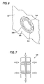
- FIG. 2 is a conceptual drawing in section of the micro-channel of FIG. 1 ;
- FIG. 3 is an exploded view in perspective making a sketch of a first mode of embodiment of the producing apparatus capable of being used in the present invention
- FIG. 4 is a schematic sectioned side elevation showing the mixing and separation of three liquids in the producing apparatus of FIG. 3 ;
- FIG. 5 is a partial perspective view showing the inflow side of a first plate constituting the producing apparatus of FIG. 3 ;
- FIG. 6 is a partial perspective view showing the inflow side of a second plate constituting the producing apparatus of FIG. 3 ;
- FIG. 7 is a schematic diagram showing a producing apparatus disposed vertically, and can be used in the present invention.
- FIG. 8 is a schematic perspective view of another mode of embodiment of the producing apparatus capable of being used in the present invention.
- the first method of producing a particle-dispersed liquid according to the present invention is a method of producing a particle-dispersed liquid, using micro-flow channels having a core flow channels, wherein the outer diameter of the outermost micro-flow channel is 50 to 5,000 ⁇ m, the method including the step of sending an indeterminately shaped particle-containing particle-dispersed liquid to a core flow channel on the inner side of the outermost core flow channel, and the step of separating and removing the indeterminately shaped particles from the particle-dispersed liquid and sending the resultant particles to the outermost core flow channel.
- the larger-diameter particles means components having larger particle diameters out of particles having particle diameter distribution, especially, particles the size of which is not smaller than 2.5 times as large as an average volume particle diameter Dv thereof.
- a Coulter Counter In order to measure the volume average particle diameter in the present invention, a Coulter Counter, TA-II type, (manufactured by Beckman Coulter, Inc.) can be used. When this counter is used, measurement is conducted by using an optimum aperture depending upon the particle diameter level of the particles. The diameter of the measured particles is expressed by an average volume diameter.
- the measurement is conducted by using a laser diffraction scattering type particle size measuring apparatus (LA-700, manufactured by Horiba Ltd.).
- LA-700 laser diffraction scattering type particle size measuring apparatus
- a second method of producing a particle-dispersed-liquid according to the present invention is a method of producing a particle-dispersed liquid, using micro-flow passages having core flow channels, wherein the outer diameter of the outermost micro-flow channel is 50 to 5,000 ⁇ m, the method including the step of sending an indeterminately shaped particle-containing particle-dispersed liquid to a core flow channel on the inner side of the outermost core flow passages, and the step of separating and removing the indeterminately shaped particles from the particle-dispersed liquid and sending the resultant particles to the outermost core flow channel.
- the indeterminately shaped particles mean particles of which the form factor SF1 is 20 or more larger than the average form factor SF1 thereof.
- the shape of the particles is defined by the form factor SF1.
- the form factor When this shape is close to a spherical shape, the form factor generally becomes 100 to 130, and, when the shape is indeterminate, the form factor exceeds 130.
- the particles the form factor of which is 20 or more larger than the average form factor thereof can be efficiently separated.
- the particles of which the form factor is larger by not smaller than 30 than the average form factor thereof can be more efficiently separated.
- the SF1 is defined as follows.
- ML represents an absolute maximum length of the particles
- A represents a projected area thereof.
- the inventors of the present invention discovered that, when larger particles existed in a particle-dispersed liquid or when indeterminately shaped particles existed therein, the particle-dispersed liquid was preferably sent to the channel on the inner side of the outermost core flow channels, and that the larger particles or indeterminately shaped particles were then separated and sent to the outermost core flow channel.
- the inventors further discovered that, when the particle-dispersed liquid was then taken out in a subsequent recovery unit from a recovery port the diameter of which is substantially equal to that of the port from which the particle-dispersed liquid was sent with the particle-dispersed liquid in the outermost channel taken from another recovery port, and that the larger particles and indeterminately shaped particles could be separated continuously with a high accuracy. It was discovered that a particle-dispersed liquid from which the larger particles and/or indeterminately shaped particles were removed in this manner could be produced.
- the particles are larger particles or have more indeterminate shapes, if not large, a sectional velocity of flow gradient perpendicular to the direction of the flow of the particles occurs in the core flow channels, so that the particles rotate. Therefore, it is considered that a force by which the particles move in the direction in which the velocity of flow is low occurs, and that the larger particles and indeterminately shaped particles move toward the wall surface.
- a recovery port of the flow channels of the particle-dispersed liquid is provided on the downstream side of the flow of the particles, a particle-dispersed liquid from which the larger particles or indeterminately shaped particles have been separated therefrom can be recovered.
- Dv denote the volume average diameter of the particles in the particle-dispersed liquid
- the Dv is preferably 0.1 ⁇ m to 1,000 ⁇ m, more preferably 0.1 ⁇ m to 500 ⁇ m, further more preferably 0.1 ⁇ m to 200 and, especially preferably 0.5 ⁇ m to 50 ⁇ m.
- volume average particle diameter of the particles is within these ranges, the influence of diffusion rarely occur, and the closure of the flow channels do not occur, so that preferable results are obtained.
- FIG. 1 shows an example of a conceptual diagram of micro-channel usable in the producing method according to the present invention.
- FIG. 1 is a conceptual diagram of a micro-flow passage in which two concentric flow channels are formed to separate larger particles and/or indeterminately shaped particles are separated.
- FIG. 2 is a conceptual diagram of the micro-channel taken along a cross section a-a′ in FIG. 1 .
- the micro-flow channel is provided with the outermost concentric flow channel 1 , and a flow channel 2 on the inner side of the outermost channel 1 .
- a particle-dispersed liquid A is supplied, and, in the outermost core channel, a larger particle and/or indeterminately-shaped particle-recovered fluid B (which will hereinafter be referred to as “recovered fluid B” as well).
- the velocity gradient 10 is conceptually shown in FIG. 1 . In the concentric flow, it is shown that the velocity of flow of the core portion is high, and that the velocity of flow lowers concentrically toward a wall surface portion.
- the outer diameter Lb of the outermost core flow channel is 50 to 5,000 ⁇ m, preferably 100 to 2000 ⁇ m, and more preferably 200 to 1,000 ⁇ m.
- the outer diameter of the outermost core flow channel is smaller than 50 ⁇ m, the closure and the like thereof occurs.
- this outer diameter exceeds 5,000 ⁇ m, a laminar flow is not stabilized, though it depends upon the velocity of flow, to cause problems to occur.
- the particle-dispersed liquid is supplied to the inner core flow channel rather than to the outermost core flow channel.
- the diameter La of the particle-dispersed liquid flow channel can be set freely in the range of smaller than Lb. However, when the diameter La of the particle-dispersed liquid flow channel is smaller than 10 times of the volume average diameter of the particles, the problem of the closure of the micro-flow channel may occur. On the other hand, when the diameter exceeds 4000 times as large as the volume average diameter of the particles, separation performance of the particles reduces at a center portion of the channel flow. Therefore, it is preferable that the diameter La of the particle-dispersed liquid flow channel is set to 10 to 4000 times larger than the volume average diameter of the particles contained in the particle-dispersed liquid. The diameter La is set more preferably to 30 to 4000 times larger than the volume average diameter, and further preferably 50 to 4000 times larger than the volume average diameter.
- the diameter La of the particle dispersed liquid flow passage can be determined on the basis of the observation using a microscope.
- the particle-dispersed liquid can be supplied to any of the layers on the inner side of the outermost core flow channel. It is preferable that the mentioned liquid be supplied from the outermost core flow channel to the adjacently inner side flow channel.
- the micro-channel has not smaller than 3 laminar flows, a core flow channel further exists in some cases on the inner side of the layer to which the particle-dispersed liquid is supplied.
- the above-mentioned La means the thickness of the layer to which the particle-dispersed liquid is supplied.
- the velocity of flow in the micro-passage is preferably 1 mm/s to 1,000 mm/s, and more preferably 10 mm/s to 100 mm/s. When the velocity of flow is within these ranges, the practicality thereof is high, and the laminar flow is stable, so that the velocity of flow is preferable.
- the velocity of flow can be determined by making calculation on the basis of the flow rate and diameter of the flow passage.
- the producing apparatus capable of being used in the present invention can be taken as an example an apparatus for producing a particle-dispersed liquid from which larger particles and/or indeterminately shaped particles have been separated and removed, the apparatus including a micro-channel having an introduction port into which the particle-dispersed liquid and a recovery liquid are introduced, a separation unit, a discharge port, and a recovery port for recovering separated larger particles and/or indeterminately formed particles. It is preferable that the particle-dispersed liquid introduction port be positioned on the upper side of the separation unit with respect to the gravitational direction, and that the recovery port be positioned on the lower side of the separation unit with respect to the gravitational direction. Positioning the introduction port and recovery port in this manner enables the flow passages to be stabilized, and is therefore, preferable.
- an angle between the flow channel and a direction of gravitational or buoyant force exceeds 45 degrees, the separation or discharge of the particles may not be sufficiently carried out due to sedimentation or floatation of the particles. Therefore, it is preferable to set the angle in a range of 0 to 45 degrees.
- the apparatus preferably used in the present invention is a micro-reactor, which has a plurality of micro-scale channels, for example, channels of a width of several to several thousand ⁇ m.
- the channels in the micro-reactor is micro-scales, so that both the dimensions and a velocity of flow are small, and a Reynold's number is not larger than 2,300. Therefore, the apparatus having channels of micro-scale is not turbulent flow dominant just as a regular apparatus but a laminar layer dominant.
- FIG. 3 is a development in perspective, a sketch of one mode of embodiment of the producing apparatus capable of being used in the present invention.
- FIG. 4 is a schematic sectioned side elevation showing three liquids mixed and separated in the producing apparatus shown in FIG. 3 .
- FIGS. 3 and 4 show a micro-reactor 330 constituting an apparatus for producing a particle-dispersed liquid, capable of being used in the present invention.
- the micro-reactor is a micro-reactor having channels of a width of several to several thousand ⁇ m as mentioned above.
- 3 liquids are set to a concentric laminar arrangement, to thereby form a 2-layer core flow channel.
- the 2-layer core flow channel is formed so that the diameter of the channel satisfies the La, Lb mentioned above.
- the micro-reactor 330 is provided with a first plate (core flow setting unit) 332 (refer to FIG. 5 as well), and a first cover member 334 and a mixing channel member (fluid mixing unit) 336 which are provided on the upstream side and downstream side respectively of the first plate 332 so as to sandwich the first plate 332 therebetween.
- the first plate 332 and first cover member 334 are formed detachably with respect to the micro-reactor.
- the core flow setting unit is adapted to send out the injected fluids as core flows the number of which corresponds to that of the kinds thereof.
- the shape of discharge ports of the core flow setting unit is not specially limited. Any shape of the discharge ports that permit outflow fluids to be set to core flow can be selected.
- the fluids flowing into the core flow setting unit 332 flow out there from concentrically, and flow into the fluid mixing unit 336 , in which the fluids are mixed. During this time, a flow rate, a velocity of flow, a fluid concentration and so forth of the fluids made to flow into the core flow setting unit are regulated, and the fluids are made to flow out concentrically as laminar flows.
- the first plate 332 is provided with a first fine channel 344 for turning the fluid flowing out from the pipes 20 A to 20 C into concentric layers.
- the particle-dispersed liquid A is introduced from the pipe 20 B, and larger particles and/or indeterminately shaped particle recovery fluid B (which will hereinafter be referred to as a recovery fluid as well) into the pipe 20 A or 20 C.
- the introduction of the particle-dispersed liquid A and the recovery fluid B be done under pressure by a micro-syringe, a rotary pump, a screw pump, a centrifugal pump and a piezo-pump and so forth.
- FIG. 5 is a partial perspective view showing an inflow side of the first plate constituting the producing apparatus of FIG. 3 .
- the first plate 332 is provided with a through hole 12 A extending from the first cover member and through the same plate.
- the inner diameter of the through hole 12 A is determined so that the fluid flows as a laminar flow (i.e., the Reynold's number becomes not larger than 2300) in the through hole 12 A.
- the through hole of the first cover member and that of the plate 12 A are formed to the same diameter so that a difference in level does not occur between the through hole of the first cover member and that 12 A of the plate.
- a cylindrical slit through hole 12 B is provided around the through hole 12 A of the first plate.
- the fluids sent from the introduction units 20 A, 20 C flow into the cylindrical slit through hole 12 B via a radial channel 13 B.
- the mixing channel member 336 is provided with a mixing channel 336 F adapted to simultaneously send two liquids flowing out from the first fine channel 344 , and the separation of the larger particles and/or indeterminately shaped particles in the particle-dispersed liquid progresses as the two liquids flowing out from the first fine channel 344 keep the core laminar flows.
- the micro-reactor 330 is further provided with a second plate (diversion unit) 337 (refer to FIG. 6 as well) disposed on the downstream side of the mixing channel member 336 , and a second cover member 339 sandwiching the second plate 337 between the mixing channel member 336 and the second cover member 339 .
- the second plate 337 and second cover member 339 are formed so as to be detachable with respect to the micro-reactor 330 .
- the second plate 337 is provided with a second fine channel 346 for separating and taking out a core side fluid 341 flowing on the channel core side and the outermost core side fluid 343 out of the fluids flowing out from the mixing channel 336 F as a laminar core current 340 .
- the second cover member 339 is provided with outflow channels 339 A, B, and C for sending out the core side fluid 341 and the outermost core current fluid 343 are sent out respectively.
- the particle-dispersed liquid discharged from 339 B is a liquid from which the larger particles and/or indeterminately shaped particles have been separated and removed.
- the separated larger particles and/or indeterminately shaped particles are discharged from the outflow channel 339 A or 339 C.
- FIG. 6 is a partial perspective view showing the inflow side of the second plate constituting the producing apparatus of FIG. 3 .
- the second plate 337 is provided as shown in FIG. 6 with an inflow port 348 into which a laminar core flow 340 moves freely, and an extraction partition plate unit 350 having a ring type extraction port 3501 in this inflow port 348 .
- a combination of the second cover member 339 and second plate 337 is of a specular surface symmetric type (symmetry of plane) with respect to a combination of the first plate 332 and cover member 334 . This enables the three liquids to be formed to two concentric laminar flows, and the concentric laminar flows 340 which have passed through the mixing channel 336 F to be separated into three liquids.
- the diameter (inner diameter of the extraction partition plate unit 350 ) of the central hole of the second plate 337 be set substantially equal to that of the central hole of the first plate 332 .
- the diameter of the central hole of the second plate is set slightly larger than that of the central hole of the first plate, a separation and recovery rate of the particles obtained from the core side fluid 341 constituting a material to be extracted can be improved.
- the diameter of the central hole of the second plate 337 is set slightly smaller than that of the central hole of the first plate 332 , the particle size distribution of the particles obtained from the core side fluid 341 can be rendered sharper and particles having low contents of larger particles and indeterminately shaped particles can be obtained.
- FIG. 7 is a schematic diagram showing a producing apparatus which is capable of being used in the present invention, and which is disposed vertically.
- An example in which the micro-reactor 330 is provided so that the mixing channel 336 F extends horizontally is shown in FIG. 4 .
- the micro-reactor 330 is provided so that the mixing channel 336 F extends vertically as shown in FIG. 7 , the disorder of the laminar concentric flows due to the gravity can be inhibited.
- fluids of which the gravity is greatly different are used, or when the dispersed particles are large, laminar concentric flows can be stably formed.
- the first cover member 334 , first plate 332 , mixing channel member 336 , second plate and second cover member 339 are joined together by screws, and a liquid leakage preventing O-ring is used.
- the assembling method is not limited to this, and a direct connecting method utilizing an intermolecular force of the surfaces of mutual members can also be used.
- a direct connecting method utilizing an intermolecular force of the surfaces of mutual members can also be used.
- the normal temperature direct connection techniques are effective in inhibiting the occurrence of thermal stress, which is ascribed to the difference in the linear expansion coefficients of the members, when the first plate 332 and first cover member 334 are made of different materials, and when the second plate 337 and second cover member 339 are made of different materials.
- the first plate is adapted to turn the laminar flow of 3 liquids into 2-layer concentric currents.
- the laminar flow of 3 liquids can also be turned into 3-layer concentric flows.
- the second fine channel 346 of the second plate 337 is selected suitably, the 3-layer concentric flow can also be separated.
- FIG. 8 is a development in perspective, a sketch of another mode of embodiment of the producing apparatus capable of being used in the present invention.
- FIG. 8 shows from the fluid introduction unit to the mixing channel member.
- the producing apparatus shown in FIG. 8 is capable of turning 2 sent liquids into 2-layer concentric flows conveniently.
- the producing apparatus (micro-rector) 400 has a pipe (introduction pipe) 410 for introducing a particle-dispersed liquid, and a pipe (introduction unit) 420 for introducing a recovery fluid into the micro-reactor.
- the pipe 410 for introducing the particle-dispersed liquid into the micro-reactor is directly connected to the cylindrical through pipe 430 , which extends through the first plate (concentric flow setting unit) 440 .
- the recovery fluid introduced by the pipe 420 into the micro-reactor is sent to the mixing channel member (liquid mixing unit) 460 through the fluid sending holes 450 A, B, C, and D provided in the first plate.
- the construction of the first plate is simple, and can be formed by a small number of members.
- the materials of which the producing apparatus according to the present invention can be formed are a metal, a ceramic material, a plastic material, glass and the like which are generally used, and these materials are preferably selected in a suitable manner in accordance with a medium liquid to be sent into the micro-reactor.
- the particle-dispersed liquid used in the present invention will be described.
- the medium liquid and particles of any specific gravity can be used. It is preferable that the particles be dispersed in the medium liquid with the specific gravity of the particles 0.87 to 21 times as large as that of the medium liquid, and more preferably 1.01 to 21 times as large as that of the medium liquid.
- the particles may be any of the resin particles, inorganic particles, metal particles, ceramic particles and the like.
- Paraffinic hydrocarbon which is solid at room temperature, such as solid paraffin can also be used as a material for forming particles.
- Particles of any specific gravity can be used.
- solid paraffin of specific gravity of about 0.9 and particles of polyethylene of specific gravity of 0.96 can also be used, and high molecular particles of specific gravity of not smaller than 1 can also be used.
- the particles include high molecular particles, crystals or aggregates of organisms, such as pigments, crystals or aggregates of inorganic substances, metal particles, or particles of metal compounds, such as metal oxides, metal sulfides and metal nitrides.
- the high molecular particles include concretely polyethylene, polyolefin, such as polypropylene, polyvinyl butyral resin, polyvinyl acetal resin, polyallylate resin, polycarbonate resin, polyester resin, phenoxy resin, polyvinyl chloride resin, polyvinylidene chloride resin, polyvinyl acetate resin, polystyrene resin, acrylic resin, methacrylic resin, styrene-acrylic resin, styrene-methacrylic resin, polyacrylamide resin, polyamide resin, polyvinyl pyridine resin, cellulose-based resin, polyurethane resin, epoxy resin, silicone resin, polyvinyl alcohol resin, casein, vinyl chloride-vinyl acetate copolymer, modified vinyl chloride-vinyl acetate copolymer, vinyl chloride-vinyl acetate-maleic-anhydride copolymer, styrene-butadiene copolymer, vinylidene chloride-acrylonit
- the particles of metals or metal compounds include metals, such as carbon black, zinc, aluminum, copper, iron, nickel, chromium, titanium, or alloys thereof, such as metal oxides, such as TiO 2 , SnO 2 , Sb 2 O 3 , In 2 O 3 , ZnO, MgO, metal oxides, such as ion oxide and compounds thereof, metal nitrides, such as silicon nitride or particles of combinations thereof.
- metals such as carbon black, zinc, aluminum, copper, iron, nickel, chromium, titanium, or alloys thereof, such as metal oxides, such as TiO 2 , SnO 2 , Sb 2 O 3 , In 2 O 3 , ZnO, MgO, metal oxides, such as ion oxide and compounds thereof, metal nitrides, such as silicon nitride or particles of combinations thereof.
- pulverized bodies particles produced by a dry type method
- the methods of dispersing dry pulverized bodies in a medium include a method using a sand mill, a colloid mill, an atoraita, a ball mill, a daino mill, a high-pressure homogenizer, a supersonic disperser, a coball mill, a roll mill and the like. It is preferable that this method be carried out under the condition that the primary particles are not pulverized by a dispersion operation.
- the specific gravity of the particles is preferably 0.87 to 21 times as large as that of the medium liquid mentioned above, and more 1.01 to 21 times as large as that of the same liquid.
- This specific gravity is further preferably 1.05 to 12 times as large as that of the medium liquid, and specially preferably 1.05 to 5 times as large as that thereof.
- the medium liquid is preferably a medium liquid having specific gravity of preferably 0.95 to 21 as large as that of the particles as mentioned above.
- the liquid medium is made of, for example, water, or a water-based medium, an organic solvent-based medium and the like, and preferably selected in a suitable manner.
- the water mentioned above includes ion exchange water, distilled water, electrolytic ionic water and the like.
- the organic solvent-based water includes concretely methanol, ethanol, n-propanol, n-butanol, benzyl alcohol, methyl cellosolve, ethyl cellosolve, acetone, methyl ethyl ketone, cyclo-hexanon, methyl acetate, acetate n-butyl, dioxane, tetrahydrofuran, methylene chloride, chloroform, chlorobenzene, toluen, xylene etc. and a mixture of not smaller than 2 kinds of these substances.
- a preferable medium liquid differs depending upon the kind of the particles.
- the preferable medium liquid for each kind of the particles are as follows.
- the medium liquids to be combined with the high molecular particles generally, having specific gravity of about 0.87 to about 1.6
- the medium liquids to be combined with particles (generally having specific gravity of about 2 to about 10) of a metal or a metal compound preferably include water, an organic solvent, such as alcohols, xylene etc. or oils which does not damage a metal by oxidation and reduction.
- More preferable combinations of particles with a medium liquid in the present invention include a combination of high molecular particles and a water-based medium, and a combination of a metal or a metal compound and a low-viscosity oil medium. Out of these combinations, the combination of high molecular particles and a water-based medium is specially preferable.
- Preferable combinations of particles with a medium liquid include a combination of styrene-acrylic particles and a water-based medium, a combination of styrene-methacrylic particles and a water-based medium, and a combination of polyester-based particles and a water-based medium.
- the content of the particles in the particle-dispersed liquid is preferably 0.1 to 60 vol. %, and more preferably 5 to 30 vol. %.
- the content of the particles in the particle-dispersed liquid is lower than 0.1 vol. %, the recovery of the particles becomes a problem in some cases, and, when this content exceeds 60 vol. %, the possibility that the channel be clogged therewith becomes high in some cases.
- the specific gravity of the particles can be measured by a vapor phase method (pyknometer method) using “Ultra-pyknometer 1000” manufactured by Yuasa-Ionics Co., Ltd.
- the specific gravity of the medium liquid can be measured by using “Specific Gravity Measuring Kit AD-1653” manufactured by A & D Co., Ltd.
- the recovered fluid is a fluid not containing particles. According to the present invention, it is preferable that the medium liquid and recovered fluid be the same liquid.
- the medium liquid be one of the medium liquids mentioned above as concrete examples.
- the preferable mode of the specific gravity of the recover fluid with respect to the recovered fluid is identical with that of the medium liquid with the particles.
- the water is used as the recovering fluid.
- the diameter Lb of the outermost core current channel is set to 500 ⁇ m, while the diameter La of the particle-dispersed channel is set to 250 ⁇ m.
- the velocity of flow is set to 15 mm/s.
- the length of the channel is set 300 mm, and the diameter of the recovery port for the particle-dispersed liquid to 250 ⁇ m.
- the sending of the liquid is done continuously for about 3 hours by using a micro-cylinder pump.
- the quantity of the larger particles of the particle-dispersed liquid recovered from the recovery port is measured to find out that the quantity is substantially 0%, and ascertain that the larger particles have been recovered in the larger particle recovering liquid.
- the deposition of the particles in the channel, and the indication of the blockade of the channel are not observed.
- the recovery rate of the particles is very high, and the recovery efficiency thereof is substantially 100%.
- the sending of liquid is done in the same manner as in the embodiment 1 except that the particle-dispersed liquid A1 in the embodiment 1 is changed to the particle-dispersed liquid A2.
- the content of the indeterminately shaped particles in the particle-dispersed liquid recovered from the particle-dispersed liquid recovery port is measured to find out that the content is substantially 0%. Furthermore, the indication of the deposition of particles in the channel and the closure of the channel is not observed. The recovery rate of the particles is also substantially 100%, so that the particle recovery efficiency is extremely high.
- the larger particles in a particle-dispersed liquid can be separated and removed therefrom with a high accuracy. Furthermore, the indeterminately shaped particles in a particle-dispersed liquid can be separated and removed therefrom. These particle separating and removing operations can be carried out continuously.
- the deposition of particles on a wall surface and the coagulation of the particles do not occur, so that the closure of the flow passages due to the particles do not occur. Therefore, larger particles and indeterminately shaped particles can be separated and removed from a particle-dispersed liquid with a high separation efficiency.
Abstract
Description
Re=uL/ν
Claims (16)
Applications Claiming Priority (2)
| Application Number | Priority Date | Filing Date | Title |
|---|---|---|---|
| JP2005184518A JP4835047B2 (en) | 2005-06-24 | 2005-06-24 | Method for producing fine particle dispersion |
| JP2005-184518 | 2005-06-24 |
Publications (2)
| Publication Number | Publication Date |
|---|---|
| US20070007220A1 US20070007220A1 (en) | 2007-01-11 |
| US7648033B2 true US7648033B2 (en) | 2010-01-19 |
Family
ID=37137508
Family Applications (1)
| Application Number | Title | Priority Date | Filing Date |
|---|---|---|---|
| US11/236,824 Expired - Fee Related US7648033B2 (en) | 2005-06-24 | 2005-09-28 | Method of producing particle-dispersed liquid |
Country Status (3)
| Country | Link |
|---|---|
| US (1) | US7648033B2 (en) |
| EP (1) | EP1736226B1 (en) |
| JP (1) | JP4835047B2 (en) |
Families Citing this family (4)
| Publication number | Priority date | Publication date | Assignee | Title |
|---|---|---|---|---|
| JP5040876B2 (en) * | 2008-09-25 | 2012-10-03 | 富士ゼロックス株式会社 | Separation method and separation apparatus |
| FR2938252B1 (en) * | 2008-11-07 | 2014-08-22 | Otv Sa | METHOD OF TREATING WATER INVOLVING FILTRATION THROUGH AT LEAST ONE IMMERED MEMBRANE |
| JP5636652B2 (en) * | 2009-08-21 | 2014-12-10 | 富士ゼロックス株式会社 | Classification device and classification method |
| CN106536709A (en) * | 2014-06-16 | 2017-03-22 | 基纽拜奥股份有限公司 | Size alternating injection into drops to facilitate sorting |
Citations (8)
| Publication number | Priority date | Publication date | Assignee | Title |
|---|---|---|---|---|
| DE4017709A1 (en) | 1990-06-01 | 1991-12-05 | Tibor Dr Zoeld | Rapid division of fluid stream - for fluid distribution or sorting of suspended particles, esp. cells |
| US5076943A (en) * | 1984-09-10 | 1991-12-31 | Rakow Allen L | Fluid particle separator with pressure drop resistance matching |
| US5089126A (en) * | 1989-03-31 | 1992-02-18 | Lehigh University | Method and apparatus for capillary hydrodynamic fractionation |
| EP0641587A2 (en) | 1993-08-27 | 1995-03-08 | Bayer Ag | Process for separating dispersions of particles in liquids in a particle-rich and a particle poor part |
| WO2002029400A2 (en) | 2000-09-30 | 2002-04-11 | Aviva Biosciences Corporation | Apparatuses and methods for field flow fractionation of particles using acoustic and other forces |
| US20040213083A1 (en) | 2003-04-28 | 2004-10-28 | Fuji Photo Film Co., Ltd. | Fluid mixing apparatus and fluid mixing system |
| US20070000814A1 (en) * | 2005-06-15 | 2007-01-04 | Shot, Inc. | Continuous particle separation apparatus |
| US7328807B2 (en) * | 2004-09-22 | 2008-02-12 | Fuji Xerox Co., Ltd. | Method and device for classifying fine particles |
Family Cites Families (3)
| Publication number | Priority date | Publication date | Assignee | Title |
|---|---|---|---|---|
| JP2004154747A (en) * | 2002-11-02 | 2004-06-03 | Minoru Seki | Continuous particle separation mechanism and apparatus for the same |
| JP2005205387A (en) * | 2004-01-24 | 2005-08-04 | Minoru Seki | Continuous particle classification method |
| JP4992201B2 (en) * | 2005-06-07 | 2012-08-08 | 富士ゼロックス株式会社 | Microfluidic control method, microfluidic device and manufacturing method thereof |
-
2005
- 2005-06-24 JP JP2005184518A patent/JP4835047B2/en not_active Expired - Fee Related
- 2005-09-28 US US11/236,824 patent/US7648033B2/en not_active Expired - Fee Related
- 2005-10-10 EP EP05022054A patent/EP1736226B1/en not_active Expired - Fee Related
Patent Citations (8)
| Publication number | Priority date | Publication date | Assignee | Title |
|---|---|---|---|---|
| US5076943A (en) * | 1984-09-10 | 1991-12-31 | Rakow Allen L | Fluid particle separator with pressure drop resistance matching |
| US5089126A (en) * | 1989-03-31 | 1992-02-18 | Lehigh University | Method and apparatus for capillary hydrodynamic fractionation |
| DE4017709A1 (en) | 1990-06-01 | 1991-12-05 | Tibor Dr Zoeld | Rapid division of fluid stream - for fluid distribution or sorting of suspended particles, esp. cells |
| EP0641587A2 (en) | 1993-08-27 | 1995-03-08 | Bayer Ag | Process for separating dispersions of particles in liquids in a particle-rich and a particle poor part |
| WO2002029400A2 (en) | 2000-09-30 | 2002-04-11 | Aviva Biosciences Corporation | Apparatuses and methods for field flow fractionation of particles using acoustic and other forces |
| US20040213083A1 (en) | 2003-04-28 | 2004-10-28 | Fuji Photo Film Co., Ltd. | Fluid mixing apparatus and fluid mixing system |
| US7328807B2 (en) * | 2004-09-22 | 2008-02-12 | Fuji Xerox Co., Ltd. | Method and device for classifying fine particles |
| US20070000814A1 (en) * | 2005-06-15 | 2007-01-04 | Shot, Inc. | Continuous particle separation apparatus |
Non-Patent Citations (2)
| Title |
|---|
| Ogawara et al. "Discussion of Behavior in a Micro-Separation Classification Apparatus by Euler-Lagrange Method." 69th-year Collection of Manuscripts of the Academic Circle of the Chemical Engineering. No. 202. 2004. |
| Seki et al. "Development of a Method of ContinuouslyClassifying Fine Particles Using Micro-Channel Layer Flow System." 69th-year Collection of Manuscripts of the Academic Circle of the Chemical Engineering. No. 201. 2004. |
Also Published As
| Publication number | Publication date |
|---|---|
| JP2007000786A (en) | 2007-01-11 |
| JP4835047B2 (en) | 2011-12-14 |
| EP1736226B1 (en) | 2011-05-25 |
| EP1736226A1 (en) | 2006-12-27 |
| US20070007220A1 (en) | 2007-01-11 |
Similar Documents
| Publication | Publication Date | Title |
|---|---|---|
| JP4462058B2 (en) | Fine particle classification method and fine particle classification device | |
| Yoon et al. | Integrated vertical screen microfilter system using inclined SU-8 structures | |
| SA08290648B1 (en) | Fluidic Device and Method for Separation of Neutrally Buoyant Particles | |
| JP2010201549A (en) | Microchannel device, separation method, and separator | |
| US7648033B2 (en) | Method of producing particle-dispersed liquid | |
| US20100072116A1 (en) | Classifying device and method of classification | |
| US8226332B2 (en) | Liquid transporting method and classifying method | |
| EP1595597B1 (en) | Method for delivering a fine particle dispersion | |
| US7572375B2 (en) | Method and device for treating fine particles | |
| JP2012239991A (en) | Device for classifying fine particle | |
| US20090236269A1 (en) | Classification method and classification apparatus | |
| JP5636652B2 (en) | Classification device and classification method | |
| JP4915426B2 (en) | Classification method and classification device | |
| US8087515B2 (en) | Separation method and separation apparatus | |
| JP6273510B2 (en) | Liquid feeding method, centrifugal separation method, liquid feeding device and centrifugal separator | |
| Ohmura et al. | Particle classification in Taylor vortex flow with an axial flow | |
| JP4461941B2 (en) | Method for feeding fine particle dispersion and liquid feeding device for fine particle dispersion | |
| JP2000301022A (en) | Wet classifier and wet classifying method | |
| Rodgers | Solids Processing | |
| JP3382752B2 (en) | Wet classification apparatus and wet classification method | |
| Lee et al. | Inertial microfluidics and its applications in hematology | |
| Di Carlo et al. | INERTIAL MICROFLUIDICS: HIGH-THROUGHPUT FOCUSING AND SEPARA-TION OF CELLS AND PARTICLES | |
| Tai et al. | Streamline-based microfluidic device | |
| JP2010075882A (en) | Microchannel apparatus and classification method | |
| Kalita | A Microparticle Separation Device Using Inertia Combined Dielectrophoresis Technique for the Separation of Tumour Cells from Blood |
Legal Events
| Date | Code | Title | Description |
|---|---|---|---|
| AS | Assignment |
Owner name: FUJI XEROX CO., LTD., JAPAN Free format text: ASSIGNMENT OF ASSIGNORS INTEREST;ASSIGNORS:TAKAGI, SEIICHI;OHTA, TETSUO;REEL/FRAME:017039/0882 Effective date: 20050921 |
|
| STCF | Information on status: patent grant |
Free format text: PATENTED CASE |
|
| AS | Assignment |
Owner name: NATIONAL INSTITUTES OF HEALTH (NIH), U.S. DEPT. OF Free format text: CONFIRMATORY LICENSE;ASSIGNOR:NEW MEXICO STATE UNIVERSITY;REEL/FRAME:026328/0697 Effective date: 20050923 |
|
| FPAY | Fee payment |
Year of fee payment: 4 |
|
| FPAY | Fee payment |
Year of fee payment: 8 |
|
| FEPP | Fee payment procedure |
Free format text: MAINTENANCE FEE REMINDER MAILED (ORIGINAL EVENT CODE: REM.); ENTITY STATUS OF PATENT OWNER: LARGE ENTITY |
|
| LAPS | Lapse for failure to pay maintenance fees |
Free format text: PATENT EXPIRED FOR FAILURE TO PAY MAINTENANCE FEES (ORIGINAL EVENT CODE: EXP.); ENTITY STATUS OF PATENT OWNER: LARGE ENTITY |
|
| STCH | Information on status: patent discontinuation |
Free format text: PATENT EXPIRED DUE TO NONPAYMENT OF MAINTENANCE FEES UNDER 37 CFR 1.362 |
|
| FP | Lapsed due to failure to pay maintenance fee |
Effective date: 20220119 |