US7643697B2 - Accelerative noise filtering method for image data - Google Patents
Accelerative noise filtering method for image data Download PDFInfo
- Publication number
- US7643697B2 US7643697B2 US11/505,550 US50555006A US7643697B2 US 7643697 B2 US7643697 B2 US 7643697B2 US 50555006 A US50555006 A US 50555006A US 7643697 B2 US7643697 B2 US 7643697B2
- Authority
- US
- United States
- Prior art keywords
- pixel
- value
- pixels
- target pixel
- neighboring
- Prior art date
- Legal status (The legal status is an assumption and is not a legal conclusion. Google has not performed a legal analysis and makes no representation as to the accuracy of the status listed.)
- Expired - Lifetime, expires
Links
Images


Classifications
-
- G—PHYSICS
- G06—COMPUTING OR CALCULATING; COUNTING
- G06T—IMAGE DATA PROCESSING OR GENERATION, IN GENERAL
- G06T5/00—Image enhancement or restoration
- G06T5/70—Denoising; Smoothing
-
- G—PHYSICS
- G06—COMPUTING OR CALCULATING; COUNTING
- G06T—IMAGE DATA PROCESSING OR GENERATION, IN GENERAL
- G06T5/00—Image enhancement or restoration
- G06T5/20—Image enhancement or restoration using local operators
-
- G—PHYSICS
- G06—COMPUTING OR CALCULATING; COUNTING
- G06T—IMAGE DATA PROCESSING OR GENERATION, IN GENERAL
- G06T2207/00—Indexing scheme for image analysis or image enhancement
- G06T2207/20—Special algorithmic details
- G06T2207/20004—Adaptive image processing
- G06T2207/20012—Locally adaptive
Definitions
- the present invention relates to a technology for processing image data. More particularly, the present invention relates to a method to for effectively and rapidly filtering noise generated when obtaining and coding image data.
- the median filter is a nonlinear recovering technology, which is designed to filter impulse type noises from the image, while preserving the edge.
- the two-dimensional median filter uses a 3 ⁇ 3 or 5 ⁇ 5 rectangular mask to enclose the pixel to be filtered.
- the gray level of each pixel is replaced by the median of the gray levels in a neighborhood of that pixel, instead of by average.
- the median of a set of values is such that half the values in the set are less than m and half are greater than m.
- the values of the pixel and its neighbors are sorted to determine the median, and assign this value to the pixel.
- MTM filters are a combination of the median filter and mean value filter. Consequently, they can overcome the disadvantage of the median filter and improving the noise suppressing effect.
- the median is first derived.
- the mean value filter is then applied on the pixel having a value near it as the object, and the result is output.
- a topic to be solved is how to set the object range of the mean value filter in consideration of the characteristics of the image. Also, it has been pointed out that, compared with the conventional median filter, the edge portion becomes more blurred.
- FMH filters are also a combination of the median filter and the mean value filter.
- FMH filters differ from MTM filters in that a mean value filter is applied first.
- the mask for the mean value filter has a directionality with quantization in 90° or 450°. Compared with MTM filters, they can suppress blurriness of the edge portion, and the amount of computation required can be reduced significantly.
- the edge preserving smoothing filter is a type of selective smoothing filter. It performs adaptive switching of the mask according to the localized properties of the region. Several types of polygonal masks are initially defined. Then, the degree of the variation in the pixel value in the region corresponding to each mask is calculated. Then, among the masks, the mask with the smallest degree of variation of the pixel value is selected, and the mean value of the pixel value in the region corresponding to this mask is output. In this case, the noise can be suppressed while the edge is preserved. However, it has been pointed out that the fine texture is lost, which is a disadvantage.
- the above conventional technologies utilize the mean value of the pixel values in the region corresponding to a mask the target pixel centered as the output of the target pixel.
- One of the known method for obtaining the mean value includes selecting eight neighboring pixels x, y, z, a, c, d, e, f around a target pixel b, i.e. the pixel to be filtered, and calculating an absolute value of a difference between the target pixel and each of the eight neighboring pixels.
- the absolute value of the difference between the target pixel and one of the eight neighboring pixels is larger than a standard deviation, the neighboring pixel is abandoned, not putted in the mean value filtering computation.
- the neighboring pixel is putted in the mean value filtering computation.
- b′ average(xyzabcdef)
- b′ average(xyzb)
- the divisor of each of the pixel values putted in the noise filtering computation is 9.
- the noise filtering computation would be complicated whether implemented using hardware, software or a combination of hardware and software, and consume much time.
- the selected neighboring pixels are putted in a noise filtering computation to obtain a new pixel value for replacing the target pixel.
- the noise filtering process of image data is thus simplified and accelerated.
- the present invention provides an accelerative noise filtering method for image data.
- Image data are provided and a pixel to be filtered as a target pixel is selected from the image data. Then, selecting four neighboring pixels around the target pixel in a pattern of a cross shape or X shape from the image data. Calculating an absolute value of a difference between the target pixel and each of the four neighboring pixels.
- X 0 represents the target pixel value and X 0 ′ represents the new pixel value
- X 2 is the neighboring pixel value preceding the target pixel value X 0
- X 3 is the neighboring pixel value following the target pixel value X 0
- the present method for noise reduction substitutes a target pixel with a weighted average of the target pixel itself and four neighboring pixels around it in a pattern of a cross shape or X shape according to the degree of similarity between the target pixel and the neighboring pixels.
- the noise filtering computation of the present method is thus significantly simplified and the computation is accelerated.
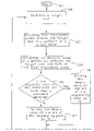
- FIGS. 1A and 1B are a flow diagram of a noise filtering process according to one preferred embodiment of the present invention.
- FIG. 2A is a diagram illustrating an example of selection of a mask of the preferred embodiment of FIGS. 1A and 1B ;
- FIG. 2B is a diagram illustrating an example of selection of a mask of another preferred embodiment of the present invention.
- FIG. 3 is a mapping table (I) illustrating possible cases applied in the present noise filtering method.
- FIG. 4 is a mapping table (II) illustrating possible weightings of neighboring pixels around a target pixel utilized in a noise filtering computation of the present invention.
- the present invention provides an accelerative noise filtering method, which selects neighboring pixels of a target pixel, i.e. the pixel to be filtered, among four neighboring pixels around the target pixel in a pattern of a cross shape or X shape according to the degree of similarity between the target pixel and the neighboring pixels. Then, the selected neighboring pixels are putted into a noise filtering computation to obtain a new pixel value for replacing the target pixel value.
- the new pixel value is a weighted average of the pixel values of the target pixel and the selected neighboring pixels.
- FIGS. 1A and 1B depict a flow diagram illustrating a noise filtering method according to one preferred embodiment of the present invention.
- the noise filtering method of the preferred embodiment begins at step 101 .
- image data are provided and a target pixel P 0 , i.e. a pixel to be filtered, is selected from the image data.
- a target pixel P 0 i.e. a pixel to be filtered
- step 103 referring to FIG. 2A , four neighboring pixels P 1 , P 2 , P 3 , P 4 around the target pixel P 0 in a pattern of a cross shape is selected.
- the neighboring pixel P 1 belongs to a scan line preceding the scan line the target pixel P 0 belongs to.
- the neighboring pixels P 2 and P 3 belong to the same scan line with the target pixel P 0 .
- the neighboring pixel P 2 precedes the target pixel P 0 and the neighboring pixel P 3 follows the target pixel P 0 .
- the neighboring pixel P 4 belongs to a scan line follows the scan line the target pixel P 0 belongs to.
- step 104 calculating an absolute value of a difference between the target pixel P 0 and each of the four neighboring pixels P 1 , P 2 , P 3 and P 4 .
- step 105 Comparing the absolute value of the difference between the target pixel P 0 and any of the neighboring pixels P 1 , P 2 , P 3 and P 4 with a standard deviation.
- step 106 setting a binary value of a bit corresponding to the neighboring pixel as “1”.
- step 107 setting a binary value of a bit corresponding to the neighboring pixel as “0”.
- step 108 establishing a 4-bit mapping table including the binary values of the neighboring pixels P 1 , P 2 , P 3 and P 4 in accordance with the result generated from step 105 through 107 .
- table (I) shown in FIG. 3 the 4-bit mapping table established by step 105 through 107 is matched with one case shown in the table (I). That is, the 4-bit condition of the four neighboring pixels P 1 , P 2 , P 3 and P 4 can map to any one of the sixteen cases, case 0 through 15 , shown in table (I).
- step 109 a calculation (I) shown in the following is derived from the 4-bit mapping table:
- X 0 represents the target pixel value and X 0 ′ represents a new is pixel value for replacing the target pixel value X 0
- the weighting coefficient of both of the target pixel and the neighboring pixel is the value of 1 ⁇ 2, see cases 1 , 2 , 4 , and 8 .
- the weighting coefficient of both of the two neighboring pixels is the value of to 1 ⁇ 4 and the weighting coefficient of the target pixel is the value of 1 ⁇ 2, see cases 3 , 5 , 6 , 9 , 10 , 12 and 13 .
- the two neighboring pixels P 2 and P 3 among the three neighboring pixels P 2 , P 3 and P 4 are selected, and the weighting coefficient of the two neighboring pixels P 2 and P 3 is the value of 1 ⁇ 4.
- the target pixel has a weighting coefficient of 1 ⁇ 2 in the case 7 .
- the pixels easily become blurred aligning the direction of the movement of a stepping motor used for moving a scanning head.
- the target pixel has a weighting coefficient of 1 ⁇ 2 in the case 11 .
- the weighting coefficient of each of the two neighboring pixels P 1 and P 2 is the value of 1 ⁇ 4.
- the target pixel has a weighting coefficient of 1 ⁇ 2 in the case 14 .
- step 110 calculating a new pixel value X 0 ′ based on the calculation (I) derived from the 4-bit mapping table.
- the weighting coefficients of the target pixel and the four neighboring pixels are obtained from the 4-bit mapping table.
- the new pixel value X 0 ′ is replaced for the target pixel value X 0 .
- step 111 determining if the noise filtering computation is going to be performed for a next pixel? If it is yes, go to step 112 , shifting to the next pixel, and repeating step 102 through 111 . If it is not, go to step 113 , completing the noise filtering computation.
- the present invention can only use the module of shift and adder in hardware to perform the noise filtering process.
- the complexity of the hardware used therefor is significantly reduced, and the computation time of the present method whether implemented by hardware, software or in a combination of hardware and software is much shorter.
- the four neighboring pixels P 1 , P 2 , P 3 and P 4 around the target pixel P 0 in an X-shaped pattern are selected.
- the noise filtering process is the same with that depicted in FIGS. 1A and 1B . That is, step 101 through 113 is repeated in this preferred embodiment.
Landscapes
- Physics & Mathematics (AREA)
- General Physics & Mathematics (AREA)
- Engineering & Computer Science (AREA)
- Theoretical Computer Science (AREA)
- Image Processing (AREA)
Abstract
Description
wherein X0 represents the target pixel value and X0′ represents the new pixel value, X1 (i=1˜4) represents the pixel value of one of the four neighboring pixels, X1 belonging to a scan line preceding the scan line the target pixel value X0 belonging to, X2 and X3 belonging to the same scan line with the target pixel value X0, X2 is the neighboring pixel value preceding the target pixel value X0 and X3 is the neighboring pixel value following the target pixel value X0, and X4 belonging to a scan line following the scan line the target pixel value X0 belonging to, Ki (i=0˜4) is a weighting coefficient of one of the four neighboring pixels and the target pixel, when the binary value of the neighboring pixel is set as “0”, the weighting coefficient Ki thereof is set zero, and the neighboring pixels having the binary value “1” are provided with equivalent weighting coefficients. The present method for noise reduction substitutes a target pixel with a weighted average of the target pixel itself and four neighboring pixels around it in a pattern of a cross shape or X shape according to the degree of similarity between the target pixel and the neighboring pixels. The noise filtering computation of the present method is thus significantly simplified and the computation is accelerated.
wherein X0 represents the target pixel value and X0′ represents a new is pixel value for replacing the target pixel value X0, X1 (i=1˜4) represents one pixel value of one neighboring pixel Pi (i=1˜4) among the four neighboring pixels P1, P2, P3 and P4. K1 (i=0˜4) is a weighting coefficient of one of the four neighboring pixels and the target pixel. When the binary value of the neighboring pixel P1 is set as “0”, the weighting coefficient K1 thereof is set zero, and the neighboring pixels among the four neighboring pixels having the binary value “1” are provided with equivalent weighting coefficients. Referring to table (II) shown in
Claims (18)
Priority Applications (1)
| Application Number | Priority Date | Filing Date | Title |
|---|---|---|---|
| US11/505,550 US7643697B2 (en) | 2002-09-27 | 2006-08-16 | Accelerative noise filtering method for image data |
Applications Claiming Priority (2)
| Application Number | Priority Date | Filing Date | Title |
|---|---|---|---|
| US10/255,965 US7203378B2 (en) | 2002-09-27 | 2002-09-27 | Accelerative noise filtering method for image data |
| US11/505,550 US7643697B2 (en) | 2002-09-27 | 2006-08-16 | Accelerative noise filtering method for image data |
Related Parent Applications (1)
| Application Number | Title | Priority Date | Filing Date |
|---|---|---|---|
| US10/255,965 Continuation US7203378B2 (en) | 2002-09-27 | 2002-09-27 | Accelerative noise filtering method for image data |
Publications (2)
| Publication Number | Publication Date |
|---|---|
| US20060285765A1 US20060285765A1 (en) | 2006-12-21 |
| US7643697B2 true US7643697B2 (en) | 2010-01-05 |
Family
ID=32029202
Family Applications (2)
| Application Number | Title | Priority Date | Filing Date |
|---|---|---|---|
| US10/255,965 Expired - Lifetime US7203378B2 (en) | 2002-09-27 | 2002-09-27 | Accelerative noise filtering method for image data |
| US11/505,550 Expired - Lifetime US7643697B2 (en) | 2002-09-27 | 2006-08-16 | Accelerative noise filtering method for image data |
Family Applications Before (1)
| Application Number | Title | Priority Date | Filing Date |
|---|---|---|---|
| US10/255,965 Expired - Lifetime US7203378B2 (en) | 2002-09-27 | 2002-09-27 | Accelerative noise filtering method for image data |
Country Status (1)
| Country | Link |
|---|---|
| US (2) | US7203378B2 (en) |
Families Citing this family (12)
| Publication number | Priority date | Publication date | Assignee | Title |
|---|---|---|---|---|
| US7215824B2 (en) * | 2002-09-10 | 2007-05-08 | Chui-Kuei Chiu | Method for adjusting image data with shading curve |
| US7613363B2 (en) * | 2005-06-23 | 2009-11-03 | Microsoft Corp. | Image superresolution through edge extraction and contrast enhancement |
| KR100735561B1 (en) * | 2005-11-02 | 2007-07-04 | 삼성전자주식회사 | Method and apparatus for reducing noise generated from image sensor |
| TWI324013B (en) * | 2006-02-22 | 2010-04-21 | Huper Lab Co Ltd | Video noise reduction method using adaptive spatial and motion-compensation temporal filters |
| EP1868369B1 (en) * | 2006-06-12 | 2013-08-21 | STMicroelectronics (Research & Development) Limited | Digital filter |
| EP2070042A2 (en) * | 2006-09-29 | 2009-06-17 | THOMSON Licensing | Automatic parameter estimation for adaptive pixel-based filtering |
| JP5047005B2 (en) * | 2008-02-29 | 2012-10-10 | キヤノン株式会社 | Image processing method, pattern detection method, pattern recognition method, and image processing apparatus |
| TWI413023B (en) * | 2010-03-30 | 2013-10-21 | Novatek Microelectronics Corp | Method and apparatus for motion detection |
| TWI488494B (en) * | 2011-04-28 | 2015-06-11 | Altek Corp | Method of multi-frame image noise reduction |
| JP6320053B2 (en) * | 2014-01-22 | 2018-05-09 | キヤノン株式会社 | Image processing apparatus, image processing method, and computer program |
| US9262810B1 (en) * | 2014-09-03 | 2016-02-16 | Mitsubishi Electric Research Laboratories, Inc. | Image denoising using a library of functions |
| CN111507923B (en) * | 2020-04-21 | 2023-09-12 | 浙江大华技术股份有限公司 | Noise processing method, device, equipment and medium for video image |
Citations (7)
| Publication number | Priority date | Publication date | Assignee | Title |
|---|---|---|---|---|
| US5550936A (en) * | 1991-08-23 | 1996-08-27 | Mitsubishi Denki Kabushiki Kaisha | Image processing system |
| US5663764A (en) | 1993-09-30 | 1997-09-02 | Sony Corporation | Hierarchical encoding and decoding apparatus for a digital image signal |
| US5959693A (en) | 1997-05-07 | 1999-09-28 | General Instrument Corporation | Pixel adaptive noise reduction filter for digital video |
| US6094511A (en) * | 1996-07-31 | 2000-07-25 | Canon Kabushiki Kaisha | Image filtering method and apparatus with interpolation according to mapping function to produce final image |
| US6151410A (en) | 1996-11-19 | 2000-11-21 | Seiko Epson Corporation | Image processing apparatus, image processing method and medium for storing image-processing control program |
| US6332136B1 (en) * | 1996-12-11 | 2001-12-18 | Sgs-Thomson Microelectronics S.R.L. | Fuzzy filtering method and associated fuzzy filter |
| US20030021489A1 (en) | 2001-07-24 | 2003-01-30 | Seiko Epson Corporation | Image processor and image processing program, and image processing method |
-
2002
- 2002-09-27 US US10/255,965 patent/US7203378B2/en not_active Expired - Lifetime
-
2006
- 2006-08-16 US US11/505,550 patent/US7643697B2/en not_active Expired - Lifetime
Patent Citations (7)
| Publication number | Priority date | Publication date | Assignee | Title |
|---|---|---|---|---|
| US5550936A (en) * | 1991-08-23 | 1996-08-27 | Mitsubishi Denki Kabushiki Kaisha | Image processing system |
| US5663764A (en) | 1993-09-30 | 1997-09-02 | Sony Corporation | Hierarchical encoding and decoding apparatus for a digital image signal |
| US6094511A (en) * | 1996-07-31 | 2000-07-25 | Canon Kabushiki Kaisha | Image filtering method and apparatus with interpolation according to mapping function to produce final image |
| US6151410A (en) | 1996-11-19 | 2000-11-21 | Seiko Epson Corporation | Image processing apparatus, image processing method and medium for storing image-processing control program |
| US6332136B1 (en) * | 1996-12-11 | 2001-12-18 | Sgs-Thomson Microelectronics S.R.L. | Fuzzy filtering method and associated fuzzy filter |
| US5959693A (en) | 1997-05-07 | 1999-09-28 | General Instrument Corporation | Pixel adaptive noise reduction filter for digital video |
| US20030021489A1 (en) | 2001-07-24 | 2003-01-30 | Seiko Epson Corporation | Image processor and image processing program, and image processing method |
Also Published As
| Publication number | Publication date |
|---|---|
| US20060285765A1 (en) | 2006-12-21 |
| US7203378B2 (en) | 2007-04-10 |
| US20040062449A1 (en) | 2004-04-01 |
Similar Documents
| Publication | Publication Date | Title |
|---|---|---|
| US7643697B2 (en) | Accelerative noise filtering method for image data | |
| Schulte et al. | A fuzzy impulse noise detection and reduction method | |
| Morillas et al. | Fuzzy peer groups for reducing mixed Gaussian-impulse noise from color images | |
| JP3549720B2 (en) | Image processing device | |
| US7373020B2 (en) | Image processing apparatus and image processing program | |
| US6681054B1 (en) | Noise reduction method utilizing probabilistic weighting, apparatus, and program for digital image processing | |
| US6718068B1 (en) | Noise reduction method utilizing statistical weighting, apparatus, and program for digital image processing | |
| US6621937B1 (en) | Removing chroma noise from digital images by using variable shape pixel neighborhood regions | |
| US7894110B2 (en) | Pixel interpolation method and image distinction method | |
| Kim et al. | Multiple level feature-based universal blind image quality assessment model | |
| JP4251189B2 (en) | Image data conversion processing apparatus and image data conversion processing method | |
| KR20030096438A (en) | Picture encoder, picture decoder, picture encoding method, picture decoding method, and medium | |
| US20050244052A1 (en) | Edge-sensitive denoising and color interpolation of digital images | |
| WO2008018331A1 (en) | Method, apparatus and integrated circuit capable of reducing image ringing noise | |
| EP0613290B1 (en) | Method and apparatus for binary image data compression | |
| US4841377A (en) | Continuous image estimation method | |
| US5960119A (en) | Method of and system for encoding digital images | |
| US20060119896A1 (en) | Image processing apparatus, image processing program, electronic camera, and image processing method for smoothing image of mixedly arranged color components | |
| JP4235162B2 (en) | Image encoding apparatus, image encoding method, image encoding program, and computer-readable recording medium | |
| JPH0944128A (en) | Multilevel reduction processor for binary picture | |
| JP3798150B2 (en) | Image processing method and image processing apparatus | |
| JPH11331615A (en) | Image compression device | |
| US7123776B2 (en) | Method of processing digital images for low-bit rate applications | |
| JPH07307942A (en) | Image noise eliminator | |
| Azimi-Sadjadi et al. | Neural network decision directed edge-adaptive Kalman filter for image estimation |
Legal Events
| Date | Code | Title | Description |
|---|---|---|---|
| AS | Assignment |
Owner name: TRANSPACIFIC IP, LTD., TAIWAN Free format text: ASSIGNMENT OF ASSIGNORS INTEREST;ASSIGNOR:VEUTRON CORPORATION;REEL/FRAME:018210/0402 Effective date: 20050706 Owner name: VEUTRON CORPORATION, TAIWAN Free format text: CHANGE OF NAME;ASSIGNOR:UMAX DATA SYSTEMS INC.;REEL/FRAME:018208/0116 Effective date: 20021029 Owner name: UMAX DATA SYSTEMS, INC., TAIWAN Free format text: ASSIGNMENT OF ASSIGNORS INTEREST;ASSIGNOR:CHIU, CHUI-KUEI;REEL/FRAME:018190/0077 Effective date: 20020910 |
|
| AS | Assignment |
Owner name: TRANSPACIFIC SYSTEMS, LLC, DELAWARE Free format text: ASSIGNMENT OF ASSIGNORS INTEREST;ASSIGNOR:TRANSPACIFIC IP LTD.;REEL/FRAME:023107/0267 Effective date: 20090618 Owner name: TRANSPACIFIC SYSTEMS, LLC,DELAWARE Free format text: ASSIGNMENT OF ASSIGNORS INTEREST;ASSIGNOR:TRANSPACIFIC IP LTD.;REEL/FRAME:023107/0267 Effective date: 20090618 |
|
| STCF | Information on status: patent grant |
Free format text: PATENTED CASE |
|
| FPAY | Fee payment |
Year of fee payment: 4 |
|
| AS | Assignment |
Owner name: TITUSVILLE CANAVERAL LLC, DELAWARE Free format text: MERGER;ASSIGNOR:TRANSPACIFIC SYSTEMS, LLC;REEL/FRAME:030628/0681 Effective date: 20130213 |
|
| AS | Assignment |
Owner name: INTELLECTUAL VENTURES I LLC, DELAWARE Free format text: MERGER;ASSIGNOR:TITUSVILLE CANAVERAL LLC;REEL/FRAME:030639/0330 Effective date: 20130214 |
|
| FPAY | Fee payment |
Year of fee payment: 8 |
|
| MAFP | Maintenance fee payment |
Free format text: PAYMENT OF MAINTENANCE FEE, 12TH YEAR, LARGE ENTITY (ORIGINAL EVENT CODE: M1553); ENTITY STATUS OF PATENT OWNER: LARGE ENTITY Year of fee payment: 12 |