US76418A - Peters - Google Patents
Peters Download PDFInfo
- Publication number
- US76418A US76418A US76418DA US76418A US 76418 A US76418 A US 76418A US 76418D A US76418D A US 76418DA US 76418 A US76418 A US 76418A
- Authority
- US
- United States
- Prior art keywords
- rails
- sleepers
- bearers
- posts
- coal
- Prior art date
- Legal status (The legal status is an assumption and is not a legal conclusion. Google has not performed a legal analysis and makes no representation as to the accuracy of the status listed.)
- Expired - Lifetime
Links
- 239000003245 coal Substances 0.000 description 11
- 229910052500 inorganic mineral Inorganic materials 0.000 description 4
- 239000011707 mineral Substances 0.000 description 4
- 241001669679 Eleotris Species 0.000 description 3
- XEEYBQQBJWHFJM-UHFFFAOYSA-N Iron Chemical compound [Fe] XEEYBQQBJWHFJM-UHFFFAOYSA-N 0.000 description 3
- 230000000717 retained effect Effects 0.000 description 3
- 229910052742 iron Inorganic materials 0.000 description 2
- 239000002023 wood Substances 0.000 description 2
- 229910001018 Cast iron Inorganic materials 0.000 description 1
- 101100379079 Emericella variicolor andA gene Proteins 0.000 description 1
- CWYNVVGOOAEACU-UHFFFAOYSA-N Fe2+ Chemical compound [Fe+2] CWYNVVGOOAEACU-UHFFFAOYSA-N 0.000 description 1
- 229910000806 Latten Inorganic materials 0.000 description 1
- 229910000754 Wrought iron Inorganic materials 0.000 description 1
- 230000013011 mating Effects 0.000 description 1
Images

Classifications
-
- E—FIXED CONSTRUCTIONS
- E21—EARTH OR ROCK DRILLING; MINING
- E21D—SHAFTS; TUNNELS; GALLERIES; LARGE UNDERGROUND CHAMBERS
- E21D15/00—Props; Chocks, e.g. made of flexible containers filled with backfilling material
- E21D15/14—Telescopic props
- E21D15/44—Hydraulic, pneumatic, or hydraulic-pneumatic props
Definitions
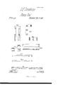
- Figure 2 a plan view, partly in section.
- the rails a a' upon which ⁇ ithe machine used'for cutting the coal runs, are carried at one vend of sleepers or bearers b b of wrought iron.v These sleepers or bearers are made of considerably greater length than the Vdistance between the rails, and the ends ofthe sleepers or bearers to which the railsarev attached,
- This'foot is of cast ronfand on its'un'der side it is formed. with two descending flanges, d d, which are to embrace. wooden sleepers, upon which these ⁇ feet are placed.
- two recesses e areformed, which are te' receive the loweren'ds of the two plates vc c.
- the head of the post is shownl inside view section, under side view-and plan at gs. 5'. This head'its on. the top of the two plates -c c, and'is hushed atff. In this bush a screw-thread is cut, in which the screw g works.
- the link can by'means o f this bolt and nut be connected at any desired height to the'pos't,vby reason of the bolt being able to'slip up or down in ⁇ the slots c2, and-when the link is brought 'to the desired height it can be retained there by screwing up the ⁇ nut on the bolt.
- the two kinds ofl raii'ls'I- employ are shbwn separately at Figures 9 and 10. .
- the rail shown at 'gs. 10 is'a plain rail, and is to support the-wheels ⁇ on thesi'de of the machine nearest to the work. Both these rails are made 'o a length equal to the distance ⁇ that it is desired to have between the sleepers or bearers.
- the sleepers or bearers have notches or recesses formed in them, into which the ends of the rails are dropped. l v v
- the rails shown at gs.9 have at cach end a piece projecting downward, through each of which a hole is formed, as is shown.
- Corresponding holes are also formed through the plates of which the sleeper or bearer-is oomposed, in order that a -bolt maybe passed through these holes to secure the rails in their places,'andA the bolts are by preference secured by a key passingthrough a slot in thebolt, as is shown at o o, fig. 2.
- the rails shown fat'gs. 10 in addition to dropping into notches in the sleepers or bearers, have also notches formed on their undersides, whichnotches embrace the plates of .which the sleepers are composed, and so hold the ends of the sleepers in their places, and as these rails are merely dropped into their places on the sleepers, they may readily bra-removed, -and again' replacedwhen desired.
- a row of wooden sleepers such as are shown in plan view andsection at Figures 8, are first laid along the floor ot' vthe mine, p'arallel with the face of the coal which is being Worked. Upon these are placed the"cast-iron feet of the posts, the posts are then inserted in their places in these feet,and the heads of the' posts are put on, and thescreivs carried by them turned, so as to cause the head of the screw tobear against'the root ⁇ ofthe mine', an'd so wedge the posts firmly in their places.
- a fresh row of pillars is vthen erected, het ⁇ veen the-row ot pillars already set up and the-face of coal that is,being ⁇ vorked,.these pillars being adjusted so that the pins k, which pass through the links carried by them, may also be passed through the holes 1.
- the bolt which connects each link with its post is free to rise and fall in the slots in the post. I When the pins have* been inserted in their places, links are secured to the posts bythe screw-bolts.
- the set of posts first erected may then be removed, and yetlthe bearers will still be retained at the same level at which theywere first laid ⁇ .- 'The level or line at wlchthe rails are laid should in most cases coincide with the line in whichthe seam of coal runs. -If the seam of coalisat any time found to incline upwards or downwards, the level at which the bearers are retained can fat any time -be readily readjvusted.
Landscapes
- Engineering & Computer Science (AREA)
- Mining & Mineral Resources (AREA)
- Mechanical Engineering (AREA)
- Structural Engineering (AREA)
- Life Sciences & Earth Sciences (AREA)
- General Life Sciences & Earth Sciences (AREA)
- Geochemistry & Mineralogy (AREA)
- Geology (AREA)
- Machines For Laying And Maintaining Railways (AREA)
Description
@latten gisten atrnt @fitr-r,
Letters Patent No. 76,418, dated April 7, 1868;*yaatentecl in England, M'areh 8, 1866,
' IMPROVED GOAL-IIIINING MACHINE.
tite tlgehnl'e nient te tu tigen trttcts haten mit mating peut tt tige tame.'
. -1 l l To A LL To wHoM Ir MAY oosoEEN;
' lBe it known that I, Geenen lllnsinnn Doms'rnonrn, of Leeds, in the county oi' York, England, a subject of the Queen of Great Britain, have invented or discovered new and useful Improvements in Fixing or Securing the Rail or Tramways Used when Getting Goal and other Minerals by Machinery; and I,'the said GEQRGE EDMUND DONISTHOEPE, do hereby declare the nature lof the said invention, and in what manner the-same is to be performed, to bepart'icularly described and ascertained in and bythe following statement thereof; that is to say Heretoi'ore, when getting coal and other minerals by means of picks or `cutters actuated by machinery, the
cutters have been u sua-llycarried bytrucks running on rails laid on the loor of the mine, along the` front of theface of coal o'r other mineral upon which the 4cutters are to be made to operate, 'and difficulty has been experienced in laying the rails securely toprevent their shift-ing when' the machine is at work. Now, according to my invention, I employ posts o1' pillars, wedged or-held between the floor and roof of the mide, tp hold the rails` irl-position, Zand prevent them shifting sidewaysaway from the -facc of the'w'ork. The drawings 'hereunto annexed show' the manner in which I prefer to accomplish this object- Figure 1 ofthe drawings being a side view of the arrangement, and
Figure 2 a plan view, partly in section. t
In this arrangement the rails a a', upon which `ithe machine used'for cutting the coal runs, are carried at one vend of sleepers or bearers b b of wrought iron.v These sleepers or bearers are made of considerably greater length than the Vdistance between the rails, and the ends ofthe sleepers or bearers to which the railsarev attached,
are merely supported-'and brought to thedesired heightfrom the door by blocks of wood, as is shown. The
opposite ends ofthe sleepers orbeaners are supportedbya-,ndiixed to posts or pillars wedged or held between the door and the'roof ofthe mineh 4 l The parts of which these posts or pillars are composed are shown separately at Figures 3, 4, 5, and 6. 'At figs. 3, aside view and endview of the main portion or body ofthe postare shown. This part ofthe post is composed o'f two plates, cc, of Vwrought iron, connected together, and held at a distance apart from each other by rivets andvdistance-pieces l el, as is shown. The foot of the post is shown separately in plan, underside view, and section, at iig. 4. This'foot is of cast ronfand on its'un'der side it is formed. with two descending flanges, d d, which are to embrace. wooden sleepers, upon which these` feet are placed. In the upper surface .of 'the foot two recesses e areformed, which are te' receive the loweren'ds of the two plates vc c. The head of the post is shownl inside view section, under side view-and plan at gs. 5'. This head'its on. the top of the two plates -c c, and'is hushed atff. In this bush a screw-thread is cut, in which the screw g works. On-the top of this'screw is a circular head, which is to bear against the roof or ceiling of the' mine, Vabloclr of wood being b`y preference placed between them, as is shown` at h h, lg. l. The. sleepers or bearers which support the rails are composed of two' parallel plates of wrought-(iron, connected'together, at a distanceapart from each other, by rivetsl and distance-pieces,'as is shown in4 the plan view of one 'of the sleepersfat Figure 7..
Through the plates of which the sleeper is composed, circularholes,1 2 3 5, are formed, at distances apart fromv each other, as is shown,the distance'betwcen the holes corresponding to the depth of cut which is madv into the coalhy`the'cutters. These holes lare-to allow-of n pin, lc, beingfpassedthrough, which pin also passes through a hole, Z,-in alink', m, shown separately in side ricw, edge view, and section atgs. 6. y".lhislinl; is placed between the plates c c of the post, and is lconnected. to them by a bolt andnut, n, which passes throughslots cZ in these plates, and also through the hole inthe .upper part ofthe linlt. The link can by'means o f this bolt and nut be connected at any desired height to the'pos't,vby reason of the bolt being able to'slip up or down in` the slots c2, and-when the link is brought 'to the desired height it can be retained there by screwing up the `nut on the bolt. The two kinds ofl raii'ls'I- employ are shbwn separately at Figures 9 and 10. .The rail shown at figs. 9, supports the rollers or wheels lat the s ide of the machine farthest from the work,-and rhas a screw-rack formed on its upper face, into which a worm or screw on'the machine gears, and by which the machine is caused to travelforward when at work. 1 l
The rail shown at 'gs. 10 is'a plain rail, and is to support the-wheels `on thesi'de of the machine nearest to the work. Both these rails are made 'o a length equal to the distance `that it is desired to have between the sleepers or bearers. The sleepers or bearers have notches or recesses formed in them, into which the ends of the rails are dropped. l v v The rails shown at gs.9 have at cach end a piece projecting downward, through each of which a hole is formed, as is shown. Corresponding holes are also formed through the plates of which the sleeper or bearer-is oomposed, in order that a -bolt maybe passed through these holes to secure the rails in their places,'andA the bolts are by preference secured by a key passingthrough a slot in thebolt, as is shown at o o, fig. 2.
The rails shown fat'gs. 10, in addition to dropping into notches in the sleepers or bearers, have also notches formed on their undersides, whichnotches embrace the plates of .which the sleepers are composed, and so hold the ends of the sleepers in their places, and as these rails are merely dropped into their places on the sleepers, they may readily bra-removed, -and again' replacedwhen desired. I
Inorder to set up a. line of rails supported in themanner above described, a row of wooden sleepers, such as are shown in plan view andsection at Figures 8, are first laid along the floor ot' vthe mine, p'arallel with the face of the coal which is being Worked. Upon these are placed the"cast-iron feet of the posts, the posts are then inserted in their places in these feet,and the heads of the' posts are put on, and thescreivs carried by them turned, so as to cause the head of the screw tobear against'the root` ofthe mine', an'd so wedge the posts firmly in their places. 'Ihe sleepers or bearers which support the rails are then passed into their places through the posts, and a pin, 7c, is passed through the link carried by cach post, and also through the holes 1 formed in the sleeper or bearer. The ends of the bearers which are nearest to the face of coal to b e Worked, and which support the rails, are then wedged up to the desired level, and the ends which are connected to the pillars are also brought to the proper level, and secured there by means of the bolt and nut nl The rails are afterwards secured to the sleepers or bearers. When the cuttinglmachine has travelled along railsl so laid in position, and has made the requisite numberof cuts in -the face o t' the Work, the coal is broken oil` by means of levers or wedges, and'i's removedfthe bearers are then moved a distance forward towards the work, in order that the pins It may be passed through the holes in the bearers; the ends of the'bearers nearest the face of'the work are then again wedged up, and the machineis `caused to work a fresh series of cuts in the coal; the coal is then again removed, and afterwards the sleepers o r hearersare again moved'forwards, and soon until the pinl has been placed in the last hole, 5, in the bearer. A fresh row of pillars is vthen erected, het\veen the-row ot pillars already set up and the-face of coal that is,being \vorked,.these pillars being adjusted so that the pins k, which pass through the links carried by them, may also be passed through the holes 1. Before the pins are-passed through these holes, the bolt which connects each link with its post is free to rise and fall in the slots in the post. I When the pins have* been inserted in their places, links are secured to the posts bythe screw-bolts. The set of posts first erected may then be removed, and yetlthe bearers will still be retained at the same level at which theywere first laid`.- 'The level or line at wlchthe rails are laid should in most cases coincide with the line in whichthe seam of coal runs. -If the seam of coalisat any time found to incline upwards or downwards, the level at which the bearers are retained can fat any time -be readily readjvusted.
Having thus described the nature of my invention, and the vmanner of performing the same, I would haveit understood thatalthoughI have only given a. precise description of one arrangement of apparatus for carrying out my invention, yet I do notconne. myself .to this arrangement, as other arrangements of apparatus may be employed in carrying out my invention. I y
What I claim, is- .A i The holding in position the rails (upon which machines used in getting coal and other minerals run), by posts or pillars wedgedY or held between the floor and roof of the mine, substantially as herein described.
' f I G. JE. DONISTHORPE.
Witnesses:
'W' IH' GOWLEY }Both of Leeds, England.v
Tues. GRISDALE, Jr.
Publications (1)
| Publication Number | Publication Date |
|---|---|
| US76418A true US76418A (en) | 1868-04-07 |
Family
ID=2145921
Family Applications (1)
| Application Number | Title | Priority Date | Filing Date |
|---|---|---|---|
| US76418D Expired - Lifetime US76418A (en) | Peters |
Country Status (1)
| Country | Link |
|---|---|
| US (1) | US76418A (en) |
Cited By (1)
| Publication number | Priority date | Publication date | Assignee | Title |
|---|---|---|---|---|
| US20220127804A1 (en) * | 2020-10-27 | 2022-04-28 | Southwest Jiaotong University | Two-stage energy dissipation type shed tunnel support structure connected by principle of dougong and a design method thereof |
-
0
- US US76418D patent/US76418A/en not_active Expired - Lifetime
Cited By (2)
| Publication number | Priority date | Publication date | Assignee | Title |
|---|---|---|---|---|
| US20220127804A1 (en) * | 2020-10-27 | 2022-04-28 | Southwest Jiaotong University | Two-stage energy dissipation type shed tunnel support structure connected by principle of dougong and a design method thereof |
| US11535990B2 (en) * | 2020-10-27 | 2022-12-27 | Southwest Jiaotong University | Two-stage energy dissipation type shed tunnel support structure connected by principle of Dougong and a design method thereof |
Similar Documents
| Publication | Publication Date | Title |
|---|---|---|
| US76418A (en) | Peters | |
| US8149A (en) | Railing | |
| US510198A (en) | Island | |
| US1185549A (en) | Rail-joint. | |
| US1126501A (en) | Rail-chair. | |
| US109141A (en) | Ittm s | |
| US635909A (en) | Mining-machine. | |
| US527805A (en) | George norwood | |
| US598764A (en) | Combination railroad-tie | |
| US1675178A (en) | Tie-plate | |
| US1594A (en) | William kits sell | |
| US435408A (en) | Switch-rail and blank therefor | |
| US319024A (en) | Railway-frog | |
| US71905A (en) | Staats n | |
| US73003A (en) | Improvement in elevated railroads | |
| US323940A (en) | Mining-machine | |
| US65540A (en) | Improved railway ghaie | |
| US469947A (en) | Rail-fastening device | |
| US380923A (en) | Railway-frog | |
| US1004886A (en) | Metallic tie and rail-fastener. | |
| US70731A (en) | Improvement in eaileoad teaok | |
| US3712A (en) | Key for fastening the bails of railroads to their chaies | |
| US862086A (en) | Metallic tie and rail-fastener. | |
| US1782941A (en) | Device for shunting vehicles off a main line of track | |
| US527682A (en) | Steel combination railroad-tie |