US7637348B2 - Electric power steering apparatus equipped with tension adjusting mechanism - Google Patents
Electric power steering apparatus equipped with tension adjusting mechanism Download PDFInfo
- Publication number
- US7637348B2 US7637348B2 US11/880,238 US88023807A US7637348B2 US 7637348 B2 US7637348 B2 US 7637348B2 US 88023807 A US88023807 A US 88023807A US 7637348 B2 US7637348 B2 US 7637348B2
- Authority
- US
- United States
- Prior art keywords
- electric power
- motor
- steering apparatus
- power steering
- motor housing
- Prior art date
- Legal status (The legal status is an assumption and is not a legal conclusion. Google has not performed a legal analysis and makes no representation as to the accuracy of the status listed.)
- Active, expires
Links
Images


Classifications
-
- B—PERFORMING OPERATIONS; TRANSPORTING
- B62—LAND VEHICLES FOR TRAVELLING OTHERWISE THAN ON RAILS
- B62D—MOTOR VEHICLES; TRAILERS
- B62D5/00—Power-assisted or power-driven steering
- B62D5/04—Power-assisted or power-driven steering electrical, e.g. using an electric servo-motor connected to, or forming part of, the steering gear
- B62D5/0421—Electric motor acting on or near steering gear
- B62D5/0424—Electric motor acting on or near steering gear the axes of motor and final driven element of steering gear, e.g. rack, being parallel
-
- F—MECHANICAL ENGINEERING; LIGHTING; HEATING; WEAPONS; BLASTING
- F16—ENGINEERING ELEMENTS AND UNITS; GENERAL MEASURES FOR PRODUCING AND MAINTAINING EFFECTIVE FUNCTIONING OF MACHINES OR INSTALLATIONS; THERMAL INSULATION IN GENERAL
- F16H—GEARING
- F16H25/00—Gearings comprising primarily only cams, cam-followers and screw-and-nut mechanisms
- F16H25/18—Gearings comprising primarily only cams, cam-followers and screw-and-nut mechanisms for conveying or interconverting oscillating or reciprocating motions
- F16H25/20—Screw mechanisms
- F16H2025/2062—Arrangements for driving the actuator
- F16H2025/2096—Arrangements for driving the actuator using endless flexible members
-
- F—MECHANICAL ENGINEERING; LIGHTING; HEATING; WEAPONS; BLASTING
- F16—ENGINEERING ELEMENTS AND UNITS; GENERAL MEASURES FOR PRODUCING AND MAINTAINING EFFECTIVE FUNCTIONING OF MACHINES OR INSTALLATIONS; THERMAL INSULATION IN GENERAL
- F16H—GEARING
- F16H7/00—Gearings for conveying rotary motion by endless flexible members
- F16H7/08—Means for varying tension of belts, ropes or chains
- F16H7/10—Means for varying tension of belts, ropes or chains by adjusting the axis of a pulley
- F16H7/14—Means for varying tension of belts, ropes or chains by adjusting the axis of a pulley of a driving or driven pulley
Definitions
- the present invention relates to an electric power steering apparatus, and more particularly to an electric power steering apparatus equipped with a tension adjusting mechanism which can adjust a rotation angle of a motor housing capable of relatively rotating respective to a gear housing, so as to adjust tension of a belt.
- hydraulic power steering apparatuses have been used as power steering apparatuses for vehicles. Since the 1990's, electric power steering apparatuses using a motor have been popularized.
- a hydraulic pump which is a power source providing assistant steering power
- an engine which is a power source providing assistant steering power
- an electric power steering apparatus if torque is generated by rotation of a steering wheel, a motor provides assistant steering power proportionate to the generated steering torque. Therefore, when the electric power steering apparatus is used, it is possible to improve energy efficiency in comparison with the hydraulic power steering apparatus.
- FIG. 1 is a block diagram of an electric power steering apparatus according to the conventional art.
- an electric power steering apparatus includes a steering system 100 extending from a steering wheel 101 to each wheel 108 on both sides of the vehicle, and an assistant power mechanism 120 providing assistant steering power to the steering system.
- the steering system 100 has an upper part connected to the steering wheel 101 to rotate along the steering wheel 101 , and a lower part connected to a pinion shaft 104 by a pair of universal joints 103 . Further, the pinion shaft 104 is connected to a rack bar 109 through a rack-pinion mechanism 105 , while both ends of the rack bar 109 are connected to both wheels 108 of the vehicle by tie rods 106 and knuckle arms 107 , respectively.
- the rack-pinion mechanism 105 includes a pinion gear 111 formed on a lower part of the pinion shaft 104 , and a rack gear 112 formed on a peripheral surface of one end of the rack bar 109 and engaged with the pinion gear 111 .
- the rotational movement of the pinion shaft 104 is changed to a linear movement of the rack bar 109 through the rack-pinion mechanism 105 .
- the pinion shaft 104 rotates, the rack bar 109 straightly moves along the axial direction thereof depending on the rotation of the pinion shaft 104 , and the linear movement of the rack bar 109 causes the tie rods 106 and knuckle arms 107 to steer the wheels 108 .
- the assistant power mechanism 120 includes a torque sensor 121 for sensing steering torque applied to the steering wheel 101 by the driver and outputting an electric signal in proportion to the sensed steering torque and an electronic control unit 123 for generating a control signal depending on the electric signal transmitted from the torque sensor 121 .
- the assistant power mechanism 120 also includes a motor 130 for generating assistant steering power according to the control signal transmitted from the electronic control unit 123 , and a belt-type power transmission apparatus 140 for transferring the assistant power generated by the motor 130 to the rack bar 109 through the belt.
- the steering torque generated by the rotation of the steering wheel 101 is transferred through the rack-pinion mechanism 105 to the rack bar 109 .
- the assistant steering power which the motor 130 generates depending on the generated steering torque, is transferred by the belt-type power transmission apparatus to the rack bar 109 .
- the torque generated in the steering system 100 and the assistant steering power generated by the motor 130 are combined with each other so as to cause the rack bar to be moved along an axis thereof.
- the electric power steering apparatus may have a structure that the assistant steering power generated in the motor 130 is transferred to the steering wheel 102 or the pinion shaft 104 .
- FIG. 2 is a sectional view illustrating the conventional electric power steering apparatus.
- the conventional electric power steering apparatus for the vehicle includes the rack bar 109 extending in a transverse direction of the vehicle and having the rack gear in an outer peripheral surface of an end thereof, the pinion shaft 104 having the pinion gear engaged with the rack gear.
- the conventional electric power steering apparatus includes a ball screw part 210 having a ball nut 205 engaged with a ball screw 203 through balls 201 , the belt-type power transmission apparatus 140 connecting a ball nut 205 to the shaft 221 of the motor, and the motor 130 .
- the pinion shaft 104 is connected to the steering wheel through the steering shaft, and the rack bar 109 having the screw formed by a predetermined length at one end thereof is contained in a rack housing. Furthermore, the rack housing includes the first housing 225 having the rack gear and the second housing 227 having the motor.
- the belt-type electric transmission apparatus 140 includes a belt connecting the shaft 221 of the motor 221 and the ball nut 205 , and transfers steering assistance power generated in the motor 130 in proportion to the steering toque applied to the steering wheel to the rack bar 109 through the ball nut 205 .
- the belt-type electric transmission apparatus 140 enables vibration and impact, etc. of the rack bar 109 not to be directly transferred to the motor 130 .
- vibration is generated in the belt and can be transferred to the body of the vehicle, thereby causing noise.
- the present invention has been made to solve the above-mentioned problems occurring in the prior art, and the present invention provides an electric power steering apparatus equipped with a tension adjusting mechanism which can adjust the rotation angle of a motor housing capable of relatively rotating respective to a gear housing so as to adjust the tension of a belt.
- an electric power steering apparatus including: a motor for providing a assistant steering power; a following pulley connected with the motor through a belt to receive a driving force; a gear housing surrounding the following pulley; a motor housing rotatably assembled with the gear housing; and a tension adjusting mechanism for adjusting a rotation angle of the motor housing so as to adjust a tension of the belt.
- FIG. 1 is a block diagram of the conventional electric power steering apparatus
- FIG. 2 is a sectional view of a part of the conventional electric power steering apparatus
- FIG. 3 a is a perspective view illustrating a part of an electric power steering apparatus according to the first embodiment of the present invention
- FIG. 3 b is a sectional view of the electric power steering apparatus in the direction A-A of FIG. 3 a ;
- FIG. 4 is a cross-sectional view of an electric power steering apparatus according to the second embodiment of the present invention.
- the electric power steering apparatus includes a motor 130 for providing steering assistance power, a driving pulley 301 extending from one end of the motor 130 , and a following pulley 305 connected to the driving pulley 301 of the motor 130 through a belt 303 so as to receive driving force.
- the electric power steering apparatus also includes a gear housing 307 surrounding the driving pulley 301 and the following pulley 305 , a motor housing 309 rotatably assembled with the gear housing 307 , and a tension adjusting mechanism 311 for adjusting the rotation angel of the motor housing 309 so as to adjust the tension of the belt 310 .
- the driving pulley 301 is connected with a rotor (not shown) of the motor so as to be rotated, and the following pulley 305 is connected with the driving pulley 301 through the belt 303 so as to receive the rotational force of the motor 130 . Furthermore, the following pulley 305 makes contact with the rack bar 109 through a ball screw (not shown).
- the gear housing 307 surrounds the driving pulley 301 and the following pulley 305 .
- a coupling part 313 extends from left and right sides of an upper part of the gear housing 307 , and the coupling part 313 has guide holes 315 of a circular shape.
- the gear housing 307 and the motor housing 309 are assembled with each other through bolts 317 extending through corresponding guide hole 315 to be inserted into the motor housing 309 .
- a rotor (not shown) protruding from the motor 130 extends through the motor housing 309 and is then assembled with the driving pulley 301 .
- the motor housing 309 is rotatably assembled with the gear housing 307 through the guide holes 315 and the bolts 317 .
- the motor housing 309 rotates along the guide holes 315 having a circular shape so that the center of an imaginary circle formed by imaginary extension lines of the guide holes 315 serves as the center 319 of rotation of the motor housing 309 .
- the driving pulley 310 extends through a point spaced a predetermined distance from the center 319 of the rotation of the motor housing 309 .
- the motor housing 309 is relatively rotated respective to the gear housing 307 so that the axial center 321 of the driving pulley 301 revolves about the center 319 of rotation of the motor housing 309 .
- the tension adjusting mechanism 311 is an apparatus for adjusting a relative rotation angle of the motor housing 309 respective to the gear housing 307 so as to adjust the tension of the belt 303 .
- the tension adjusting mechanism 311 includes a supporting member 323 and an adjusting bolt 325 .
- the supporting member 323 is assembled with the coupling part 313 of the gear housing 307 .
- the adjusting bolt 325 is inserted into an end of the supporting member 323 so that an end of the adjusting member 325 makes contact with a side surface of the motor housing 309 .
- the supporting member 323 is fastened to the coupling part 313 by a coupling means such as bolt, etc., or may be configured as an integrated part of the coupling part 313 .
- the adjusting bolt 325 is rotated so as to apply a predetermined amount of power to the motor housing 309 .
- the motor housing 309 is pushed by an end of the adjusting bolt 325 so that the motor housing 309 is relatively rotated respective to the gear housing 307 .
- the relative rotation angle can be easily adjusted. Accordingly, the tension of the belt 303 can be easily adjusted.
- the distance between the driving pulley 301 and the following pulley 305 is closer so that the tension of the belt 303 is lessened.
- the adjusting bolt 325 fixes the location of the motor housing 309 . Therefore, it is possible to prevent release of the bolt 317 , which may cause loss of the tension of the belt 303 , resulting in loss of the steering function.
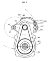
- FIG. 4 is a cross-sectional view of an electric power steering apparatus according to the second embodiment of the present invention.
- the coupling part 313 is formed in a right side of an upper part of the gear housing 307 and a hinge part 401 is formed in a left side thereof. Furthermore, a hinge shaft 403 extends through the hinge part 401 to be inserted into the motor housing 309 so that center 319 of rotation of the motor housing 309 can be equal to an axial center of the hinge shaft 403 . Meanwhile, the center 319 of rotation of the motor housing 309 is equal to the center of the imaginary circle formed by imaginary extension lines of the guide holes 315 or the axial center of the hinge shaft 403 .
- the supporting member 323 is formed in the upper part of the coupling part 313 , and the adjusting bolt 325 extends through the supporting member 313 so that an end of the adjusting bolt 325 makes contact with an outer peripheral surface of the motor housing 309 .
- the adjusting bolt 325 is adjusted so that the motor housing 309 can be rotated about the hinge shaft 403 respective to the gear housing 307 . Accordingly, the strength of tension of the belt 303 can be controlled.
Landscapes
- Engineering & Computer Science (AREA)
- Chemical & Material Sciences (AREA)
- Combustion & Propulsion (AREA)
- Transportation (AREA)
- Mechanical Engineering (AREA)
- Power Steering Mechanism (AREA)
- Devices For Conveying Motion By Means Of Endless Flexible Members (AREA)
Abstract
Description
Claims (7)
Applications Claiming Priority (2)
| Application Number | Priority Date | Filing Date | Title |
|---|---|---|---|
| KR2006-75361 | 2006-08-10 | ||
| KR20060075631 | 2006-08-10 |
Publications (2)
| Publication Number | Publication Date |
|---|---|
| US20080035415A1 US20080035415A1 (en) | 2008-02-14 |
| US7637348B2 true US7637348B2 (en) | 2009-12-29 |
Family
ID=38445672
Family Applications (1)
| Application Number | Title | Priority Date | Filing Date |
|---|---|---|---|
| US11/880,238 Active 2027-11-21 US7637348B2 (en) | 2006-08-10 | 2007-07-20 | Electric power steering apparatus equipped with tension adjusting mechanism |
Country Status (4)
| Country | Link |
|---|---|
| US (1) | US7637348B2 (en) |
| EP (1) | EP1886899A1 (en) |
| JP (1) | JP2008044604A (en) |
| CN (1) | CN101121415A (en) |
Cited By (6)
| Publication number | Priority date | Publication date | Assignee | Title |
|---|---|---|---|---|
| US20090250286A1 (en) * | 2006-04-07 | 2009-10-08 | Wilfried Leutner | Worm-belt transmission of a power-steering drive |
| US20130043088A1 (en) * | 2011-08-16 | 2013-02-21 | Nam Hwan HEO | Electric power steering apparatus |
| US20140302954A1 (en) * | 2011-12-26 | 2014-10-09 | Toyota Jidosha Kabushiki Kaisha | Electrical power steering apparatus |
| US9409593B2 (en) * | 2015-01-12 | 2016-08-09 | Mando Corporation | Rack type electric power steering apparatus |
| US20200088275A1 (en) * | 2017-05-25 | 2020-03-19 | Zhejiang Dahua Technology Co., Ltd. | Belt driven system and tensioner thereof |
| US20210380160A1 (en) * | 2018-12-21 | 2021-12-09 | Thyssenkrupp Presta Ag | Power assistance drive for a steering column, and steering column for a motor vehicle |
Families Citing this family (14)
| Publication number | Priority date | Publication date | Assignee | Title |
|---|---|---|---|---|
| DE102005015451A1 (en) * | 2005-04-04 | 2006-10-05 | Thyssenkrupp Presta Ag | Steering system e.g. servo-steering mechanism, has motor, which along with sub housing is adjusted at its rotational axis in radial direction, and worm shaft is supported at its ends in bearing and differential coupling |
| DE102007004521A1 (en) * | 2007-01-24 | 2008-07-31 | Thyssenkrupp Presta Steertec Gmbh | Electric power steering with belt drive |
| DE102007004520A1 (en) * | 2007-01-24 | 2008-07-31 | Thyssenkrupp Presta Steertec Gmbh | Electric power steering with belt drive and non-contact belt tension |
| JP2012025246A (en) * | 2010-07-22 | 2012-02-09 | Jtekt Corp | Electric power steering apparatus and assembly method thereof |
| WO2012173096A1 (en) * | 2011-06-16 | 2012-12-20 | 日本精工株式会社 | Electric power steering apparatus |
| CN104918839A (en) * | 2013-01-24 | 2015-09-16 | 丰田自动车株式会社 | Electric Power Steering |
| CN103601026B (en) * | 2013-11-19 | 2016-01-06 | 桂林电器科学研究院有限公司 | The jockey pulley control apparatus of film stretching manufacturing line traction machine |
| JP6421607B2 (en) * | 2015-01-15 | 2018-11-14 | 株式会社ジェイテクト | Steering device |
| KR102216192B1 (en) * | 2015-06-19 | 2021-02-16 | 현대모비스 주식회사 | Power steering apparatus |
| CN107725711B (en) * | 2017-09-01 | 2020-10-30 | 广东星光传动股份有限公司 | Belt gear speed reducer |
| US10488282B2 (en) * | 2017-11-08 | 2019-11-26 | Rockwell Automation Technologies, Inc. | System and method for monitoring installation and health of belt driven motor/drive applications |
| CN109210160B (en) * | 2018-11-06 | 2019-09-20 | 清华大学 | Train tensioning apparatus and train |
| CN113775716A (en) * | 2021-09-17 | 2021-12-10 | 中国第一汽车股份有限公司 | Belt tensioning adjustment mechanism and electric power steering gear |
| DE102021212522A1 (en) * | 2021-11-08 | 2023-05-11 | Thyssenkrupp Ag | Adjusting drive for a motor-adjustable steering column and steering column for a motor vehicle |
Citations (22)
| Publication number | Priority date | Publication date | Assignee | Title |
|---|---|---|---|---|
| US5465210A (en) | 1994-08-18 | 1995-11-07 | General Motors Corporation | Method for determining a vehicle steering wheel center position |
| EP0982564A1 (en) | 1998-03-17 | 2000-03-01 | Matsushita Electric Industrial Co., Ltd. | Rotation angle detector |
| DE10103404A1 (en) | 2001-01-26 | 2002-08-01 | Daimler Chrysler Ag | Vehicle steering system, has controller for processing signals from steering position sensor with stored relationship between positions of electric motor and of steering device |
| EP1283148A2 (en) | 2001-08-10 | 2003-02-12 | Delphi Technologies, Inc. | Robust determination of handwheel position |
| EP1318061A2 (en) | 2001-12-04 | 2003-06-11 | Toyoda Machine Works, LTD. | Position detector correction method and electrically-powered steering apparatus |
| US20030107200A1 (en) * | 2001-12-10 | 2003-06-12 | Trw Inc. | Rack housing for steering gear |
| US20040043854A1 (en) * | 2002-08-30 | 2004-03-04 | Fraley Richard R. | Belt tensioner for electric power steering unit |
| DE102004028855A1 (en) | 2003-06-16 | 2005-01-13 | Matsushita Electric Industrial Co., Ltd., Kadoma | Steering rotation-angle detector for motor vehicle, has controller to detect rotation angle of rotary element connected to steering, based on output of detectors detecting rotation of detecting-objects co-operating with rotary element |
| EP1503172A2 (en) | 2003-07-31 | 2005-02-02 | Alps Electric Co., Ltd. | Rotation detecting device and automobile with the same |
| US20050079939A1 (en) | 2003-10-09 | 2005-04-14 | Simmons Stanley R. | Belt tensioner and method |
| US20050121251A1 (en) * | 2003-05-06 | 2005-06-09 | Nsk Ltd. | Belt speed reducing apparatus for electric power steering apparatus and electric power steering apparatus |
| US20050133297A1 (en) * | 2002-08-22 | 2005-06-23 | Nsk Ltd. | Electric power steering apparatus |
| DE102004012377A1 (en) | 2004-03-13 | 2005-09-29 | Valeo Schalter Und Sensoren Gmbh | Sensor assembly, to establish rotary angle settings of vehicle steering column, has rotor with two sets of coding to be scanned optically to give total and incremental output signals for evaluation |
| US20050247514A1 (en) | 2003-01-16 | 2005-11-10 | Trw Automotive Gmbh | Belt tightener for a steering booster |
| JP2005349862A (en) | 2004-06-08 | 2005-12-22 | Showa Corp | Power steering device |
| JP2006027577A (en) | 2004-07-22 | 2006-02-02 | Kayaba Ind Co Ltd | Electric power steering device |
| US20060076181A1 (en) * | 2003-02-03 | 2006-04-13 | Tetsuya Murakami | Electric power-steering device |
| US20060156839A1 (en) * | 2003-01-10 | 2006-07-20 | Seiji Ueno | Speed reduction gear of electric power steering device |
| US20060183583A1 (en) * | 2005-02-16 | 2006-08-17 | Showa Corporation | Motor-driven steering apparatus |
| US20070095600A1 (en) * | 2005-10-19 | 2007-05-03 | Mando Corporation | Belt-type transmission and electric power steering apparatus having the same |
| EP1792804A1 (en) | 2005-12-01 | 2007-06-06 | Mando Corporation | Motor-driven power steering system for a vehicle with a device for adjusting the tension of a transmission belt |
| US7360624B2 (en) * | 2002-01-29 | 2008-04-22 | Jtekt Corporation | Electric power steering apparatus |
Family Cites Families (3)
| Publication number | Priority date | Publication date | Assignee | Title |
|---|---|---|---|---|
| KR20050038625A (en) * | 2002-08-22 | 2005-04-27 | 닛뽄 세이꼬 가부시기가이샤 | Electric power steering device |
| JP3976031B2 (en) * | 2003-05-06 | 2007-09-12 | 日本精工株式会社 | Belt reduction device for electric power steering device and electric power steering device |
| JP2005022634A (en) * | 2003-06-10 | 2005-01-27 | Showa Corp | Electric power steering device |
-
2007
- 2007-07-12 EP EP07013660A patent/EP1886899A1/en not_active Withdrawn
- 2007-07-19 JP JP2007188593A patent/JP2008044604A/en active Pending
- 2007-07-20 US US11/880,238 patent/US7637348B2/en active Active
- 2007-08-09 CN CNA2007101407091A patent/CN101121415A/en active Pending
Patent Citations (23)
| Publication number | Priority date | Publication date | Assignee | Title |
|---|---|---|---|---|
| US5465210A (en) | 1994-08-18 | 1995-11-07 | General Motors Corporation | Method for determining a vehicle steering wheel center position |
| EP0982564A1 (en) | 1998-03-17 | 2000-03-01 | Matsushita Electric Industrial Co., Ltd. | Rotation angle detector |
| DE10103404A1 (en) | 2001-01-26 | 2002-08-01 | Daimler Chrysler Ag | Vehicle steering system, has controller for processing signals from steering position sensor with stored relationship between positions of electric motor and of steering device |
| EP1283148A2 (en) | 2001-08-10 | 2003-02-12 | Delphi Technologies, Inc. | Robust determination of handwheel position |
| EP1318061A2 (en) | 2001-12-04 | 2003-06-11 | Toyoda Machine Works, LTD. | Position detector correction method and electrically-powered steering apparatus |
| US20030107200A1 (en) * | 2001-12-10 | 2003-06-12 | Trw Inc. | Rack housing for steering gear |
| US7490696B2 (en) * | 2002-01-29 | 2009-02-17 | Jtekt Corporation | Electric power steering apparatus |
| US7360624B2 (en) * | 2002-01-29 | 2008-04-22 | Jtekt Corporation | Electric power steering apparatus |
| US20050133297A1 (en) * | 2002-08-22 | 2005-06-23 | Nsk Ltd. | Electric power steering apparatus |
| US20040043854A1 (en) * | 2002-08-30 | 2004-03-04 | Fraley Richard R. | Belt tensioner for electric power steering unit |
| US20060156839A1 (en) * | 2003-01-10 | 2006-07-20 | Seiji Ueno | Speed reduction gear of electric power steering device |
| US20050247514A1 (en) | 2003-01-16 | 2005-11-10 | Trw Automotive Gmbh | Belt tightener for a steering booster |
| US20060076181A1 (en) * | 2003-02-03 | 2006-04-13 | Tetsuya Murakami | Electric power-steering device |
| US20050121251A1 (en) * | 2003-05-06 | 2005-06-09 | Nsk Ltd. | Belt speed reducing apparatus for electric power steering apparatus and electric power steering apparatus |
| DE102004028855A1 (en) | 2003-06-16 | 2005-01-13 | Matsushita Electric Industrial Co., Ltd., Kadoma | Steering rotation-angle detector for motor vehicle, has controller to detect rotation angle of rotary element connected to steering, based on output of detectors detecting rotation of detecting-objects co-operating with rotary element |
| EP1503172A2 (en) | 2003-07-31 | 2005-02-02 | Alps Electric Co., Ltd. | Rotation detecting device and automobile with the same |
| US20050079939A1 (en) | 2003-10-09 | 2005-04-14 | Simmons Stanley R. | Belt tensioner and method |
| DE102004012377A1 (en) | 2004-03-13 | 2005-09-29 | Valeo Schalter Und Sensoren Gmbh | Sensor assembly, to establish rotary angle settings of vehicle steering column, has rotor with two sets of coding to be scanned optically to give total and incremental output signals for evaluation |
| JP2005349862A (en) | 2004-06-08 | 2005-12-22 | Showa Corp | Power steering device |
| JP2006027577A (en) | 2004-07-22 | 2006-02-02 | Kayaba Ind Co Ltd | Electric power steering device |
| US20060183583A1 (en) * | 2005-02-16 | 2006-08-17 | Showa Corporation | Motor-driven steering apparatus |
| US20070095600A1 (en) * | 2005-10-19 | 2007-05-03 | Mando Corporation | Belt-type transmission and electric power steering apparatus having the same |
| EP1792804A1 (en) | 2005-12-01 | 2007-06-06 | Mando Corporation | Motor-driven power steering system for a vehicle with a device for adjusting the tension of a transmission belt |
Non-Patent Citations (2)
| Title |
|---|
| European Search Report for Application No. 06025655.9-1523, dated Nov. 7, 2007. |
| European Search Report for Application No. 07013660.1-2425, dated Sep. 28, 2007. |
Cited By (11)
| Publication number | Priority date | Publication date | Assignee | Title |
|---|---|---|---|---|
| US20090250286A1 (en) * | 2006-04-07 | 2009-10-08 | Wilfried Leutner | Worm-belt transmission of a power-steering drive |
| US8360910B2 (en) * | 2006-04-07 | 2013-01-29 | Zf Lenksysteme Gmbh | Worm-belt transmission of a power-steering drive |
| US20130043088A1 (en) * | 2011-08-16 | 2013-02-21 | Nam Hwan HEO | Electric power steering apparatus |
| US8950543B2 (en) * | 2011-08-16 | 2015-02-10 | Mando Corporation | Electric power steering apparatus |
| US20140302954A1 (en) * | 2011-12-26 | 2014-10-09 | Toyota Jidosha Kabushiki Kaisha | Electrical power steering apparatus |
| US9051002B2 (en) * | 2011-12-26 | 2015-06-09 | Toyota Jidosha Kabushiki Kaisha | Electrical power steering apparatus |
| US9409593B2 (en) * | 2015-01-12 | 2016-08-09 | Mando Corporation | Rack type electric power steering apparatus |
| US20200088275A1 (en) * | 2017-05-25 | 2020-03-19 | Zhejiang Dahua Technology Co., Ltd. | Belt driven system and tensioner thereof |
| US11754150B2 (en) * | 2017-05-25 | 2023-09-12 | Zhejiang Dahua Technology Co., Ltd. | Belt driven system and tensioner thereof |
| US20210380160A1 (en) * | 2018-12-21 | 2021-12-09 | Thyssenkrupp Presta Ag | Power assistance drive for a steering column, and steering column for a motor vehicle |
| US12103605B2 (en) * | 2018-12-21 | 2024-10-01 | Thyssenkrupp Presta Ag | Power assistance drive for a steering column, and steering column for a motor vehicle |
Also Published As
| Publication number | Publication date |
|---|---|
| US20080035415A1 (en) | 2008-02-14 |
| EP1886899A1 (en) | 2008-02-13 |
| JP2008044604A (en) | 2008-02-28 |
| CN101121415A (en) | 2008-02-13 |
Similar Documents
| Publication | Publication Date | Title |
|---|---|---|
| US7637348B2 (en) | Electric power steering apparatus equipped with tension adjusting mechanism | |
| US8001866B2 (en) | Electronic power steering apparatus | |
| KR100621347B1 (en) | Electric power assist steering in cars | |
| US20070089926A1 (en) | Electric power steering apparatus for automobile | |
| KR20130019217A (en) | Electric power steering apparatus | |
| JP2000043739A (en) | Electric steering device | |
| KR100646406B1 (en) | Electric power assist steering in motor vehicle with belt transmission | |
| US20230085265A1 (en) | Electric power steering apparatus | |
| US20070175295A1 (en) | Steering apparatus | |
| JP2007153300A (en) | Motor drive type steering device | |
| KR20070042632A (en) | Belt-type transmission and electric power steering of automobile with same | |
| KR101246933B1 (en) | Reducer of Electronic Power Steering Apparatus | |
| KR102408739B1 (en) | Rack Assist Type Electric Power Steering Apparatus | |
| US20070095603A1 (en) | Belt-type electric power steering apparatus | |
| KR101085336B1 (en) | Electric power assist steering of automobile with damping coupler with serration | |
| WO2006043669A1 (en) | Electric power steering device | |
| KR101124840B1 (en) | Reducer of Electronic Power Steering Apparatus and Electronic Power Steering Apparatus having The Same | |
| KR20080022425A (en) | Electric steering with reduced rattle noise | |
| CN116142289A (en) | Steer-by-wire steering | |
| KR20120029152A (en) | Rack assist type electric power steering system | |
| KR20090039109A (en) | Electric power assisted steering with noise reduction member | |
| JPH1148995A (en) | Electric power steering system | |
| JP2005324708A (en) | Electric power steering device | |
| JP2009079677A (en) | Joint structure of yoke and rotating shaft in steering device | |
| KR20110116638A (en) | Reducer of electric power assisted steering and electric power assisted steering with same |
Legal Events
| Date | Code | Title | Description |
|---|---|---|---|
| AS | Assignment |
Owner name: MANDO CORPORATION, KOREA, REPUBLIC OF Free format text: ASSIGNMENT OF ASSIGNORS INTEREST;ASSIGNOR:NAMGUNG, JOO;REEL/FRAME:019632/0760 Effective date: 20070703 |
|
| FEPP | Fee payment procedure |
Free format text: PAYOR NUMBER ASSIGNED (ORIGINAL EVENT CODE: ASPN); ENTITY STATUS OF PATENT OWNER: LARGE ENTITY |
|
| STCF | Information on status: patent grant |
Free format text: PATENTED CASE |
|
| FEPP | Fee payment procedure |
Free format text: PAYOR NUMBER ASSIGNED (ORIGINAL EVENT CODE: ASPN); ENTITY STATUS OF PATENT OWNER: LARGE ENTITY Free format text: PAYER NUMBER DE-ASSIGNED (ORIGINAL EVENT CODE: RMPN); ENTITY STATUS OF PATENT OWNER: LARGE ENTITY |
|
| FPAY | Fee payment |
Year of fee payment: 4 |
|
| FPAY | Fee payment |
Year of fee payment: 8 |
|
| MAFP | Maintenance fee payment |
Free format text: PAYMENT OF MAINTENANCE FEE, 12TH YEAR, LARGE ENTITY (ORIGINAL EVENT CODE: M1553); ENTITY STATUS OF PATENT OWNER: LARGE ENTITY Year of fee payment: 12 |
|
| AS | Assignment |
Owner name: HL MANDO CORPORATION, KOREA, REPUBLIC OF Free format text: CHANGE OF NAME;ASSIGNOR:MANDO CORPORATION;REEL/FRAME:062206/0260 Effective date: 20220905 |