US7634185B2 - Focusing device, image pickup apparatus, and control method - Google Patents
Focusing device, image pickup apparatus, and control method Download PDFInfo
- Publication number
- US7634185B2 US7634185B2 US11/668,833 US66883307A US7634185B2 US 7634185 B2 US7634185 B2 US 7634185B2 US 66883307 A US66883307 A US 66883307A US 7634185 B2 US7634185 B2 US 7634185B2
- Authority
- US
- United States
- Prior art keywords
- focus
- focus lens
- processing proceeds
- scan
- lens
- Prior art date
- Legal status (The legal status is an assumption and is not a legal conclusion. Google has not performed a legal analysis and makes no representation as to the accuracy of the status listed.)
- Expired - Fee Related, expires
Links
- 238000000034 method Methods 0.000 title claims description 28
- 230000004044 response Effects 0.000 claims abstract description 11
- 238000003384 imaging method Methods 0.000 description 105
- 230000003247 decreasing effect Effects 0.000 description 23
- 230000008569 process Effects 0.000 description 14
- 238000006243 chemical reaction Methods 0.000 description 12
- 238000001514 detection method Methods 0.000 description 12
- 230000000875 corresponding effect Effects 0.000 description 10
- 230000014509 gene expression Effects 0.000 description 10
- 230000006870 function Effects 0.000 description 5
- 230000001276 controlling effect Effects 0.000 description 4
- 230000007423 decrease Effects 0.000 description 3
- 230000003287 optical effect Effects 0.000 description 3
- 238000010586 diagram Methods 0.000 description 2
- 238000007781 pre-processing Methods 0.000 description 2
- 230000009467 reduction Effects 0.000 description 2
- 230000003321 amplification Effects 0.000 description 1
- 230000008901 benefit Effects 0.000 description 1
- 230000006835 compression Effects 0.000 description 1
- 238000007906 compression Methods 0.000 description 1
- 230000002596 correlated effect Effects 0.000 description 1
- 230000006837 decompression Effects 0.000 description 1
- 230000007246 mechanism Effects 0.000 description 1
- 238000012986 modification Methods 0.000 description 1
- 230000004048 modification Effects 0.000 description 1
- 238000003199 nucleic acid amplification method Methods 0.000 description 1
- 238000005070 sampling Methods 0.000 description 1
Images


Classifications
-
- G—PHYSICS
- G03—PHOTOGRAPHY; CINEMATOGRAPHY; ANALOGOUS TECHNIQUES USING WAVES OTHER THAN OPTICAL WAVES; ELECTROGRAPHY; HOLOGRAPHY
- G03B—APPARATUS OR ARRANGEMENTS FOR TAKING PHOTOGRAPHS OR FOR PROJECTING OR VIEWING THEM; APPARATUS OR ARRANGEMENTS EMPLOYING ANALOGOUS TECHNIQUES USING WAVES OTHER THAN OPTICAL WAVES; ACCESSORIES THEREFOR
- G03B13/00—Viewfinders; Focusing aids for cameras; Means for focusing for cameras; Autofocus systems for cameras
- G03B13/32—Means for focusing
- G03B13/34—Power focusing
Definitions
- the present invention relates to a focusing technique.
- Electronic cameras perform focusing so that a lens's position in which a high-frequency component of a luminance signal of an image of an object formed on an image pickup element is largest is set as a focus position, at which the desired object's image is in focus.
- the large amount of the high-frequency component of the luminance signal of the object's image represents a high contrast of the object's image, and therefore, it represents that the image is in better focus than the case of a small amount of the high-frequency component (hereinafter, an index of a focus state is represented as a focus evaluated value).
- This technique is so-called contrast detection focusing (described in, for example, “NHK Gijutsu Kenkyu Hokoku”, 1965, Vol. 17, No. 1, (serial No.
- the contrast detection focusing may perform a scan operation, which moves a focus lens by a predetermined range and acquires a focus state in the predetermined range. In this case, the focus lens is moved to a position at which an object is in focus.
- Continuous shooting operations generally capture images of a moving object. This is a serious problem, considering the fact that an increased number of imaging operations in a continuous shooting operation can be technically practicable. Once the focusing has been locked, as described above, as the number of imaging operations is increased, an image of a moving object being out of focus will be captured.
- This patent document discloses varying the widths in which a scan range is divided. However, when an object moves great distances, the focus position deviates from the scan range.
- the present invention is directed to a focusing device that maintains a time required for acquiring a state of focus and that has an improved capability of tracking a moving object.
- a focusing device includes a focus-lens driving unit configured to drive a focus lens, a control unit configured to control the focus-lens driving unit to move the focus lens through a predetermined range, to determine a state of focus on the basis of a signal output from an image pickup unit, the signal being acquired in association with movement of the focus lens through the predetermined range, and to control the focus-lens driving unit so that an image of an object is in focus, and a storing unit configured to store a position of the focus lens in focus acquired by the control unit.
- the control unit is configured to calculate, on the basis of the position of the focus lens stored in the storing unit, a datum point of the range of movement of the focus lens for moving the focus lens and to shift the range of movement of the focus lens in response to the calculated datum point in a direction in which the object moves.
- a focusing device includes a driving unit configured to drive a focus lens, a control unit configured to control the driving unit to move the focus lens through a predetermined range, to determine a state of focus on the basis of a signal output from an image pickup unit, the signal being acquired in association with movement of the focus lens through the predetermined range, and to control the driving unit so that an image of an object is in focus, and an instructing unit configured to provide an instruction to perform a plurality of imaging operations.
- control unit is configured to perform movement of the focus lens by the predetermined range at a predetermined speed before each of the plurality of imaging operations, to determine the state of focus, and to, before moving the focus lens at the predetermined speed, move the focus lens to a position where the state of focus is to be determined at a speed higher than the predetermined speed.
- an image pickup apparatus includes the focusing device described above and an image pickup element.
- the focusing device includes a focus-lens driving unit configured unit to drive a focus lens, a control unit configured to control the focus-lens driving unit to move the focus lens through a predetermined range, to determine a state of focus on the basis of a signal output from an image pickup unit, the signal being acquired in association with movement of the focus lens through the predetermined range, and to control the focus-lens driving unit so that an image of an object is in focus, and a storing unit configured to store a position of the focus lens in focus acquired by the control unit.
- the method includes calculating a datum point of the range of movement of the focus lens for moving the focus lens, on the basis of the position of the focus lens stored in the storing unit and shifting the range of movement of the focus lens in response to the calculated datum point in a direction in which the object moves.
- the focusing device includes a driving unit configured to drive a focus lens, a control unit configured to control the driving unit to move the focus lens through a predetermined range, to determine a state of focus on the basis of a signal output from an image pickup unit, the signal being acquired in association with movement of the focus lens through the predetermined range, and to control the driving unit so that an image of an object is in focus, and an instructing unit configured to provide an instruction to perform a plurality of imaging operations.
- the method includes moving the focus lens by the predetermined range at a predetermined speed before each of the plurality of imaging operations and determining the state of focus and moving the focus lens to a position where the state of focus is to be determined at a speed higher than the predetermined speed before moving the focus lens at the predetermined speed.
- a focusing device includes a focusing unit configured to detect a state of focus on an object on the basis of a signal output from an image pickup element while scanning in a direction of an optical axis with respect to the object by moving a focus lens and to adjust a position of the focus lens in response to a detected result of the state of focus on the object so that the object is in focus and a control unit configured to control, in a continuous shooting operation, the focusing unit to perform a scan operation for a current imaging operation by moving the focus lens on the basis of a position of the focus lens at an imaging operation prior to the current imaging and to perform focusing.
- the control unit is configured to adjust, in the case where a time interval between an immediately preceding imaging operation and the current imaging operation in the continuous shooting operation is longer than each of time intervals between continuous imaging operations up to the immediately preceding imaging operation, the position of the focus lens on the basis of the scan operation a plurality of times in an interval between the immediately preceding imaging operation and the current imaging operation.
- a focusing device includes a focusing unit configured to detect a state of focus on an object on the basis of a signal output from an image pickup element while scanning in a direction of an optical axis with respect to the object by moving a focus lens and to adjust a position of the focus lens in response to a detected result of the state of focus on the object so that the object is in focus and a control unit configured to control, in a continuous shooting operation, the focusing unit to perform a scan operation for a current imaging operation by moving the focus lens on the basis of a position of the focus lens at an imaging operation prior to the current imaging and to perform focusing.
- the control unit is configured to adjust, in the case where a time interval between an immediately preceding imaging operation and the current imaging operation in the continuous shooting operation is longer than each of time intervals between continuous imaging operations up to the immediately preceding imaging operation, the position of the focus lens on the basis of the scan operation just before the current imaging operation.
- an image pickup apparatus includes the focusing device described above.
- FIG. 1 is a block diagram of an electronic camera according to a first exemplary embodiment.
- FIG. 2 is a flowchart for an operation of the electronic camera according to the first exemplary embodiment.
- FIG. 3 is a flowchart of a subroutine for a continuous AF (step S 205 ) shown in FIG. 2 .
- FIG. 4 is a flowchart of a subroutine for an AF operation (step S 209 ) shown in FIG. 2 .
- FIG. 5 illustrates a method for setting a scan range in FIG. 4 .
- FIG. 6 is a flowchart of a subroutine for a scan (steps S 406 and S 418 ) shown in FIG. 4 .
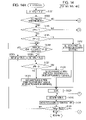
- FIG. 7 is a flowchart of a subroutine for a focus determination (step S 407 ) shown in FIG. 4 .
- FIG. 8 is a flowchart for an operation of finding monotone decreasing in a direction approaching infinity.
- FIG. 9 is a flowchart for an operation of finding monotone decreasing in a direction toward the closest point.
- FIG. 10 is an illustration for describing a concept of determination of a focus evaluated value.
- FIG. 11 is a flowchart of a subroutine for a shooting operation shown in FIGS. 2 and 13 .
- FIG. 12 illustrates how a focus lens moves according to the first exemplary embodiment.
- FIG. 13 is a flowchart for a series of operations according to second and third exemplary embodiments.
- FIGS. 14A and 14B are flowcharts of a subroutine for an AF operation according to the second exemplary embodiment.
- FIGS. 15A and 15B are flowcharts of a subroutine for an AF operation according to the third exemplary embodiment.
- FIG. 16 is a flowchart of a subroutine for a shooting operation according to the third exemplary embodiment.
- FIG. 1 is a block diagram of a main portion of an electronic camera to which the first exemplary embodiment is applied.
- the electronic camera includes an objective taking lens 101 having a zoom mechanism, an aperture and shutter 102 for controlling the amount of light, an autoexposure (AE) processing unit 103 , a focus lens 104 serving as a focusing optical system for adjusting a focal point on an image pickup element 108 , an autofocus (AF) processing unit 105 , a flash 106 , a flash pre-emission (EF) processing unit 107 , and the image pickup element 108 serving as a light detecting unit or a photoelectric conversion unit for converting light reflected from an object into an electric signal.
- the AF processing unit 105 will be described below in further detail with reference to FIG. 4 .
- the electronic camera further includes an A/D conversion unit 109 , an image processing unit 110 , a white balance (WB) processing unit 111 , a format conversion unit 112 , a high-speed internal memory 113 (e.g., random-access memory, hereinafter sometimes referred to as DRAM), an image recording unit 114 including a storage medium (e.g., a memory card) and its interface, a system control unit 115 for controlling a system, such as an imaging sequence, a memory 116 used for displaying an image (hereinafter sometimes referred to as VDRAM), an operation display unit 117 , an operation unit 118 used for externally operating the camera, a shooting mode switch 119 used for selecting a shooting mode (e.g., program, landscape, portrait, high-speed shutter, and other modes), and a drive mode switch 120 used for selecting a drive mode (e.g., single shot, burst shot (continuous), self-time, and other modes).
- a shooting mode switch 119 used for selecting a
- the continuous shooting mode is a mode of repeating image recording while an imaging switch 124 (hereinafter referred to as SW 2 ), which will be described below, is pressed and held.
- the A/D conversion unit 109 includes a correlated double sampling (CDS) circuit for reducing noise output from the image pickup element 108 and a nonlinear amplification circuit performed prior to A/D conversion.
- the operation display unit 117 displays an image, an auxiliary operation, and a state of the camera and, during an imaging operation, functions as an imaging screen and displays a distance-measured area.
- the electronic camera further includes an AF mode switch 121 , a main switch 122 used for turning on the power to the system, a switch 123 used for performing an imaging standby operation, such as AF and AE, (hereinafter referred to as SW 1 ), and the SW 2 used for performing an imaging operation after the SW 1 is operated.
- the AF mode switch 121 is used for selecting a continuous AF mode, which continues focusing on an object without the SW 1 being pushed, or a single AF mode, which focuses after a scan operation and then maintains the position of a focus lens.
- the DRAM 113 is used as a high-speed buffer as a temporary image storing unit or used as a work memory in image compression and decompression.
- the operation unit 118 may include, for example, a menu switch used for performing various settings, such as a setting for functions for shooting in an image pick up apparatus and a setting for image reproduction, a zoom lever used for providing instructions as to a zoom operation of the objective taking lens, and an operation-mode selection switch used for selecting the shooting mode or a reproducing mode.
- step S 201 the state of the main switch 122 is detected. If the state is ON, the processing proceeds to step S 202 .
- the main switch 122 functions to turn on the power to the system.
- step S 202 the remaining capacity of the image recording unit 114 is checked. If the remaining capacity is zero, the processing proceeds to step S 203 ; otherwise the processing proceeds to step S 204 .
- step S 203 a warning that the remaining capacity of the image recording unit 114 is zero is issued, and then the processing returns to step S 201 .
- the warning can be displayed on the operation display unit 117 or can be output as a warning beep emitted from an audio output unit (not shown). Alternatively, both indications can be performed as the warning.
- step S 204 it is detected whether the AF mode is the continuous AF mode or the single AF mode. If the continuous AF mode is detected, the processing proceeds to step S 205 . If the single AF mode is detected, the processing proceeds to step S 206 . In step S 205 , the continuous AF is performed in accordance with a flowchart of FIG. 3 , which will be described below.
- step S 206 the state of the SW 1 is checked. If the detected state is ON, the processing proceeds to step S 208 ; otherwise the processing proceeds to step S 207 .
- the SW 1 functions to perform the imaging standby operation (e.g., AF and AE operation).
- step S 207 the state of the main switch 122 is checked. If the detected state is ON, the processing proceeds to step S 204 ; otherwise the processing proceeds to step S 201 .
- step S 208 the AE processing unit 103 performs the AE processing in response to the output from the image processing unit 110 .
- step S 209 the AF operation is performed in accordance with a flowchart of FIG. 4 , which will be described below.
- step S 210 the state of the SW 2 is checked. If the detected state is ON, the processing proceeds to step S 212 ; otherwise the processing proceeds to step S 211 .
- the SW 2 functions to perform imaging after the SW 1 is operated.
- step S 211 the state of SW 1 is checked. If the detected state is not ON, the processing returns to step S 204 ; if the detected state is ON, the processing returns to step S 210 , in which focus is locked until the SW 2 is turned on or until the SW 1 is turned off.
- step S 212 the shooting operation is performed in accordance with a flowchart of FIG. 11 , which will be described below.
- step S 213 the remaining capacity of the image recording unit 114 is checked. If the detected remaining capacity is zero, the processing proceeds to step S 203 ; otherwise the processing proceeds to step S 214 .
- step S 214 it is checked whether the continuous shooting mode has been set (by selection via the drive mode switch 120 or as default selected via the shooting mode switch 119 ). If the continuous shooting mode has been set, the processing proceeds to step S 216 ; otherwise the processing proceeds to step S 215 .
- step S 215 a captured image is displayed on the operation display unit 117 while the SW 2 is in the ON state. If, in step S 215 , the SW 2 is in the OFF state, the processing proceeds to step S 211 .
- step S 216 if the SW 2 is not in the ON state, the processing proceeds to step S 211 . If, in step S 216 , the SW 2 is in the ON state, the processing returns to step S 209 to perform a continuous shooting operation and proceeds to the AF operation in the continuous shooting mode in accordance with the flowchart of FIG. 4 .
- FIG. 3 is a flowchart of a subroutine for the continuous AF in the flowchart of FIG. 2 (step S 205 ).
- the subroutine is performed by the AF processing unit 105 on the basis of control processing of the system control unit 115 .
- step S 301 as a result of processing of the AF processing unit 105 , a focus evaluated value is acquired.
- step S 302 the system control unit 115 determines whether a peak detection flag is TRUE. If the peak detection flag is TRUE, the processing proceeds to step S 317 ; if not, the processing proceeds to step S 303 .
- step S 303 the present position of the focus lens 104 is acquired.
- step S 304 one (1) is added to an acquisition counter used for counting acquisitions of the focus evaluated value and the present position. The acquisition counter is set at zero (0) in advance by initialization (not shown).
- step S 305 it is checked whether the value of the acquisition counter is one. If the value is one, the processing proceeds to step S 307 ; if the value is not one, the processing proceeds to step S 306 .
- step S 306 it is checked whether “the current focus evaluated value” is larger than “the previous focus evaluated value”. If “the current focus evaluated value” is larger than “the previous focus evaluated value”, the processing proceeds to step S 307 ; otherwise the processing proceeds to step S 313 .
- step S 307 the current focus evaluated value is stored in a calculation memory (not shown) incorporated in the system control unit 115 as the maximum value of the focus evaluated value.
- step S 308 the present position of the focus lens 104 is stored in the calculation memory (not shown) incorporated in the system control unit 115 as the peak position of the focus evaluated value.
- step S 309 the current focus evaluated value is stored in the calculation memory (not shown) incorporated in the system control unit 115 as the previous focus evaluated value.
- step S 310 it is checked whether the present position of the focus lens 104 lies at the end of a measured scan range. If the present position of the focus lens 104 lies at the end of the scan range, the processing proceeds to step S 311 ; otherwise the processing proceeds to step S 312 .
- step S 311 the direction of movement of the focus lens 104 is inverted.
- step S 312 a signal for moving the focus lens 104 by a predetermined amount is output.
- step S 313 it is checked whether a value of “the maximum value of the focus evaluated value—the current focus evaluated value” is larger than a predetermined amount. If the value of “the maximum value of the focus evaluated value—the current focus evaluated value” is larger than the predetermined amount, the processing proceeds to step S 314 ; otherwise the processing proceeds to step S 309 . If the value of “the maximum value of the focus evaluated value—the current focus evaluated value” is larger than the predetermined amount, i.e., the current focus evaluated value decreases from the maximum value by the predetermined amount or more, the peak position corresponding to the maximum value is considered as a focus position.
- step S 314 the focus lens 104 is moved to the peak position corresponding to the maximum value of the focus evaluated value stored in step S 308 .
- step S 315 the peak detection flag is set at TRUE.
- step S 316 the acquisition counter is set at zero.
- step S 317 the system control unit 115 checks whether the current focus evaluated value has varied from the maximum value of the focus evaluated value by a predetermined ratio or more. If the current focus evaluated value has greatly varied by the predetermined ratio or more, the processing proceeds to step S 319 ; if the current focus evaluated value has varied by a little, the processing proceeds to step S 318 .
- step S 318 the focus lens 104 is maintained at the current position.
- step S 319 in order to recalculate the position of the focus lens 104 where the focus evaluated value is highest, the peak detection flag is set at FALSE, and the maximum value of the focus evaluated value and the peak position corresponding thereto are reset.
- the continuous AF operation drives the focus lens 104 so that the focus lens 104 is continuously in focus.
- FIG. 4 is a flowchart of a subroutine for the AF operation in the flowchart of FIG. 2 (step S 209 ).
- the subroutine is performed on the basis of the control processing of the system control unit 115 .
- FIG. 5 illustrates a method for setting a scan range.
- the horizontal axis represents the number of imaging times
- the vertical axis represents the position of the focus lens.
- step S 401 it is checked whether the continuous shooting mode has been set (by selection via the drive mode switch 120 or as default selected via the shooting mode switch 119 ). If the continuous shooting mode has been set, the processing proceeds to step S 412 ; otherwise the processing proceeds to step S 402 .
- step S 402 it is checked whether the AF mode selected by the AF mode switch 121 is the continuous AF mode or the single AF mode. If the detected AF mode is the continuous AF mode, the processing proceeds to step S 403 ; if not, the processing proceeds to step S 405 .
- step S 403 it is checked whether the peak detection flag in the flowchart of FIG. 3 is TRUE. If the peak detection flag is TRUE, the processing proceeds to step S 404 ; if not, the processing proceeds to step S 405 .
- step S 404 with the main aim of improving the accuracy of focusing, a scan range that has a predetermined narrow scan width centered about the present position of the focus lens is set. This is because, due to the continuous AF operation, the focus lens lies adjacent to the focus position, at which the focus evaluated value is highest.
- the scan range is set in step S 404 so as to satisfy the number of scan data required for the focus determination performed in accordance with a flowchart of FIG. 7 , which will be described below, and so as not to have an unnecessary long length of a scan time.
- the speed of the focus lens during scanning may vary from one scan to another. For example, a scan operation in a side adjacent to a closest point can have a higher speed of the focus lens because the image plane velocity is higher at the side adjacent to the closest point.
- step S 405 all scannable area corresponding to a selected mode is set as the scan range.
- step S 406 a scan operation over the scan range set in step S 404 or S 405 is performed in accordance with a flowchart of FIG. 6 , which will be described below.
- step S 407 the focus determination is performed in accordance with a flowchart of FIG. 7 , which will be described below, in response to the focus state acquired in step S 406 .
- step S 408 if the result of the focus determination in step S 407 is “ ⁇ ”, the processing proceeds to step S 409 ; if the result is “x”, the processing proceeds to step S 410 .
- step S 410 it is checked whether scanning of all scannable area in a selected mode has been completed. If the scanning has been completed, the processing proceeds to step S 411 ; if the scanning has not been completed, the processing returns to step S 405 .
- step S 409 the focus lens 104 is moved to a peak position calculated in the scan operation in step S 406 or in step S 418 , which will be described below.
- step S 411 the focus lens 104 is moved to a preset position called a fixed point.
- the above-described AF operation corresponds to an AF operation that is performed when the continuous shooting mode is not selected and varies the settings of the scan range depending on the selected AF mode (continuous AF mode or single AF mode).
- an AF operation performed when the continuous shooting mode is selected is described below.
- step S 412 the system control unit 115 checks whether the current imaging operation is a first one in a continuous shooting operation. If the current imaging operation is the first one, the processing proceeds to step S 403 ; otherwise the processing proceeds to step S 413 .
- the AF operation is the same as in the continuous AF. This intends to reduce a release time lag by setting a narrower scan range in step S 404 than that set via step S 405 .
- step S 413 the system control unit 115 checks whether the current imaging operation is a second one in the continuous shooting operation. If the current imaging operation is the second one, the processing proceeds to step S 414 ; otherwise the processing proceeds to step S 415 .
- step S 414 the position of the focus lens 104 in the first imaging operation (peak position “FP 1 ”) is set as a center position “ObjP 2 ” as a datum point of the scan range. The scan range is set so that not increasing the time intervals between continuous imaging operations is prioritized.
- the scan range is set so that the AF operation is completed in an interval between continuous imaging operations in consideration of the time required for performing processing within the time interval between the continuous imaging operations, for example, the time required for reading an image signal from the image pickup element and the time required for checking the next imaging operation.
- step S 415 the system control unit 115 checks whether the current imaging operation is a third one in the continuous shooting operation. If the current imaging operation is the third one, the processing proceeds to step S 416 ; otherwise the processing proceeds to step S 417 .
- the parameter FpAdj(n) is a parameter for assigning weights to the result of the prediction of the object distance and the immediately preceding focus position and takes on values from 0 to 1.
- FpAdj(n) is one (1).
- the scan range is set on the basis of the calculated center position ObjP 3 , so that the scan range is shifted from the previous scan range toward a direction in which an object's image moves.
- a center position “ObjP 4 ” as a datum point of the scan range is calculated by prediction of an object distance (peak position for the current imaging operation) by a second order approximation represented by expression (2):
- the scan range is set on the basis of the calculated center position ObjP 4 , so that the scan range is shifted from the previous scan range toward a direction in which an object's image moves.
- each of the respective center positions ObjP(n) as a datum point of each of the respective scan ranges is calculated by prediction of an object distance (peak position for the current imaging operation) by a second order approximation represented by expression (3):
- ObjP ( n ) ( FP ( n ⁇ 1) ⁇ 3 FP ( n ⁇ 2)+2 FP ( n )) ⁇ FpAdj ( n )+ FP ( n ⁇ 1)
- the scan range is set on the basis of the calculated center position ObjP(n), so that the scan range is shifted from the previous scan range toward a direction in which an object's image moves.
- step S 418 scan is performed in accordance with the flowchart of FIG. 6 , which will be described below.
- the focus lens 104 is moved to the peak position (this may be a peak position for the previous imaging operation).
- the focus determination in step S 407 is not performed. This is because, even if the result of the focus determination in the flowchart of FIG. 7 is “x”, an imaging operation performed at the peak position for the previous imaging operation is more likely to have reduced blurring than an imaging operation performed after the focus lens 104 is driven to a fixed point.
- the processing shifts to a mode that is the same as the continuous AF mode.
- the center position for the first imaging operation can be calculated by performing the following processing in the continuous shooting mode. That is, it is set in advance that, in the case where the continuous shooting mode has been set, in step S 204 in FIG. 2 , the processing shifts to the continuous AF mode.
- the center position can be predicted from the first imaging operation in the continuous shooting operation by calculation based on information on the previous focused focal point before the SW 1 .
- FIG. 6 is a flowchart of a subroutine for the scan operation in the flowchart of FIG. 4 (steps S 406 and S 418 ).
- the subroutine is performed on the basis of the control processing of the system control unit 115 .
- step S 601 the focus lens 104 is moved to a scan start position at a speed that is higher than a speed during scan operation.
- the scan start position is set at a first end of a set scan range. Unlike the first exemplary embodiment, the scan start position can be a point other than the end of the scan range. In this case, however, the scan operation may require a longer time accordingly.
- step S 602 a focus evaluated value for an area corresponding to an AF frame set in an imaging region and the position of the focus lens 104 are stored in a calculation memory (not shown) incorporated in the system.
- step S 603 it is checked whether the position of the focus lens 104 is a scan end position. If the position of the focus lens 104 is the scan end position, the processing proceeds to step S 605 ; otherwise the processing proceeds to step S 604 .
- the scan end position is set at a second end of the set scan range.
- the focus lens 104 is driven and moved in a predetermined direction by a predetermined amount.
- step S 605 on the basis of the focus evaluated value and the position of the focus lens 104 stored in step S 602 , a peak position of the focus lens 104 that corresponds to the maximum value of the focus evaluated value is calculated.
- FIG. 12 illustrates how the focus lens moves during a continuous shooting operation over time.
- the system control unit 115 controls the focus lens so that the focus lens moves from a present position a 1 thereof to a scan start position a 2 at a speed that is higher than a speed during scan operation. Then, the scan operation starts from the scan start position a 2 . The focus lens stops at the peak position FP 1 .
- the system control unit 115 controls the focus lens so that the focus lens moves from a present position b 1 thereof as being the peak position FP 1 to a scan start position b 2 at a speed that is higher than a speed during the scan operation.
- the focus lens is moved from a present position c 1 thereof as being the peak position FP 2 for the second imaging operation to a scan start position c 2 calculated by the above-described manner at high speed.
- the focus lens is moved from a position d 1 to a position d 2 at a speed that is higher than a speed during the subsequent scan operation. Therefore, a sufficient scan range can be maintained and, even when an object distance largely varies, focusing can track an object with high precision.
- step S 407 A subroutine for the focus determination shown in the flowchart of FIG. 4 (step S 407 ) is described below with reference to FIGS. 7 to 10 .
- FIG. 10 illustrates a hill-shaped focus state, with the horizontal axis representing the position of the focus lens and the vertical axis representing the focus evaluated value. It is determined whether the focus evaluated value exhibits a hill-shaped state like this, on the basis of the difference between the maximum value and the minimum value of the focus evaluated value, the length of a segment that is inclined at a slope of a constant value (SlopeThr) or more, and the slope of the inclined segment.
- the focus determination is performed by this processing.
- the result of the focus determination is output as “ ⁇ ” or “x”, which will be described below.
- the mark “ ⁇ ” represents that an object can be focused from a position corresponding to the peak position of the focus evaluated value.
- the mark “x” represents that the contrast of an object is insufficient or that an object lies in an area other than a scanned range.
- points to which the inclination from the top of a hill (point A) continues are defined as points D and E
- the distance between the points D and E is defined as the width of the hill L
- the difference between the focus evaluated values at the points A and D is defined as SL 1
- the difference between the focus evaluated values at the points A and E is defined as SL 2
- the sum of SL 1 and SL 2 is defined as SL.
- FIG. 7 is a flowchart of a subroutine for the focus determination shown in the flowchart of FIG. 4 (step S 407 ).
- the subroutine is performed on the basis of control processing of the system control unit 115 .
- step S 701 a maximum value, max, of a focus evaluated value, a minimum value, min, thereof, and a scan point, io, for providing the maximum value are found.
- step S 702 a variable L, which represents the width of a hill of the focus evaluated value, and a variable SL, which represents the slope of the hill, are reset to zero.
- step S 703 it is checked whether the scan point io, which provides the maximum value, lies at an end adjacent infinity in a scanned predetermined range. If the scan point io does not lie at the end adjacent to infinity, the processing proceeds to step S 704 , in which monochrome decreasing in a direction approaching infinity is checked. If the scan point io lies at the end adjacent to infinity, the processing skips this process and proceeds to step S 705 .
- FIG. 8 shows a flowchart of the process.
- step S 801 a counter variable i is reset to io.
- step S 802 the difference between the value, d[i], of the focus evaluated value at the scan point i and the value, d[i ⁇ 1], of the focus evaluated value at a scan point i ⁇ 1, which is shifted toward infinity by one scan point, is compared with a predetermined value SlopeThr. If d[i] ⁇ d[i ⁇ 1] ⁇ SlopeThr, it is determined that monochrome decreasing in the direction approaching infinity has occurred and the processing proceeds to step S 803 .
- step S 705 it is checked whether the scan point io, which provides the maximum value, lies at an end adjacent to a closest point in a scanned predetermined range. If the scan point io does not lies at the end adjacent to the closest point, the processing proceeds to step S 706 , in which monochrome decreasing in a direction toward the closest point is checked. If the scan point io lies at the end adjacent to the closest point, the processing skips this process and proceeds to step S 707 .
- FIG. 9 shows a flowchart of the process.
- step S 901 a counter variable i is reset to io.
- step S 902 the difference between the value d[i] of the focus evaluated value at the scan point i and the value, d[i+1], of the focus evaluated value at a scan point i+1, which is shifted toward the closest point by one scan point, is compared with the predetermined value SlopeThr. If d[i] ⁇ d[i+1] ⁇ SlopeThr, it is determined that monochrome decreasing in the direction toward the closest point has occurred and the processing proceeds to step S 903 .
- step S 707 if the scan point io, which provides the maximum value of the focus evaluated value, lies at the end adjacent to the closest point in a scanned predetermined range and the difference between the value, d[n], of the focus evaluated value at a scan point n being the end adjacent to the closest point in the scan range and the value, d[n ⁇ 1], of the focus evaluated value at a scan point n ⁇ 1, which is shifted toward infinity by one scan point, is equal to or larger than the predetermined value SlopeThr, the processing proceeds to step S 711 . Otherwise the processing proceeds to step S 708 .
- step S 708 if the scan point io, which provides the maximum value of the focus evaluated value, lies at the end adjacent to infinity in a scanned predetermined range and if the difference between the value, d[ 0 ], of the focus evaluated value at a scan point 0 being the end adjacent to infinity in the scan range and the value, d[ 1 ], of the focus evaluated value at a scan point 1 , which is shifted from the scan point 0 toward the closest point by one scan point, is equal to or larger than the predetermined value SlopeThr, the processing proceeds to step S 711 . Otherwise the processing proceeds to step S 709 .
- step S 709 if the length L, which is the length of a segment that is inclined at a slope of a constant value or more, is equal to or larger than a predetermined value Lo, the mean value, SL/L, of the slope in the inclined segment is equal to or larger than a predetermined value SLo/Lo, and the difference between the maximum and minimum values of the focus evaluated value is equal to or larger than a predetermined value, the processing proceeds to step S 710 . Otherwise the processing proceeds to step S 711 . In step S 710 , since a hill-shaped focus evaluated value is acquired and thus focusing on an object is obtainable, the determination results in “ ⁇ ”. In step S 711 , since an acquired focus evaluated value is not hill-shaped and thus focusing on an object is not obtainable, the determination results in “x”.
- step S 407 in the flowchart of FIG. 4 is performed.
- FIG. 11 is a flowchart of a subroutine for the shooting operation in the flowchart of FIG. 2 (step S 212 ).
- the subroutine is performed on the basis of control processing of the system control unit 115 .
- step S 1101 the brightness of an object is measured.
- step S 1102 in response to the brightness of the object measured in step S 1101 , the image pickup element 108 is exposed. An image formed on the surface of the image pickup element 108 is photoelectrically converted into an analog signal.
- step S 1103 the analog signal is sent to the A/D conversion unit 109 , and it is converted into a digital signal after being subjected to pre-processing, such as noise reduction of noise output from the image pickup element 108 and nonlinear processing.
- step S 1104 the white balance of a signal output from the A/D conversion unit 109 is adjusted by the WB processing unit 111 , and the signal is processed so as to be a proper output image signal in the image processing unit 110 .
- step S 1105 the format of the output image signal is converted into the JPEG format or other formats by the format conversion unit 112 , and it is temporarily stored in the DRAM 113 .
- step S 1106 data in the DRAM 113 is transferred to an external storage medium, such as a memory in the camera or a memory card mounted in the camera, and is stored therein.
- Setting the scan width in a narrow range is not limited to setting a uniform scan width. For example, if the scan center position determined by prediction of an object is remote from the immediately preceding imaging position, because the amount of movement of the object is determined to be large, it may be effective to increase the scan width within a range in which the AF operation can be completed in the time interval between continuous imaging operations. If focus is prioritized and the time interval between continuous imaging operations is allowed to be expanded, setting the scan width is not limited to the above-described setting.
- the center position ObjP(n) in the scan range is calculated.
- the center position of the scan range can be replaced with any position as long as the position is a datum point for defining the scan range. For example, a position that is displaced from the center position of the scan range toward a far side by a predetermined position may be calculated. A datum point suited for calculation can be used.
- the scan range may be determined from a period of time of a scanning operation and a speed of a focus lens during the scanning.
- a focusing technique described in the first exemplary embodiment predicts the movement of an object on the basis of historical information on past focus positions. At this time, by calculation of the center position of a scan range, the focusing technique can have an improved capability of tracking a moving object.
- FIG. 13 is a flowchart for a series of operations of an electronic camera according to the second exemplary embodiment.
- step S 1201 the state of the main switch 122 is detected. If the detected state is ON, the processing proceeds to step S 1202 .
- the main switch 122 functions to turn on the power to the system.
- step S 1202 the remaining capacity of the image recording unit 114 is checked. If the detected remaining capacity is zero, the processing proceeds to step S 1203 ; otherwise the processing proceeds to step S 1204 .
- step S 1203 a warning that the remaining capacity of the image recording unit 114 is zero is issued, and then the processing returns to step S 1201 .
- the warning can be displayed on the operation display unit 117 or output as a warning beep emitted from an audio output unit (not shown). Alternatively, both indications can be performed as the warning.
- step S 1204 as a result of determining that the remaining capacity of the image recording unit 114 is not zero in S 1202 , it is checked whether the AF mode is the continuous AF mode or the single AF mode. If the continuous AF mode is detected, the processing proceeds to step S 1205 . If the single AF mode is detected, the processing proceeds to step S 1206 . In step S 1205 , the continuous AF mode is performed in accordance with the flowchart of FIG. 3 .
- next step S 1206 the state of the SW 1 is checked. If the detected state is ON, the processing proceeds to step S 1208 ; otherwise the processing proceeds to step S 1207 .
- the SW 1 functions to perform the imaging standby operation (e.g., AF and AE operation).
- step S 1207 the state of the main switch 122 is checked. If the detected state is ON, the processing returns to step S 1204 ; otherwise the processing returns to step S 1201 .
- step S 1208 the AE processing unit 103 performs the AE processing on the basis of the output from the image processing unit 110 .
- step S 1210 the AF operation is performed in accordance with flowcharts of FIGS. 14A and 14B , which will be described below.
- step S 1211 the state of the SW 2 is checked. If the detected state is ON, the processing proceeds to step S 1214 ; otherwise the processing proceeds to step S 1212 .
- the SW 2 functions to perform imaging after the SW 1 is operated.
- step S 1214 as a result of determining that the SW 2 is in the ON state in step S 1211 , the shooting operation is performed in accordance with the flowchart of FIG. 11 .
- step S 1215 the remaining capacity of the image recording unit 114 is checked. If the detected remaining capacity is zero, the processing proceeds to step S 1203 ; otherwise the processing proceeds to step S 1216 .
- step S 1216 it is checked whether the continuous shooting mode has been set (by selection via the drive mode switch 120 or as default selected via the shooting mode switch 119 ). If the continuous shooting mode has been set, the processing proceeds to step S 1218 ; otherwise the processing proceeds to step S 1217 .
- step S 1217 a captured image is displayed on the operation display unit 117 while the SW 2 is in the ON state. If, in step S 1217 , the SW 2 is in the OFF state, the processing proceeds to step S 1212 . In step S 1218 , if the SW 2 is not in the ON state, the processing proceeds to step S 1212 . If, in step S 1218 , the SW 2 is in the ON state, the processing proceeds to step S 1210 to perform a continuous shooting operation and proceeds to the AF operation in the continuous shooting mode in accordance with flowcharts of FIGS. 14A and 14B , which will be described below.
- a subroutine for the AF operation in step S 1210 in FIG. 13 is described below with reference to the flowcharts of FIGS. 14A and 14B .
- step S 1302 it is checked whether the continuous shooting mode has been set (by selection via the drive mode switch 120 or as default selected via the shooting mode switch 119 ). If the continuous shooting mode has been set, the processing proceeds to step S 1315 ; otherwise the processing proceeds to step S 1303 .
- step S 1303 it is checked whether the AF mode selected by the AF mode switch 121 is the continuous AF mode or the single AF mode. If the detected AF mode is the continuous AF mode, the processing proceeds to step S 1304 ; if it is the single AF mode, the processing proceeds to step S 1306 .
- step S 1304 it is checked whether the peak detection flag in the flowchart of FIG. 3 is TRUE. If the peak detection flag is TRUE, the processing proceeds to step S 1305 ; if it is FALSE, the processing proceeds to step S 1306 .
- step S 1305 since the focus lens 104 lies adjacent to the focus position, at which the focus evaluated value is highest, due to the continuous AF operation, with the main aim of improving the accuracy of focusing, a narrow scan range centered about the present position of the focus lens is set.
- the scan range is set so as to satisfy the number of scan data required for the focus determination performed in accordance with the flowchart of FIG. 7 and so as not to have an unnecessary long length of a scan time.
- all scannable area corresponding to a selected mode is set as the scan range.
- next step S 1307 a scan operation over the scan range set in step S 1305 or S 1306 is performed in accordance with the flowchart of FIG. 6 .
- next step S 1308 the focus determination is performed on the basis of scan data stored in step S 1307 in accordance with the flowchart of FIG. 7 .
- next step S 1309 if the result of the focus determination in step S 1308 is “ ⁇ ”, the processing proceeds to step S 1310 .
- step S 1311 the focus lens 104 is moved to a peak position calculated in the scan operation in step S 1307 or in step S 1324 , which will be described below. Then the processing proceeds to step S 1325 , which will be described below.
- step S 1302 the continuous shooting mode has been set, the processing proceeds to step S 1315 , as described above.
- step S 1315 it is checked whether AFN, which represents the number of AF operations in a continuous shooting operation, is one. If AFN is one, the processing proceeds to step S 1304 ; if AFN is not one, the processing proceeds to step S 1316 .
- the AF operation is the same as in the continuous AF because it is impossible to predict an object on the basis of historical data on past focus positions. This intends to reduce a release time lag by setting a narrower scan range in step S 1305 . Accordingly, in the continuous shooting mode, it is useful that the continuous AF mode is set as default.
- step S 1317 the position of the focus lens 104 in the first imaging operation is set as a center position of the scan range.
- the maximum width of the scan range is a scan width in which the AF operation is completed within an interval between continuous imaging operations in a state where the DRAM 113 used as a buffer has sufficient available capacity.
- the maximum width of the scan range described above is set.
- the total sum of the time required for acquiring the number of scan data enabling the focus determination in the flowchart of FIG. 7 , the time required for moving to a scan start position, the time required for moving to a focus position after the completion of scanning, and the time required for performing various computations is set so as to be smaller than each of the time intervals between continuous imaging operations.
- the parameter FpAdj(n) is a parameter for assigning weights to the result of the prediction of the object and the immediately preceding focus position and takes on values from 0 to 1. For the position of the focus position shown in FIG. 5 , FpAdj(n) is one.
- step S 1323 since information on at least three previous focus positions (FP 1 , FP 2 , and FP 3 ) as the focus-position historical information exists, the center position ObjP 4 of the scan range is calculated by prediction of an object by a second order approximation represented by expression (4):
- step S 1324 a scan operation is performed in accordance with the flowchart of FIG. 6 , and the processing proceeds to step S 1310 .
- the focus determination is not performed. This is because, even if the result of the focus determination in the flowchart of FIG. 7 is “x”, an imaging operation at the peak position for the previous imaging operation is more likely to have reduced blurring than an imaging operation after the focus lens 104 is driven to a fixed point. At the same time, focus is not displayed.
- the above scan range is set so that the number of scan points required for a focus determination described below is satisfied and so that the time required for scanning is not unnecessary long.
- the camera can track a moving object in the next imaging operation by performing the AF scan operation at regular time intervals and can continue prediction of the moving object.
- the second exemplary embodiment describes exemplary processing for a state in which, in the case where the time interval to the next imaging operation is inevitably increased in the middle of a continuous shooting operation performed at regular time intervals, the AF operation can be performed by the time the next imaging operation starts. However, if the AF operation cannot be performed by the time the next imaging operation starts (for example, if a buffer memory is full), it is impossible to perform prediction of a moving object even when the second exemplary embodiment is used.
- the third exemplary embodiment describes exemplary processing for a state in which the time interval to the next imaging operation is inevitably increased in the middle of a continuous shooting operation performed at regular time intervals and the AF operation cannot be performed by the time the next imaging operation starts.
- the third exemplary embodiment is different from the second exemplary embodiment only in the AF operation in step S 1210 and the shooting in step S 1214 in FIG. 13 in the second exemplary embodiment.
- FIGS. 15A and 15B are flowcharts of processes for the AF operation of the electronic camera according to the third exemplary embodiment.
- step S 1401 it is checked whether the continuous shooting mode has been set (by selection via the drive mode switch 120 or as default selected via the shooting mode switch 119 ). If the continuous shooting mode has been set, the processing proceeds to step S 1412 ; otherwise the processing proceeds to step S 1402 .
- step S 1402 it is checked whether the AF mode selected by the AF mode switch 121 is the continuous AF mode or the single AF mode. If the detected AF mode is the continuous AF mode, the processing proceeds to step S 1403 ; if it is the single AF mode, the processing proceeds to step S 1405 .
- step S 1403 it is checked whether the peak detection flag in the flowchart of FIG. 3 is TRUE. If the peak detection flag is TRUE, the processing proceeds to step S 1404 ; if it is FALSE, the processing proceeds to step S 1405 .
- step S 1404 since the focus lens 104 lies adjacent to the focus position, at which the focus evaluated value is highest, due to the continuous AF operation, with the main aim of improving the accuracy of focusing, a narrow scan range centered about the present position of the focus lens is set.
- the scan range is set so as to satisfy the number of scan data required for the focus determination performed in accordance with the flowchart of FIG. 7 and so as not to have an unnecessary long length of a scan time.
- all AF performable area corresponding to a selected mode is set as the scan range.
- next step S 1406 a scan operation over the scan range set in step S 1404 or S 1405 is performed in accordance with the flowchart of FIG. 6 .
- next step S 1407 the focus determination is performed on the basis of scan data stored in step S 1406 in accordance with the flowchart of FIG. 7 .
- next step S 1408 if the result of the focus determination in step S 1407 is “ ⁇ ”, the processing proceeds to step S 1409 ; if the result is “x”, the processing proceeds to step S 1410 .
- step S 1410 it is checked whether scanning of all AF performable area corresponding to a selected mode has been completed.
- step S 1411 the focus lens 104 is moved to a preset position called a fixed point.
- step S 1409 the focus lens 104 is moved to a peak position calculated in the scan operation in step S 1406 or in step S 1421 , which will be described below.
- step S 1422 the processing proceeds to step S 1422 , which will be described below.
- the AF operation is the same as in the continuous AF because it is impossible to predict an object on the basis of historical data on past focus positions. This intends to reduce a release time lag by setting a narrower scan range in step S 1404 . Accordingly, in the continuous shooting mode, it is useful that the continuous AF mode is set as default.
- step S 1416 the position of the focus lens 104 in the first imaging operation is set as a center position of the scan range.
- the maximum width of the scan range is a scan width in which the AF operation is completed within an interval between continuous imaging operations in a state where the DRAM 113 used as a buffer has sufficient available capacity.
- the maximum width of the scan range described above is set.
- the total sum of the time required for acquiring the number of scan data enabling the focus determination in the flowchart of FIG. 7 , the time required for moving to a scan start position, the time required for moving to a focus position after the completion of scanning, and the time required for performing various computations is set so as to be smaller than each of the time intervals between continuous imaging operations.
- the parameter FpAdj(n) is a parameter for assigning weights to the result of the prediction of the object and the immediately preceding focus position and takes on values from 0 to 1. For the position of the focus position show in FIG. 5 , FpAdj(n) is one.
- step S 1419 since information on at least three previous focus positions (FP 1 , FP 2 , and FP 3 ) as the focus-position historical information exists, the center position ObjP 4 of the scan range is calculated by prediction of an object by a second order approximation represented by expression (6):
- step S 1420 since the DRAM 113 is full (no available space) and thus the time interval between the current imaging operation and the immediately preceding imaging operation is longer than the time interval between the previous two imaging operations in the focus-position historical information, information on the previous two focus positions cannot be used in approximation expression. Accordingly, the position of the focus lens in the immediately preceding imaging operation is set as the center of the scan range. In addition, since prediction of a moving object is impossible, the scan range at this time is expanded from the scan range in steps S 1418 and S 1419 by ⁇ times ( ⁇ >1) so that the camera can track the moving object.
- step S 1421 a scan operation is performed in accordance with the flowchart of FIG. 6 , and the processing proceeds to step S 1409 .
- step S 1409 the focus lens 104 is moved to the peak position.
- the focus determination is not performed. This is because, even if the result of the focus determination in the flowchart of FIG. 7 is “x”, an imaging operation at the peak position for the previous imaging operation is more likely to have reduced blurring than an imaging operation after the focus lens 104 is driven to a fixed point. At the same time, focus is not displayed.
- FIG. 16 is a flowchart of the shooting operation of the electronic camera according to the third exemplary embodiment.
- step S 1501 BlFlg is set at FALSE where BfFlg represents whether the DRAM 113 is full.
- step S 1502 the brightness of an object is measured.
- step S 1503 in response to the brightness of the object measured in step S 1502 , the image pickup element 108 is exposed. An image formed on the surface of the image pickup element 108 is photoelectrically converted into an analog signal.
- step S 1504 the analog signal is sent to the A/D conversion unit 109 , and it is converted into a digital signal after being subjected to pre-processing, such as noise reduction of noise output from the image pickup element 108 and nonlinear processing.
- step S 1505 the white balance of a signal output from the A/D conversion unit 109 is adjusted by the WB processing unit 111 , and the signal is processed so as to be a proper output image signal in the image processing unit 110 .
- step S 1506 the format of the output image signal is converted into the JPEG format or other formats by the format conversion unit 112 , and it is temporarily stored in the DRAM 113 .
- step S 1507 it is checked whether the DRAM 113 is full. If the DRAM 113 is full, the processing proceeds to step S 1509 ; if the DRAM 113 has sufficient available capacity, the subroutine for the shooting operation is completed.
- step S 1510 data in the DRAM 113 is transferred to an external storage medium, such as a memory in the camera or a memory card mounted in the camera, and is stored therein.
- the camera can track a moving object by expanding a scan range of the focus lens 104 . Therefore, even in such a case, the camera can track the moving object at the next imaging operation and can continue prediction of the moving object.
Landscapes
- Physics & Mathematics (AREA)
- General Physics & Mathematics (AREA)
- Automatic Focus Adjustment (AREA)
- Studio Devices (AREA)
Abstract
Description
ObjP3=FP2+(FP2−FP1)×FpAdj3 (1)
The parameter FpAdj(n) is a parameter for assigning weights to the result of the prediction of the object distance and the immediately preceding focus position and takes on values from 0 to 1. For the position of the focus position shown in
ObjP4=(FP1−3FP2+3FP3)×FpAdj4+FP3(1−FpAdj4)=(FP1−3FP2+2FP3)×FpAdj4+FP3 (2)
The scan range is set on the basis of the calculated center position ObjP4, so that the scan range is shifted from the previous scan range toward a direction in which an object's image moves. Similarly, for the fifth and subsequent continuous imaging operations, each of the respective center positions ObjP(n) as a datum point of each of the respective scan ranges is calculated by prediction of an object distance (peak position for the current imaging operation) by a second order approximation represented by expression (3):
ObjP(n)=(FP(n−1)−3FP(n−2)+2FP(n))×FpAdj(n)+FP(n−1) (3)
The scan range is set on the basis of the calculated center position ObjP(n), so that the scan range is shifted from the previous scan range toward a direction in which an object's image moves. In step S418, scan is performed in accordance with the flowchart of
L=L+1
SL=SL+(d[i]−d[i−1])
If, in step S802, d[i]−d[i−1]<SlopeThr, it is determined that monochrome decreasing in the direction approaching infinity has not occurred, the process of checking monochrome decreasing in the direction approaching infinity is completed, and the processing proceeds to step S705.
L=L+1
SL=SL+(d[i]−d[i+1])
If, in step S902, d[i]−d[i+1]<SlopeThr, it is determined that monochrome decreasing in the direction toward the closest point has not occurred, the process of checking monochrome decreasing in the direction toward the closest point is completed, and the processing proceeds to step S707.
ObjP3=FP2+(FP2−FP1)×FpAdj3 (3)
ObjP3=FP2+(FP2−FP1)×FpAdj3 (5)
Claims (6)
Applications Claiming Priority (4)
| Application Number | Priority Date | Filing Date | Title |
|---|---|---|---|
| JP2006025913A JP2007206433A (en) | 2006-02-02 | 2006-02-02 | Focus adjustment apparatus, imaging apparatus, and control method |
| JP2006-025913 | 2006-02-02 | ||
| JP2006042450A JP4194604B2 (en) | 2006-02-20 | 2006-02-20 | Automatic focusing device and imaging device |
| JP2006-042450 | 2006-02-20 |
Publications (2)
| Publication Number | Publication Date |
|---|---|
| US20070177862A1 US20070177862A1 (en) | 2007-08-02 |
| US7634185B2 true US7634185B2 (en) | 2009-12-15 |
Family
ID=38322190
Family Applications (1)
| Application Number | Title | Priority Date | Filing Date |
|---|---|---|---|
| US11/668,833 Expired - Fee Related US7634185B2 (en) | 2006-02-02 | 2007-01-30 | Focusing device, image pickup apparatus, and control method |
Country Status (1)
| Country | Link |
|---|---|
| US (1) | US7634185B2 (en) |
Cited By (5)
| Publication number | Priority date | Publication date | Assignee | Title |
|---|---|---|---|---|
| US20090103885A1 (en) * | 2007-10-15 | 2009-04-23 | Canon Kabushiki Kaisha | Moving image reproducing apparatus and processing method therefor |
| US20100073549A1 (en) * | 2008-09-19 | 2010-03-25 | Hoya Corporation | Digital camera having autofocus capability and continuous shooting capability |
| US20120062786A1 (en) * | 2010-09-14 | 2012-03-15 | Canon Kabushiki Kaisha | Focus adjustment apparatus |
| US20120236198A1 (en) * | 2011-03-18 | 2012-09-20 | Samsung Electronics Co., Ltd. | Auto-focusing apparatus |
| US9667856B2 (en) | 2011-08-05 | 2017-05-30 | Samsung Electronics Co., Ltd. | Auto focus adjusting method, auto focus adjusting apparatus, and digital photographing apparatus including the same |
Families Citing this family (9)
| Publication number | Priority date | Publication date | Assignee | Title |
|---|---|---|---|---|
| JP4999641B2 (en) * | 2007-11-02 | 2012-08-15 | 富士フイルム株式会社 | Imaging apparatus and method |
| JP5134476B2 (en) * | 2008-09-16 | 2013-01-30 | キヤノン株式会社 | Imaging apparatus and control method thereof |
| JP5213813B2 (en) * | 2009-08-18 | 2013-06-19 | キヤノン株式会社 | IMAGING DEVICE AND IMAGING DEVICE CONTROL METHOD |
| CN102445812B (en) * | 2010-10-13 | 2013-10-16 | 致茂电子(苏州)有限公司 | High-speed auto-focusing method |
| US9036075B2 (en) * | 2011-11-14 | 2015-05-19 | Canon Kabushiki Kaisha | Image pickup apparatus, method for controlling the same, and storage medium |
| JP6012973B2 (en) | 2012-02-06 | 2016-10-25 | オリンパス株式会社 | Focus adjustment device, camera system, and focus adjustment method |
| US9438785B2 (en) * | 2012-03-09 | 2016-09-06 | Htc Corporation | Electronic device and focus adjustment method thereof |
| WO2015083356A1 (en) * | 2013-12-04 | 2015-06-11 | 旭化成エレクトロニクス株式会社 | Camera module adjustment method, lens position control device, control device and control method for linear motion device |
| CN105450920B (en) * | 2014-08-19 | 2019-10-11 | 宇龙计算机通信科技(深圳)有限公司 | A kind of photographic method and device |
Citations (5)
| Publication number | Priority date | Publication date | Assignee | Title |
|---|---|---|---|---|
| US4908645A (en) | 1988-02-05 | 1990-03-13 | Canon Kabushiki Kaisha | Automatic focus adjusting device |
| US5732288A (en) * | 1994-08-09 | 1998-03-24 | Nikon Corporation | Auto-focusing device for camera |
| JP2002122773A (en) | 2000-10-13 | 2002-04-26 | Olympus Optical Co Ltd | Focusing unit, electronic camera and focusing method |
| EP1322110A2 (en) | 2001-12-20 | 2003-06-25 | Canon Kabushiki Kaisha | Focus adjusting apparatus, image sensing apparatus, focusing method, program, and storage medium |
| US20050185948A1 (en) * | 2000-03-23 | 2005-08-25 | Masashi Saito | Electronic still camera |
-
2007
- 2007-01-30 US US11/668,833 patent/US7634185B2/en not_active Expired - Fee Related
Patent Citations (7)
| Publication number | Priority date | Publication date | Assignee | Title |
|---|---|---|---|---|
| US4908645A (en) | 1988-02-05 | 1990-03-13 | Canon Kabushiki Kaisha | Automatic focus adjusting device |
| US5732288A (en) * | 1994-08-09 | 1998-03-24 | Nikon Corporation | Auto-focusing device for camera |
| US20050185948A1 (en) * | 2000-03-23 | 2005-08-25 | Masashi Saito | Electronic still camera |
| JP2002122773A (en) | 2000-10-13 | 2002-04-26 | Olympus Optical Co Ltd | Focusing unit, electronic camera and focusing method |
| EP1322110A2 (en) | 2001-12-20 | 2003-06-25 | Canon Kabushiki Kaisha | Focus adjusting apparatus, image sensing apparatus, focusing method, program, and storage medium |
| US20030117517A1 (en) | 2001-12-20 | 2003-06-26 | Hiroyuki Ogino | Focus adjusting apparatus, image sensing apparatus, focusing method, program, and storage medium |
| US6701075B2 (en) | 2001-12-20 | 2004-03-02 | Canon Kabushiki Kaisha | Focus adjusting apparatus, image sensing apparatus, focusing method, program, and storage medium |
Non-Patent Citations (1)
| Title |
|---|
| "NHK Gijutsu Kenkyu Hokoku", 19611965, vol. 17, No. 1, (serial No. 86), pp. 21-37). |
Cited By (8)
| Publication number | Priority date | Publication date | Assignee | Title |
|---|---|---|---|---|
| US20090103885A1 (en) * | 2007-10-15 | 2009-04-23 | Canon Kabushiki Kaisha | Moving image reproducing apparatus and processing method therefor |
| US20100073549A1 (en) * | 2008-09-19 | 2010-03-25 | Hoya Corporation | Digital camera having autofocus capability and continuous shooting capability |
| US8314879B2 (en) * | 2008-09-19 | 2012-11-20 | Pentax Ricoh Imaging Company, Ltd. | Digital camera having autofocus capability and continuous shooting capability |
| US20120062786A1 (en) * | 2010-09-14 | 2012-03-15 | Canon Kabushiki Kaisha | Focus adjustment apparatus |
| US8988585B2 (en) * | 2010-09-14 | 2015-03-24 | Canon Kabushiki Kaisha | Focus adjustment apparatus |
| US20120236198A1 (en) * | 2011-03-18 | 2012-09-20 | Samsung Electronics Co., Ltd. | Auto-focusing apparatus |
| US8797449B2 (en) * | 2011-03-18 | 2014-08-05 | Samsung Electronics Co., Ltd. | Auto-focusing apparatus |
| US9667856B2 (en) | 2011-08-05 | 2017-05-30 | Samsung Electronics Co., Ltd. | Auto focus adjusting method, auto focus adjusting apparatus, and digital photographing apparatus including the same |
Also Published As
| Publication number | Publication date |
|---|---|
| US20070177862A1 (en) | 2007-08-02 |
Similar Documents
| Publication | Publication Date | Title |
|---|---|---|
| US7634185B2 (en) | Focusing device, image pickup apparatus, and control method | |
| US7778539B2 (en) | Optical apparatus | |
| US7627239B2 (en) | Image-taking apparatus and focusing method | |
| JP5153542B2 (en) | Automatic focus adjustment device and focus adjustment method | |
| US7734166B2 (en) | Photographing apparatus, photographing method and a computer readable medium of instructions for controlling the photographing apparatus | |
| KR101395448B1 (en) | Auto-focus controlling apparatus, electronic imaging apparatus and digital still camera | |
| US10162248B2 (en) | Automatic focusing apparatus and control method therefor | |
| US8731437B2 (en) | Focus adjusting apparatus and focus adjusting method | |
| US10027877B2 (en) | Image pickup apparatus to perform scanning of focus lens | |
| US8494354B2 (en) | Focus adjusting apparatus and focus adjusting method | |
| JP2004264827A (en) | Method for detecting focal distance and focusing device | |
| JP4390286B2 (en) | Camera, control method thereof, program, and storage medium | |
| JP2007206433A (en) | Focus adjustment apparatus, imaging apparatus, and control method | |
| US20200228719A1 (en) | Focus control apparatus, imaging apparatus, focus control method, and storage medium | |
| JP5762156B2 (en) | IMAGING DEVICE, FOCUS ADJUSTMENT METHOD, AND PROGRAM | |
| US9357124B2 (en) | Focusing control device and controlling method of the same | |
| JP6234016B2 (en) | Focus adjustment device, imaging device, and control method thereof | |
| JP2005141068A (en) | Automatic focus adjustment device, automatic focus adjustment method, and computer-readable control program | |
| JP2008197676A (en) | Focus adjustment apparatus, imaging apparatus, and control method | |
| JP2005249884A (en) | Automatic focusing apparatus and method | |
| JP2005173280A (en) | Multipoint ranging camera | |
| JP2013020067A (en) | Focus adjustment device, focus adjustment method and program | |
| JP2010054607A (en) | Automatic focusing device, its control method, and program |
Legal Events
| Date | Code | Title | Description |
|---|---|---|---|
| AS | Assignment |
Owner name: CANON KABUSHIKI KAISHA, JAPAN Free format text: ASSIGNMENT OF ASSIGNORS INTEREST;ASSIGNORS:TERAYAMA, KOTA;UENISHI, MASAAKI;REEL/FRAME:018824/0789;SIGNING DATES FROM 20070116 TO 20070119 |
|
| STCF | Information on status: patent grant |
Free format text: PATENTED CASE |
|
| FEPP | Fee payment procedure |
Free format text: PAYOR NUMBER ASSIGNED (ORIGINAL EVENT CODE: ASPN); ENTITY STATUS OF PATENT OWNER: LARGE ENTITY |
|
| FPAY | Fee payment |
Year of fee payment: 4 |
|
| FPAY | Fee payment |
Year of fee payment: 8 |
|
| FEPP | Fee payment procedure |
Free format text: MAINTENANCE FEE REMINDER MAILED (ORIGINAL EVENT CODE: REM.); ENTITY STATUS OF PATENT OWNER: LARGE ENTITY |
|
| LAPS | Lapse for failure to pay maintenance fees |
Free format text: PATENT EXPIRED FOR FAILURE TO PAY MAINTENANCE FEES (ORIGINAL EVENT CODE: EXP.); ENTITY STATUS OF PATENT OWNER: LARGE ENTITY |
|
| STCH | Information on status: patent discontinuation |
Free format text: PATENT EXPIRED DUE TO NONPAYMENT OF MAINTENANCE FEES UNDER 37 CFR 1.362 |
|
| FP | Lapsed due to failure to pay maintenance fee |
Effective date: 20211215 |