US7634183B2 - Focus adjustable method of optical image - Google Patents
Focus adjustable method of optical image Download PDFInfo
- Publication number
- US7634183B2 US7634183B2 US11/271,363 US27136305A US7634183B2 US 7634183 B2 US7634183 B2 US 7634183B2 US 27136305 A US27136305 A US 27136305A US 7634183 B2 US7634183 B2 US 7634183B2
- Authority
- US
- United States
- Prior art keywords
- image
- lens module
- focus
- optical
- optical image
- Prior art date
- Legal status (The legal status is an assumption and is not a legal conclusion. Google has not performed a legal analysis and makes no representation as to the accuracy of the status listed.)
- Expired - Fee Related, expires
Links
- 238000000034 method Methods 0.000 title claims abstract description 108
- 230000003287 optical effect Effects 0.000 title claims abstract description 100
- RKTYLMNFRDHKIL-UHFFFAOYSA-N copper;5,10,15,20-tetraphenylporphyrin-22,24-diide Chemical compound [Cu+2].C1=CC(C(=C2C=CC([N-]2)=C(C=2C=CC=CC=2)C=2C=CC(N=2)=C(C=2C=CC=CC=2)C2=CC=C3[N-]2)C=2C=CC=CC=2)=NC1=C3C1=CC=CC=C1 RKTYLMNFRDHKIL-UHFFFAOYSA-N 0.000 claims abstract description 36
- 238000010191 image analysis Methods 0.000 claims description 39
- 230000000694 effects Effects 0.000 claims description 12
- 238000012937 correction Methods 0.000 claims description 11
- 230000009897 systematic effect Effects 0.000 claims description 10
- 230000002459 sustained effect Effects 0.000 claims 1
- 238000004458 analytical method Methods 0.000 abstract description 2
- 238000003384 imaging method Methods 0.000 description 3
- 238000004519 manufacturing process Methods 0.000 description 2
- 238000012986 modification Methods 0.000 description 2
- 230000004048 modification Effects 0.000 description 2
- 238000012546 transfer Methods 0.000 description 2
- 230000000295 complement effect Effects 0.000 description 1
- 238000011160 research Methods 0.000 description 1
- 238000012360 testing method Methods 0.000 description 1
Images


Classifications
-
- G—PHYSICS
- G03—PHOTOGRAPHY; CINEMATOGRAPHY; ANALOGOUS TECHNIQUES USING WAVES OTHER THAN OPTICAL WAVES; ELECTROGRAPHY; HOLOGRAPHY
- G03B—APPARATUS OR ARRANGEMENTS FOR TAKING PHOTOGRAPHS OR FOR PROJECTING OR VIEWING THEM; APPARATUS OR ARRANGEMENTS EMPLOYING ANALOGOUS TECHNIQUES USING WAVES OTHER THAN OPTICAL WAVES; ACCESSORIES THEREFOR
- G03B13/00—Viewfinders; Focusing aids for cameras; Means for focusing for cameras; Autofocus systems for cameras
- G03B13/32—Means for focusing
- G03B13/34—Power focusing
- G03B13/36—Autofocus systems
-
- G—PHYSICS
- G02—OPTICS
- G02B—OPTICAL ELEMENTS, SYSTEMS OR APPARATUS
- G02B7/00—Mountings, adjusting means, or light-tight connections, for optical elements
- G02B7/28—Systems for automatic generation of focusing signals
- G02B7/36—Systems for automatic generation of focusing signals using image sharpness techniques, e.g. image processing techniques for generating autofocus signals
Definitions
- the present invention relates to a focus adjustable method of an optical image, and more particularly to an automatic focus adjustable method of an optical image by performing a numerical analysis on the focus values at four corners of the optical image.
- an optical lens module is widely used in an electronic product such as a videophone or a mobile phone's camera.
- the workers may manually rotate the optical lens module, which is engaged with a lens holding jag having an image sensor therein, to have the lens module rotate up and down along the lens' axis.
- FIG. 1 a conventional focus adjustable system for generating an optical image having four corners' focus values is illustrated.
- an external light beam 11 passes through a lens surface 121 of a lens module 12 , and is then projected onto an image sensor 14 equipped in a lens holding jag 13 .
- an optical image I 1 is outputted to a microprocessor 15 .
- the focus values UL 1 , UR 1 , DL 1 and DR 1 of the optical image I 1 at four corners thereof are obtained.
- the external surface of the lens module 12 has a first engaging element (e.g.
- the first and second engaging elements may have any complementary structures as long as they match with each other, and are not to be redundantly described herein.
- FIGS. 2( a ) and 2 ( b ) four original corners' focus values before the focus adjustment and four adjusted corners' focus values after the focus adjustment are respectively shown.
- the original focus values UL 1 , UR 1 , DL 1 and DR 1 before the focus adjustment are 45, 45, 45 and 45, respectively.
- the focusing performance is proportioned to the focus value. That is to say, a lower focus value, e.g. 45, indicates the undesirable focusing performance.
- the worker may manually rotate the lens module 12 , which is engaged with the lens holding jag 13 , along the X-axis direction, i.e. the lens axis direction. After the focus values UL 1 , UR 1 , DL 1 and DR 1 are increased and reach acceptable values as shown in FIG. 2( b ), e.g. 55 or above, the focusing performance of the lens module 12 is improved.
- the lens module 12 and/or the image sensor 14 is readily tilted. Under this circumstance, the optical path between the lens module 12 and the image sensor 14 will also be tilted. As shown in FIG. 2( c ), due to this tilt phenomenon, the focus values UL 1 , UR 1 , DL 1 and DR 1 are changed to for example 50, 45, 30 and 41, respectively, which are not evenly distributed. Since these focus values are not evenly distributed, even if the worker manually rotates the lens module 12 along the X-axis direction, the adjusted focus values are still unevenly distributed. As known, this unsuccessful focusing adjustment may be caused by a fact that the lens holding jag 13 can move only along the X-axis direction. Moreover, since the tilt amount and the tilt angle are not clearly realized according to the prior art, the problem of generating uneven focus values is hard to be overcome.
- the inherent imaging tolerance of the lens module 12 during fabrication also contributes to a tilted optical path.
- the conventional focus adjustable method fails to discriminate whether the inherent imaging tolerance influences the focusing performance. Furthermore, the conventional focus adjustable method fails to evaluate the overall focusing performance after the lens module 12 is adjusted.
- Another object of the present invention provides a focus adjustable method of an optical image for discriminating the actual cause of the focusing errors.
- a still object of the present invention provides a focus adjustable method of an optical image, which is capable evaluating the focusing performance.
- X [(DR+UR) ⁇ (UL+DL)]/(4 ⁇ b)
- Y [(UR+UL) ⁇ (DR+DL)]/(4 ⁇ a)
- FIG. 1 is a schematic view illustrating a conventional focus adjustable system for generating an optical image having four corners' focus values
- FIGS. 2( a ) and 2 ( b ) illustrate four original corners' focus values before the focus adjustment and four adjusted corners' focus values after the focus adjustment, respectively, according to prior art
- FIG. 2( c ) illustrates four unevenly distributed corners' focus values due to a tilted lens module or image sensor according to prior art
- FIG. 3 is a schematic view illustrating a focus adjustable system for generating an optical image having four corners' focus values according to the present invention
- FIG. 4 is a flowchart illustrating a focus adjustable method according to a first preferred embodiment of the present invention
- FIGS. 5( a ) and 5 ( b ) are a flowchart illustrating a focus adjustable method according to a second preferred embodiment of the present invention.
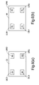
- FIGS. 6( a ) and 6 ( b ) schematically illustrate two optical images I 3 and I 4 generated from different lens modules after the first image analysis procedures are performed according to the focus adjustable method described in the second embodiment, respectively;
- FIG. 7 illustrates a comparison table related to the focus adjusting performance of five lens modules before and after focus adjustment.
- FIG. 8 illustrates a focus adjustable method
- FIG. 9 illustrates another focus adjustable method
- FIG. 10 illustrates another focus adjustable method.
- a focus adjustable system for generating an optical image having four corners' focus values is illustrated.
- an external light beam 21 passes through a lens surface 221 of a lens module 22 , and is then projected onto an image sensor 24 equipped in a lens holding jag 23 .
- an optical image I 2 is outputted to a microprocessor 25 .
- the focus values UL 2 , UR 2 , DL 2 and DR 2 of the optical image I 2 at four corners thereof are obtained.
- sustaining elements 231 are protruded from the inner surface of the lens holding jag 23 to define a receptacle 232 between these sustaining elements 231 .
- the lens module 22 is accommodated within the receptacle 232 .
- the operation principle of controlling the sustaining force applied onto the sustaining elements 231 and the structures of the sustaining elements 231 are similar to those described in the art, and are not to be redundantly described herein.
- the sustaining force is controlled in response to a shift control signal S 2 as shown in FIG. 3 or manually controlled by a resilient element (not shown).
- the focus values UL 2 , UR 2 , DL 2 and DR 2 are computed by the microprocessor 25 to obtain a two-dimensional geometric tilt vector T(X,Y), an image diagonal spinor D and an image tetragonal average value M. According to the values T(X,Y), D and M, the tilt angle and the tilt direction of the lens module 22 and the causes of titled phenomenon are precisely realized, thereby further controlling the sustaining element 231 and the tiny shift of the lens module 22 .
- the process for executing an automatic focus adjustable method according to a first preferred embodiment of the present invention is illustrated with reference to the flowchart of FIG. 4 .
- the two-dimensional geometric tilt vector T(X,Y) and the image tetragonal average value M are employed.
- the optical errors are resulted from inherent imaging tolerance of the lens module 12 during fabrication or the assembling tolerance of the stilted lens module 12 or image sensor 14 .
- the actual causes of the optical errors will not be discussed herein.
- an external light beam 21 is allowed to pass through the lens module 22 , thereby generating the optical image I 2 (Step 42 ).
- Step 43 the focus values UL 2 , UR 2 , DL 2 and DR 2 of the optical image I 2 at four corners thereof are obtained.
- the tilt amount and the tilt angle of the lens module 22 are (X 2 +Y 2 ) 1/2 and arctan(Y/X), respectively.
- X [(DR 2 +UR 2 ) ⁇ (UL 2 +DL 2 )]/(4 ⁇ b)
- Y [(UR 2 +UL 2 ) ⁇ (DR 2 +DL 2 )]/(4 ⁇ a).
- the corners' focus values UL 1 , UR 1 , DL 1 and DR 1 of the optical image I 1 shown in FIG. 2( c ) are 50, 45, 30 and 41, respectively.
- the tilt amount and the tilt angle of the lens module 22 are 24.73 and 1.33°, respectively.
- Step 45 according to the two-dimensional geometric tilt vector T(X,Y), a shift control signal S 2 is automatically issued from the microprocessor 25 for controlling the sustaining force applied on the sustaining elements 231 . Therefore, the position of the lens module 22 in the receptacle 232 is precisely adjusted to achieve a more uniform focusing effect of the lens module 22 .
- the microprocessor 25 may discriminate whether the focus value distribution of the optical image I 2 is optimized after the focus adjustment (Step 47 ). Meanwhile, the focus adjustable method is completed (Step 48 ).
- an external light beam 21 is allowed to pass through the lens module 22 , thereby generating the optical image I 2 (Step 52 ).
- Step 53 the focus values UL 2 , UR 2 , DL 2 and DR 2 of the optical image I 2 at four corners thereof are obtained.
- the tilt amount and the tilt angle of the lens module 22 are (X 2 +Y 2 ) 1/2 and arctan(Y/X), respectively.
- X [(DR 2 +UR 2 ) ⁇ (UL 2 +DL 2 )]/(4 ⁇ b)
- Y [(UR 2 +UL 2 ) ⁇ (DR 2 +DL 2 )]/(4 ⁇ a).
- Step 55 a shift control signal S 2 is automatically issued from the microprocessor 25 for controlling the sustaining force applied on the sustaining elements 231 . Therefore, the position of the lens module 22 in the receptacle 232 is precisely adjusted to achieve a more uniform focusing effect of the lens module 22 .
- the microprocessor 25 may discriminate whether the focus value distribution of the optical image I 2 is optimized after the focus adjustment (Step 57 ).
- the microprocessor 25 may determine the optical systematic errors of the lens module (Step 59 ). Meanwhile, the focus adjustable method is completed (Step 510 ).
- the focus adjustable method described in the second preferred embodiment of the present invention is capable of correcting the tilt phenomenon of the lens module due to assembling tolerance.
- the focus adjustable method of the second preferred embodiment can further avoid erroneously judging focusing performance of the lens module, as will be described in FIGS. 6( a ) and 6 ( b ).
- FIGS. 6( a ) and 6 ( b ) schematically illustrate two optical images I 3 and I 4 generated from different lens modules after the first image analysis procedures are performed according to the focus adjustable method described in the second embodiment, respectively.
- the second image analysis procedures are performed to obtain image tetragonal average values M of 300 and 280 , respectively. From the image tetragonal average values, the focusing performance of the lens module to generate the optical image I 3 is better than the lens module to generate the optical image I 4 . However, when the four corners' focus values of the optical image I 3 , i.e. (UR 3 , UL 3 , DR 3 , DL 3 ) are compared with the four corners' focus values of the optical image I 4 , i.e. (UR 4 , UL 4 , DR 4 , DL 4 ), it is found that the corners' focus values of the optical image I 3 is not uniformly distributed.
- the lens module to generate the optical image I 3 has optical systematic errors.
- the lens module to generate the optical image I 4 has superior optical performance.
- the focus adjusting performance according to the first or second embodiment of the present invention will be further understood with reference to a comparison table as shown in FIG. 7 .
- the terms L 11 and L 12 used herein indicate the first lens module before focus adjustment and the first lens module after focus adjustment, respectively.
- the terms UL, UR, DR and DL are the four corners' focus values of the designated lens module.
- the values X and Y and the image tetragonal average value M are calculated according to the related formulas described in the first or second embodiments of the present invention.
- the term V 11 indicates a difference between the image tetragonal average value M after focus adjustment and the image tetragonal average value M before focus adjustment for the designated lens module.
- the term V 12 is the percentage of the difference.
- L 21 and L 22 used herein indicate the second lens module before focus adjustment and the second lens module after focus adjustment, respectively.
- the rest (L 31 , L 32 ), (L 41 , L 42 ) and (L 51 , L 52 ) may be deduced by analogy.
- the second lens module for example.
- the four corners' focus values of the optical image before focus adjustment are 54, 67, 22 and 50, respectively.
- the values X and Y calculated by the microprocessor 25 (as shown in FIG. 3 ) after the first image analysis procedure are ⁇ 3.9 and 2.3, respectively.
- the tilt amount and tilt direction of the second lens module will be realized.
- the image tetragonal average value M for the second lens module is 48.5.
- the microprocessor 25 may determine whether the focus adjustment is required. In order to perform the focus adjustment, according to the tilt amount and the tilt direction, a shift control signal S 2 is automatically issued from the microprocessor 25 for controlling the sustaining force applied on the sustaining elements 231 . Therefore, the position of the lens module 22 in the receptacle 232 is precisely adjusted to achieve a more uniform focusing effect of the lens module 22 .
- the values X and Y calculated by the microprocessor 25 are ⁇ 9.1 and ⁇ 0.3, respectively.
- the image tetragonal average value M for the second lens module is 61.7.
- the difference V 11 and the difference percentage V 12 for the second lens module are 13.21 and 27.27%, respectively. It is found that the focus values of the optical image for the second lens module after focus adjustment are more uniformly distributed and the image tetragonal average value M is changed from 48.5 to 61.6. Accordingly, the focusing performance of the second lens module is improved after the focus adjustment.
- the four corners' focus values of the optical image are 66, 69, 68 and 66, respectively. Since these focus values are uniformly distributed and the image tetragonal average value M reaches an acceptable value, i.e. 67.2, the microprocessor 25 may discriminate that no focus adjustment is required.
- FIG. 8 illustrates a focus adjustable method 800 .
- the method 800 includes allowing 802 an external light beam to pass through a lens module, thereby generating an optical image.
- the method 800 also includes obtaining 804 focus values UR, UL, DR and DL of said optical image at four corners thereof respectively.
- the method 800 also includes determining 808 optical systematic errors of said lens module according to said image diagonal spinor D.
- the method 800 also includes correcting 812 the tilt phenomenon of said lens module according to said two-dimensional geometric tilt vector T(X,Y) so as to achieve a more uniform focusing effect of said optical image.
- the method 800 also includes discriminating 816 whether the focus value distribution of said optical image is optimized according to said image tetragonal average value M.
- FIG. 9 illustrates another focus adjustable method 900 .
- the method 900 includes allowing 902 an external light beam to pass through a lens module, thereby generating an optical image.
- the method 900 also includes obtaining 904 focus values UR, UL, DR and DL of said optical image at four corners thereof respectively.
- the method 900 also includes discriminating 908 whether the focus value distribution of said optical image is optimized according to said image tetragonal average value M.
- the method 900 also includes correcting 912 the tilt phenomenon of said lens module according to said two-dimensional geometric tilt vector T(X,Y) so as to achieve a more uniform focusing effect of said optical image.
- the method 900 also includes determining 916 optical systematic errors of said lens module according to said image diagonal spinor D.
- FIG. 10 illustrates another focus adjustable method 1000 .
- the method 1000 maybe performed by the microprocessor 15 .
- the method 1000 includes calculating 1002 focus values UR, UL, DR and DL of said optical image at four corners respectively of the image.
- the method 1000 also includes correcting 1006 the tilt phenomenon of said lens module by controlling the sustaining force applied onto the sustaining elements according to said two-dimensional geometric tilt vector T(X,Y) so as to achieve a more uniform focusing effect of said optical image.
- the method 1000 also includes determining 1010 optical systematic errors of said lens module according to said image diagonal spinor D.
- the method 1000 also includes discriminating 1014 whether the focus value distribution of said optical image is optimized according to said image tetragonal average value M.
- the focus adjustable method of the present invention is advantageous for facilitating a user to perform multi-dimensional focus adjustment, realize the actual causes of the optical focusing errors and evaluate the focusing performance of the lens module.
Abstract
A focus adjustable method of an optical image is implemented by a numerical analysis. An external light beam is allowed to pass through a lens module, thereby generating an optical image. The focus values of the optical image at four corners thereof are computed according to specified formulas to obtain a two-dimensional geometric tilt vector T(X,Y), an image diagonal spinor D and an image tetragonal average value M. According to the values T(X,Y), D and M, the tilt amount and the tilt direction of the lens module are adjusted, the optical quality of the lens module is discriminated and the focus value distribution of the lens module is determined.
Description
The present invention relates to a focus adjustable method of an optical image, and more particularly to an automatic focus adjustable method of an optical image by performing a numerical analysis on the focus values at four corners of the optical image.
Currently, an optical lens module is widely used in an electronic product such as a videophone or a mobile phone's camera. In order to adjust, calibrate or detect the focusing operations of the optical lens module, the workers may manually rotate the optical lens module, which is engaged with a lens holding jag having an image sensor therein, to have the lens module rotate up and down along the lens' axis.
Referring to FIG. 1 , a conventional focus adjustable system for generating an optical image having four corners' focus values is illustrated. In the focus adjustable system 10 of FIG. 1 , an external light beam 11 passes through a lens surface 121 of a lens module 12, and is then projected onto an image sensor 14 equipped in a lens holding jag 13. After the light beam is imaged on the image sensor 14, an optical image I1 is outputted to a microprocessor 15. By a so-called full screen algorithm or a modulation transfer function (MTF) algorithm, the focus values UL1, UR1, DL1 and DR1 of the optical image I1 at four corners thereof are obtained. The external surface of the lens module 12 has a first engaging element (e.g. a screw thread) matching with the second engaging element 131 (e.g. a screw channel) on the inner surface of the lens holding jag 13, so that the lens module 12 may be rotated along the inner surface of the lens holding jag 13 forwardly or backwardly. As known, the first and second engaging elements may have any complementary structures as long as they match with each other, and are not to be redundantly described herein.
Referring to FIGS. 2( a) and 2(b), four original corners' focus values before the focus adjustment and four adjusted corners' focus values after the focus adjustment are respectively shown. In FIG. 2( a), the original focus values UL1, UR1, DL1 and DR1 before the focus adjustment are 45, 45, 45 and 45, respectively. In general, the focusing performance is proportioned to the focus value. That is to say, a lower focus value, e.g. 45, indicates the undesirable focusing performance. In order to the adjust the focus values, the worker may manually rotate the lens module 12, which is engaged with the lens holding jag 13, along the X-axis direction, i.e. the lens axis direction. After the focus values UL1, UR1, DL1 and DR1 are increased and reach acceptable values as shown in FIG. 2( b), e.g. 55 or above, the focusing performance of the lens module 12 is improved.
Unfortunately, during the focus adjusting process, the lens module 12 and/or the image sensor 14 is readily tilted. Under this circumstance, the optical path between the lens module 12 and the image sensor 14 will also be tilted. As shown in FIG. 2( c), due to this tilt phenomenon, the focus values UL1, UR1, DL1 and DR1 are changed to for example 50, 45, 30 and 41, respectively, which are not evenly distributed. Since these focus values are not evenly distributed, even if the worker manually rotates the lens module 12 along the X-axis direction, the adjusted focus values are still unevenly distributed. As known, this unsuccessful focusing adjustment may be caused by a fact that the lens holding jag 13 can move only along the X-axis direction. Moreover, since the tilt amount and the tilt angle are not clearly realized according to the prior art, the problem of generating uneven focus values is hard to be overcome.
In addition to the undesired tilted lens module 12 or image sensor 14, the inherent imaging tolerance of the lens module 12 during fabrication also contributes to a tilted optical path. The conventional focus adjustable method fails to discriminate whether the inherent imaging tolerance influences the focusing performance. Furthermore, the conventional focus adjustable method fails to evaluate the overall focusing performance after the lens module 12 is adjusted.
In views of the above-described disadvantages, the applicant keeps on carving unflaggingly to develop an improved focus adjustable method according to the present invention through wholehearted experience and research.
It is an object of the present invention to provide a focus adjustable method of an optical image according to the tilt amount and the tilt direction of the lens module to perform two-dimensional focusing adjustment, so that the focusing performance of the optical image is enhanced.
Another object of the present invention provides a focus adjustable method of an optical image for discriminating the actual cause of the focusing errors.
A still object of the present invention provides a focus adjustable method of an optical image, which is capable evaluating the focusing performance.
In accordance with a first aspect of the present invention, there is provided a focus adjustable method comprising steps of allowing an external light beam to pass through a lens module, thereby generating an optical image; obtaining focus values UR, UL, DR and DL of the optical image at four corners thereof; performing a first image analysis procedure to obtain a two-dimensional geometric tilt vector T(X,Y) according to the formula: T(X,Y)=(X2+Y2)1/2, ∠ arctan(Y/X), where X=[(DR+UR)−(UL+DL)]/b, Y=[(UR+UL)−(DR+DL)]/a, and a and b are correction factors for correcting the aspect ratio; and correcting the tilt phenomenon of the lens module according to the two-dimensional geometric tilt vector T(X,Y) so as to achieve a more uniform focusing effect of the optical image.
Preferably, a=3 and b=4, or a=4 and b=3.
In an embodiment, the focus adjustable method further comprises steps of performing a second image analysis procedure to obtain an image diagonal spinor D according to the formula: D=(DR+UL)−(UR+DL); and determining optical systematic errors of the lens module according to the image diagonal spinor D.
In an embodiment, the focus adjustable method further comprises steps of performing a third image analysis procedure to obtain an image tetragonal average value M according to the formula: M=(DR+UL+UR+DL); and discriminating whether the focus value distribution of the optical image is optimized after the focus adjustment according to the image tetragonal average value M.
Preferably, X=[(DR+UR)−(UL+DL)]/(4×b), Y=[(UR+UL)−(DR+DL)]/(4×a), M=(DR+UL+UR+DL)/4 or D=(DR+UL)−(UR+DL)/4.
In accordance with a second aspect of the present invention, there is provided a focus adjustable method comprising steps of allowing an external light beam to pass through a lens module, thereby generating an optical image; obtaining focus values UR, UL, DR and DL of the optical image at four corners thereof; performing a first image analysis procedure to obtain an image diagonal spinor D according to the formula: D=(DR+UL)−(UR+DL); and determining optical systematic errors of the lens module according to the image diagonal spinor D.
In an embodiment, the focus adjustable method further comprises steps of performing a second image analysis procedure to obtain a two-dimensional geometric tilt vector T(X,Y) according to the formula: T(X,Y)=(X2+Y2)1/2, ∠arctan(Y/X), where X=[(DR+UR)−(UL+DL)]/b, Y=[(UR+UL)−(DR+DL)]/a, and a and b are correction factors for correcting the aspect ratio; and correcting the tilt phenomenon of the lens module according to the two-dimensional geometric tilt vector T(X,Y) so as to achieve a more uniform focusing effect of the optical image.
In an embodiment, the focus adjustable method further comprises steps of performing a third image analysis procedure to obtain an image tetragonal average value M according to the formula: M=(DR+UL+UR+DL); and discriminating whether the focus value distribution of the optical image is optimized after the focus adjustment according to the image tetragonal average value M.
In accordance with a third aspect of the present invention, there is provided a focus adjustable method, comprising steps of allowing an external light beam to pass through a lens module, thereby generating an optical image; obtaining focus values UR, UL, DR and DL of the optical image at four corners thereof; performing a first image analysis procedure to obtain an image tetragonal average value M according to the formula: M=(DR+UL+UR+DL); and discriminating whether the focus value distribution of the optical image is optimized after the focus adjustment according to the image tetragonal average value M.
In an embodiment, the focus adjustable method further comprises steps of performing a second image analysis procedure to obtain a two-dimensional geometric tilt vector T(X,Y) according to the formula: T(X,Y)=(X2+Y2)1/2, ∠ arctan(Y/X), where X=[(DR+UR)−(UL+DL)]/b, Y=[(UR+UL)−(DR+DL)]/a, and a and b are correction factors for correcting the aspect ratio; and correcting the tilt phenomenon of the lens module according to the two-dimensional geometric tilt vector T(X,Y) so as to achieve a more uniform focusing effect of the optical image.
In an embodiment, the focus adjustable method further comprises steps of performing a third image analysis procedure to obtain an image tetragonal average value M according to the formula: M=(DR+UL+UR+DL); and discriminating whether the focus value distribution of the optical image after the focus adjustment is optimized according to the image tetragonal average value M.
The above objects and advantages of the present invention will become more readily apparent to those ordinarily skilled in the art after reviewing the following detailed description and accompanying drawings, in which:
The present invention will now be described more specifically with reference to the following embodiments. It is to be noted that the following descriptions of preferred embodiments of this invention are presented herein for purpose of illustration and description only. It is not intended to be exhaustive or to be limited to the precise form disclosed.
Referring to FIG. 3 , a focus adjustable system for generating an optical image having four corners' focus values according to the present invention is illustrated. In the focus adjustable system 20 of FIG. 3 , an external light beam 21 passes through a lens surface 221 of a lens module 22, and is then projected onto an image sensor 24 equipped in a lens holding jag 23. After the light beam is imaged on the image sensor 24, an optical image I2 is outputted to a microprocessor 25. By a so-called full screen algorithm or a modulation transfer function (MTF) algorithm, the focus values UL2, UR2, DL2 and DR2 of the optical image I2 at four corners thereof are obtained. Several sustaining elements 231 are protruded from the inner surface of the lens holding jag 23 to define a receptacle 232 between these sustaining elements 231. The lens module 22 is accommodated within the receptacle 232. By controlling the sustaining force applied onto the sustaining elements 231, a tiny shift of the lens module 22 in two dimensions is achievable. The operation principle of controlling the sustaining force applied onto the sustaining elements 231 and the structures of the sustaining elements 231 are similar to those described in the art, and are not to be redundantly described herein. For example, the sustaining force is controlled in response to a shift control signal S2 as shown in FIG. 3 or manually controlled by a resilient element (not shown).
According to present invention, the focus values UL2, UR2, DL2 and DR2 are computed by the microprocessor 25 to obtain a two-dimensional geometric tilt vector T(X,Y), an image diagonal spinor D and an image tetragonal average value M. According to the values T(X,Y), D and M, the tilt angle and the tilt direction of the lens module 22 and the causes of titled phenomenon are precisely realized, thereby further controlling the sustaining element 231 and the tiny shift of the lens module 22.
Hereinafter, the process for executing an automatic focus adjustable method according to a first preferred embodiment of the present invention is illustrated with reference to the flowchart of FIG. 4 . In this embodiment, the two-dimensional geometric tilt vector T(X,Y) and the image tetragonal average value M are employed. As previously described, the optical errors are resulted from inherent imaging tolerance of the lens module 12 during fabrication or the assembling tolerance of the stilted lens module 12 or image sensor 14. In this embodiment, the actual causes of the optical errors will not be discussed herein.
After the starting step (Step 41), an external light beam 21 is allowed to pass through the lens module 22, thereby generating the optical image I2 (Step 42).
In Step 43, the focus values UL2, UR2, DL2 and DR2 of the optical image I2 at four corners thereof are obtained.
Then, in Step 44, a first image analysis procedure is performed to obtain a two-dimensional geometric tilt vector T(X,Y) according to the formula: T(X,Y)=(X2+Y2)1/2, ∠ arctan(Y/X), where X=[(DR2+UR2)−(UL2+DL2)]/b, Y=[(UR2+UL2)−(DR2+DL2)]/a, and a and b are correction factors for correcting the aspect ratio. According to the above formula related to the two-dimensional geometric tilt vector T(X,Y), the tilt amount and the tilt angle of the lens module 22 are (X2+Y2)1/2 and arctan(Y/X), respectively. These data are helpful for providing even focus values upon the further automatic adjustment of the lens module 22. Preferably, a=3 and b=4, or a=4 and b=3. Especially, X=[(DR2+UR2)−(UL2+DL2)]/(4×b), and Y=[(UR2+UL2)−(DR2+DL2)]/(4×a).
For example, as previously described, the corners' focus values UL1, UR1, DL1 and DR1 of the optical image I1 shown in FIG. 2( c) are 50, 45, 30 and 41, respectively. According to the above formula described in Step 44, where a=b=1, the values X=6 and Y=1.5 are obtained. In addition, the tilt amount and the tilt angle of the lens module 22 are 24.73 and 1.33°, respectively.
In Step 45, according to the two-dimensional geometric tilt vector T(X,Y), a shift control signal S2 is automatically issued from the microprocessor 25 for controlling the sustaining force applied on the sustaining elements 231. Therefore, the position of the lens module 22 in the receptacle 232 is precisely adjusted to achieve a more uniform focusing effect of the lens module 22.
Then, in Step 46, a second image analysis procedure is performed to obtain an image tetragonal average value M according to the formula: M=(DR2+UL2+UR2+DL2), or especially M=(DR2+UL2+UR2+DL2)/4.
According to the image tetragonal average value M, the microprocessor 25 may discriminate whether the focus value distribution of the optical image I2 is optimized after the focus adjustment (Step 47). Meanwhile, the focus adjustable method is completed (Step 48).
Hereinafter, the process for executing an automatic focus adjustable method according to a second preferred embodiment of the present invention is illustrated with reference to the flowchart of FIGS. 5( a) and 5(b). In this embodiment, the actual causes of the optical errors can be automatically identified.
After the starting step (Step 51), an external light beam 21 is allowed to pass through the lens module 22, thereby generating the optical image I2 (Step 52).
In Step 53, the focus values UL2, UR2, DL2 and DR2 of the optical image I2 at four corners thereof are obtained.
Then, in Step 54, a first image analysis procedure is performed to obtain a two-dimensional geometric tilt vector T(X,Y) according to the formula: T(X,Y)=(X2+Y2)1/2, ∠arctan(Y/X), where X=[(DR2+UR2)−(UL2+DL2)]/b, Y=[(UR2+UL2)−(DR2+DL2)]/a, and a and b are correction factors for correcting the aspect ratio. According to the above formula related to the two-dimensional geometric tilt vector T(X,Y), the tilt amount and the tilt angle of the lens module 22 are (X2+Y2)1/2 and arctan(Y/X), respectively. These data are helpful for providing even focus values upon the further automatic adjustment of the lens module 22. Preferably, a=3 and b=4, or a=4 and b=3. Especially, X=[(DR2+UR2)−(UL2+DL2)]/(4×b), and Y=[(UR2+UL2)−(DR2+DL2)]/(4×a).
In Step 55, a shift control signal S2 is automatically issued from the microprocessor 25 for controlling the sustaining force applied on the sustaining elements 231. Therefore, the position of the lens module 22 in the receptacle 232 is precisely adjusted to achieve a more uniform focusing effect of the lens module 22.
Then, in Step 56, a second image analysis procedure is performed to obtain an image tetragonal average value M according to the formula: M=(DR2+UL2+UR2+DL2), or especially M=(DR2+UL2+UR2+DL2)/4.
According to the image tetragonal average value M, the microprocessor 25 may discriminate whether the focus value distribution of the optical image I2 is optimized after the focus adjustment (Step 57).
Then, in Step 58, a third image analysis procedure is performed to obtain an image diagonal spinor D according to the formula: D=(DR2+UL2)−(UR2+DL2), or especially D=(DR2+UL2)−(UR2+DL2)/4.
According to the image diagonal spinor D, the microprocessor 25 may determine the optical systematic errors of the lens module (Step 59). Meanwhile, the focus adjustable method is completed (Step 510).
The focus adjustable method described in the second preferred embodiment of the present invention is capable of correcting the tilt phenomenon of the lens module due to assembling tolerance. In addition, the focus adjustable method of the second preferred embodiment can further avoid erroneously judging focusing performance of the lens module, as will be described in FIGS. 6( a) and 6(b).
For the optical image I3 and I4, the second image analysis procedures are performed to obtain image tetragonal average values M of 300 and 280, respectively. From the image tetragonal average values, the focusing performance of the lens module to generate the optical image I3 is better than the lens module to generate the optical image I4. However, when the four corners' focus values of the optical image I3, i.e. (UR3, UL3, DR3, DL3) are compared with the four corners' focus values of the optical image I4, i.e. (UR4, UL4, DR4, DL4), it is found that the corners' focus values of the optical image I3 is not uniformly distributed. Therefore, after the second image analysis procedures are performed on the optical images I3 and I4 as described in the second embodiment of the present invention, the variance resulted from the uneven focus values is readily observed. In other words, the lens module to generate the optical image I3 has optical systematic errors. Whereas, the lens module to generate the optical image I4 has superior optical performance.
The focus adjusting performance according to the first or second embodiment of the present invention will be further understood with reference to a comparison table as shown in FIG. 7 .
In the table of FIG. 7 , five lens modules are used to implement the focus adjustable tests. The terms L11 and L12 used herein indicate the first lens module before focus adjustment and the first lens module after focus adjustment, respectively. The terms UL, UR, DR and DL are the four corners' focus values of the designated lens module. The values X and Y and the image tetragonal average value M are calculated according to the related formulas described in the first or second embodiments of the present invention. The term V11 indicates a difference between the image tetragonal average value M after focus adjustment and the image tetragonal average value M before focus adjustment for the designated lens module. Whereas, the term V12 is the percentage of the difference. Likewise, the terms L21 and L22 used herein indicate the second lens module before focus adjustment and the second lens module after focus adjustment, respectively. The rest (L31, L32), (L41, L42) and (L51, L52) may be deduced by analogy.
For example the second lens module for example. The four corners' focus values of the optical image before focus adjustment are 54, 67, 22 and 50, respectively. According to the above formula as described in the first or second embodiment, the values X and Y calculated by the microprocessor 25 (as shown in FIG. 3 ) after the first image analysis procedure are −3.9 and 2.3, respectively. Moreover, according to the values X and Y, the tilt amount and tilt direction of the second lens module will be realized. After the second image analysis procedure as described in the first or second embodiment, the image tetragonal average value M for the second lens module is 48.5.
According to the related values, e.g. the four corners' focus values, the calculated tilt amount and tilt direction, the microprocessor 25 may determine whether the focus adjustment is required. In order to perform the focus adjustment, according to the tilt amount and the tilt direction, a shift control signal S2 is automatically issued from the microprocessor 25 for controlling the sustaining force applied on the sustaining elements 231. Therefore, the position of the lens module 22 in the receptacle 232 is precisely adjusted to achieve a more uniform focusing effect of the lens module 22.
In another case that the second lens module is used and the four corners' focus values of the optical image are 71, 51, 54 and 70, respectively, the values X and Y calculated by the microprocessor 25 are −9.1 and −0.3, respectively. After the second image analysis procedure, the image tetragonal average value M for the second lens module is 61.7. The difference V11 and the difference percentage V12 for the second lens module are 13.21 and 27.27%, respectively. It is found that the focus values of the optical image for the second lens module after focus adjustment are more uniformly distributed and the image tetragonal average value M is changed from 48.5 to 61.6. Accordingly, the focusing performance of the second lens module is improved after the focus adjustment.
For the fifth lens module, the four corners' focus values of the optical image are 66, 69, 68 and 66, respectively. Since these focus values are uniformly distributed and the image tetragonal average value M reaches an acceptable value, i.e. 67.2, the microprocessor 25 may discriminate that no focus adjustment is required.
From the above description, the focus adjustable method of the present invention is advantageous for facilitating a user to perform multi-dimensional focus adjustment, realize the actual causes of the optical focusing errors and evaluate the focusing performance of the lens module.
While the invention has been described in terms of what is presently considered to be the most practical and preferred embodiments, it is to be understood that the invention needs not be limited to the disclosed embodiment. On the contrary, it is intended to cover various modifications and similar arrangements included within the spirit and scope of the appended claims which are to be accorded with the broadest interpretation so as to encompass all such modifications and similar structures.
Claims (10)
1. A focus adjustable method, comprising steps of:
allowing an external light beam to pass through a lens module, thereby generating an optical image;
obtaining focus values UR, UL, DR and DL of said optical image at four corners thereof respectively;
performing a first image analysis procedure to obtain an image diagonal spinor D according to one of the formulas: D=(DR+UL)−(UR+DL) or D=(DR+UL)−(UR+DL)/4;
determining optical systematic errors of said lens module according to said image diagonal spinor D;
performing a second image analysis procedure to obtain a two-dimensional geometric tilt vector T(X,Y) according to the formulas: T(X,Y)=(X2+Y2)1/2, ∠ arctan(Y/X), where X=[(DR+UR)−(UL+DL)]/b, Y=[(UR+UL)−(DR+DL)]/a, or X=[(DR+UR)(UL+DL)]/(4×b), Y=[(UR+UL)−(DR+DL)]/(4×a), and a and b are correction factors for correcting an aspect ratio of said lens module; and
correcting a tilt phenomenon of said lens module according to said two-dimensional geometric tilt vector T(X,Y) so as to achieve a more uniform focusing effect of said optical image.
2. The focus adjustable method according to claim 1 wherein a=3 and b=4, or a=4 and b=3.
3. The focus adjustable method according to claim 1 further comprising steps of:
performing a third image analysis procedure to obtain an image tetragonal average value M according to one of the formulas: M=(DR+UL+UR+DL), or M=(DR+UL+UR+DL)/4 or M=(DR+UL)−(UR+DL)/4; and
discriminating whether a focus value distribution of said optical image is optimized according to said image tetragonal average value M.
4. A focus adjustable method, comprising steps of:
allowing an external light beam to pass through a lens module, thereby generating an optical image;
obtaining focus values UR, UL, DR and DL of said optical image at four corners thereof respectively;
performing a first image analysis procedure to obtain an image tetragonal average value M according to one of the formulas: M=(DR+UL+UR+DL) or M=(DR+UL+UR+DL)/4;
discriminating whether a focus value distribution of said optical image is optimized according to said image tetragonal average value M;
performing a second image analysis procedure to obtain a two-dimensional geometric tilt vector T(X,Y) according to the formulas: T(X,Y)=(X2+Y2)1/2, ∠ arctan(Y/X), where X=[(DR+UR)−(UL+DL)]/b, Y=[(UR+UL)−(DR+DL)]/a, or X=[(DR+UR)(UL+DL)]/(4×b), Y=[(UR+UL)−(DR+DL)]/(4×a), and a and b are correction factors for correcting an aspect ratio of said lens module; and
correcting a tilt phenomenon of said lens module according to said two-dimensional geometric tilt vector T(X,Y) so as to achieve a more uniform focusing effect of said optical image.
5. The focus adjustable method according to claim 4 wherein a=3 and b=4, or a=4 and b=3.
6. The focus adjustable method according to claim 4 further comprising steps of:
performing a third image analysis procedure to obtain an image diagonal spinor D according to one of the formulas: D=(DR+UL)−(UR+DL) or D=(DR+UL)−(UR+DL)/4; and
determining optical systematic errors of said lens module according to said image diagonal spinor D.
7. A focus adjustable system, for adjusting the focus of an optical lens module, comprising:
a light source, for generating a light beam;
a lens holding jag, having a receptacle for installing the optical lens module therein, the lens holding jag also having plural sustaining elements and an image sensor, wherein the lens module is sustained by the sustaining elements and the light beam is passed through the lens module and projected on the image sensor to generate an optical image;
a microprocessor connecting to the lend holding jag, for
calculating focus values UR, UL, DR and DL of said optical image at four corners respectively of the image,
performing a first image analysis procedure to obtain a two-dimensional geometric tilt vector T(X,Y) according to the formulas: T(X,Y)=(X2+Y2)1/2, ∠ arctan(Y/X), where X=[(DR+UR)−(UL+DL)]/b, Y=[(UR+UL)−(DR+DL)]/a, or X=[(DR+UR)−(UL+DL)]/(4×b), Y=[(UR+UL)−(DR+DL)]/(4×a) and a and b are correction factors for correcting an aspect ratio of the lens module, and
correcting a tilt phenomenon of said lens module by controlling the sustaining force applied onto the sustaining elements according to said two-dimensional geometric tilt vector T(X,Y) so as to achieve a more uniform focusing effect of said optical image.
8. The focus adjustable system according to claim 7 , wherein a=3 and b=4, or a=4 and b=3.
9. The focus adjustable system according to claim 8 , wherein the microprocessor is also configured to:
perform a second image analysis procedure to obtain an image diagonal spinor D according to one of the formulas: D=(DR+UL)−(UR+DL) or D=(DR+UL)−(UR+DL)/4; and
determine optical systematic errors of said lens module according to said image diagonal spinor D.
10. The focus adjustable system according to claim 9 , wherein the microprocessor is also configured to:
perform a third image analysis procedure to obtain an image tetragonal average value M according to one of the formulas: M=(DR+UL+UR+DL) or M=(DR+UL+UR+DL)/4; and
discriminate whether a focus value distribution of said optical image is optimized according to said image tetragonal average value M.
Applications Claiming Priority (2)
| Application Number | Priority Date | Filing Date | Title |
|---|---|---|---|
| TW094133456 | 2005-09-27 | ||
| TW094133456A TWI291592B (en) | 2005-09-27 | 2005-09-27 | Adjusting method for focus of optical image |
Publications (2)
| Publication Number | Publication Date |
|---|---|
| US20070071349A1 US20070071349A1 (en) | 2007-03-29 |
| US7634183B2 true US7634183B2 (en) | 2009-12-15 |
Family
ID=37894047
Family Applications (1)
| Application Number | Title | Priority Date | Filing Date |
|---|---|---|---|
| US11/271,363 Expired - Fee Related US7634183B2 (en) | 2005-09-27 | 2005-11-10 | Focus adjustable method of optical image |
Country Status (2)
| Country | Link |
|---|---|
| US (1) | US7634183B2 (en) |
| TW (1) | TWI291592B (en) |
Cited By (2)
| Publication number | Priority date | Publication date | Assignee | Title |
|---|---|---|---|---|
| US20110157390A1 (en) * | 2009-12-25 | 2011-06-30 | Hong Fu Jin Precision Industry (Shenzhen) Co., Ltd. | Method and system for measuring lens quality |
| US8731388B1 (en) * | 2012-12-21 | 2014-05-20 | Larview Technologies Corporation | Method for automatically focusing applied to camera module |
Families Citing this family (2)
| Publication number | Priority date | Publication date | Assignee | Title |
|---|---|---|---|---|
| US20070133969A1 (en) * | 2005-12-12 | 2007-06-14 | Ess Technology, Inc. | System and method for measuring and setting the focus of a camera assembly |
| CN103048766B (en) * | 2013-01-24 | 2015-07-22 | 华为技术有限公司 | Automatic focusing method and automatic focusing device |
Citations (3)
| Publication number | Priority date | Publication date | Assignee | Title |
|---|---|---|---|---|
| US4782474A (en) * | 1985-01-31 | 1988-11-01 | Fujitsu Limited | Tracking servo system for controllably projecting an optical beam on an optical disk |
| US5691765A (en) * | 1995-07-27 | 1997-11-25 | Sensormatic Electronics Corporation | Image forming and processing device and method for use with no moving parts camera |
| US20050058030A1 (en) * | 2003-09-12 | 2005-03-17 | Hanks Darwin Mitchel | Optical disk drive focusing apparatus |
-
2005
- 2005-09-27 TW TW094133456A patent/TWI291592B/en not_active IP Right Cessation
- 2005-11-10 US US11/271,363 patent/US7634183B2/en not_active Expired - Fee Related
Patent Citations (3)
| Publication number | Priority date | Publication date | Assignee | Title |
|---|---|---|---|---|
| US4782474A (en) * | 1985-01-31 | 1988-11-01 | Fujitsu Limited | Tracking servo system for controllably projecting an optical beam on an optical disk |
| US5691765A (en) * | 1995-07-27 | 1997-11-25 | Sensormatic Electronics Corporation | Image forming and processing device and method for use with no moving parts camera |
| US20050058030A1 (en) * | 2003-09-12 | 2005-03-17 | Hanks Darwin Mitchel | Optical disk drive focusing apparatus |
Cited By (3)
| Publication number | Priority date | Publication date | Assignee | Title |
|---|---|---|---|---|
| US20110157390A1 (en) * | 2009-12-25 | 2011-06-30 | Hong Fu Jin Precision Industry (Shenzhen) Co., Ltd. | Method and system for measuring lens quality |
| US8644634B2 (en) * | 2009-12-25 | 2014-02-04 | Hong Fu Jin Precision Industry (Shenzhen) Co., Ltd. | Method and system for measuring lens quality |
| US8731388B1 (en) * | 2012-12-21 | 2014-05-20 | Larview Technologies Corporation | Method for automatically focusing applied to camera module |
Also Published As
| Publication number | Publication date |
|---|---|
| TWI291592B (en) | 2007-12-21 |
| TW200712722A (en) | 2007-04-01 |
| US20070071349A1 (en) | 2007-03-29 |
Similar Documents
| Publication | Publication Date | Title |
|---|---|---|
| US7469097B2 (en) | Method and apparatus for coping with condition in which subject is too close to digital imaging device for acceptable focus | |
| US7175285B2 (en) | Projection system that adjusts for keystoning | |
| EP2677754B1 (en) | Projector, trapezoidal distortion correction method, carrier medium storing trapezoidal distortion correction program, and trapezoidal distortion correction program | |
| US7986875B2 (en) | Sound-based focus system and focus method thereof | |
| US10021307B2 (en) | Processing apparatus for camera shake correction | |
| US7144115B2 (en) | Projection system | |
| US20160061594A1 (en) | System and method of measuring and correcting tilt angle of lens | |
| US7609458B2 (en) | Projection apparatus, elevation angle control method therefor and recording medium | |
| US20160173762A1 (en) | Image-capturing apparatus | |
| US20160065833A1 (en) | Image capturing device and auto-focusing method thereof | |
| US11146734B2 (en) | Image capturing apparatus and image monitoring system | |
| US20060221227A1 (en) | Focusing method for image-capturing device | |
| US7634183B2 (en) | Focus adjustable method of optical image | |
| US20140071302A1 (en) | Processing apparatus, processing method, and program | |
| US8526805B2 (en) | Lens apparatus and camera system including the same | |
| KR100781273B1 (en) | Error Compensation Apparatus and Method of Camera Module | |
| JP2019211661A (en) | Zoom lens and image capturing device | |
| US20150281552A1 (en) | Image-capturing apparatus | |
| JP2007166494A (en) | Camera and imaging unit | |
| CN111770329B (en) | Method for correcting position of photosensitive element | |
| JP2009003152A (en) | Focus adjustment device and focus adjustment method for camera module | |
| US11320725B2 (en) | Projection type display apparatus, projection type display system, control method of projection type display apparatus, and storage medium | |
| JP4489130B2 (en) | A tilt correction method and tilt correction apparatus for an imaging apparatus | |
| US10897589B2 (en) | Image pickup apparatus including mechanism for attaching and detaching transparent cover, image processing method thereof, and storage medium | |
| JP7066395B2 (en) | Image pickup device and its control method |
Legal Events
| Date | Code | Title | Description |
|---|---|---|---|
| AS | Assignment |
Owner name: PRIMAX ELECTRONICS LTD., TAIWAN Free format text: ASSIGNMENT OF ASSIGNORS INTEREST;ASSIGNORS:CHIN, HOU-CHING;CHANG, CHIH-CHIEN;REEL/FRAME:017234/0042 Effective date: 20051018 |
|
| CC | Certificate of correction | ||
| FPAY | Fee payment |
Year of fee payment: 4 |
|
| REMI | Maintenance fee reminder mailed | ||
| LAPS | Lapse for failure to pay maintenance fees |
Free format text: PATENT EXPIRED FOR FAILURE TO PAY MAINTENANCE FEES (ORIGINAL EVENT CODE: EXP.) |
|
| STCH | Information on status: patent discontinuation |
Free format text: PATENT EXPIRED DUE TO NONPAYMENT OF MAINTENANCE FEES UNDER 37 CFR 1.362 |
|
| FP | Lapsed due to failure to pay maintenance fee |
Effective date: 20171215 |