US7624549B2 - Wall-ceiling slip joint permitting seismic induced movement - Google Patents
Wall-ceiling slip joint permitting seismic induced movement Download PDFInfo
- Publication number
- US7624549B2 US7624549B2 US11/844,856 US84485607A US7624549B2 US 7624549 B2 US7624549 B2 US 7624549B2 US 84485607 A US84485607 A US 84485607A US 7624549 B2 US7624549 B2 US 7624549B2
- Authority
- US
- United States
- Prior art keywords
- wall
- spacer
- wall panel
- bolt
- guide
- Prior art date
- Legal status (The legal status is an assumption and is not a legal conclusion. Google has not performed a legal analysis and makes no representation as to the accuracy of the status listed.)
- Active, expires
Links
Images


Classifications
-
- E—FIXED CONSTRUCTIONS
- E04—BUILDING
- E04B—GENERAL BUILDING CONSTRUCTIONS; WALLS, e.g. PARTITIONS; ROOFS; FLOORS; CEILINGS; INSULATION OR OTHER PROTECTION OF BUILDINGS
- E04B2/00—Walls, e.g. partitions, for buildings; Wall construction with regard to insulation; Connections specially adapted to walls
- E04B2/74—Removable non-load-bearing partitions; Partitions with a free upper edge
- E04B2/82—Removable non-load-bearing partitions; Partitions with a free upper edge characterised by the manner in which edges are connected to the building; Means therefor; Special details of easily-removable partitions as far as related to the connection with other parts of the building
-
- E—FIXED CONSTRUCTIONS
- E04—BUILDING
- E04B—GENERAL BUILDING CONSTRUCTIONS; WALLS, e.g. PARTITIONS; ROOFS; FLOORS; CEILINGS; INSULATION OR OTHER PROTECTION OF BUILDINGS
- E04B2/00—Walls, e.g. partitions, for buildings; Wall construction with regard to insulation; Connections specially adapted to walls
- E04B2/74—Removable non-load-bearing partitions; Partitions with a free upper edge
- E04B2/7407—Removable non-load-bearing partitions; Partitions with a free upper edge assembled using frames with infill panels or coverings only; made-up of panels and a support structure incorporating posts
- E04B2/7409—Removable non-load-bearing partitions; Partitions with a free upper edge assembled using frames with infill panels or coverings only; made-up of panels and a support structure incorporating posts special measures for sound or thermal insulation, including fire protection
Definitions
- This invention pertains to partition wall systems and, more particularly, to an engagement assembly that couples a wall panel to the ceiling without piercing the ceiling itself.
- the engagement assembly may also provide a sound and light attenuation barrier.
- the present invention is believed to be particularly applicable for wall systems located in areas prone to measurable seismic events.
- interconnected modular wall systems are being used to define offices, conference rooms, storage rooms, and workrooms.
- the wall systems are not designed to be load bearing. As such, they can be fastened to the floor and the suspended ceiling of a building at nearly any location.
- the wall systems can be rearranged or replaced, as needed, without affecting the structural integrity of the building.
- An exemplary modular wall system is the Genius wall system, commercially available from Krueger International, Inc. of Green Bay, Wis.
- New seismic regulations require that a suspended ceiling be able to sway like a pendulum a predetermined distance, e.g. one inch, in all directions in response to a seismic event. This can be particularly problematic for wall panels that are attached, using fasteners or similar connectors, directly to the suspended ceiling. Moreover, code requirements demand that the wall panels be able to withstand the impact of a seismic event. This has led to the design of sturdier wall panels. While having an improved response to seismic events, the seal between the suspending ceiling and the wall panel can be susceptible to sound and/or light transference. This has led to the need for a series of braces above the ceiling (called kicker braces) that support the walls that can be expensive and time consuming to install.
- kicker braces braces above the ceiling
- the kicker braces attach to the top of the wall and to the building structure above the ceiling at 45 degrees every four feet.
- the penetration through the suspended ceiling has to be large enough for the brace plus one inch clearance around the brace to allow the ceiling to sway unobstructed. This penetration can be wider than the width of the wall, which can compromise the effectiveness of the wall system.
- This disclosure is directed to a modular wall system used in a space dividing system, such as an office space configuration system, suitable for seismic active areas.
- the system includes a partition wall or wall panel designed to extend between the floor of the office interior and the ceiling.
- the partition wall is held stationary in this position without any fasteners, braces or other securing members that penetrate into the ceiling.
- the wall includes a pair of wall extensions secured to opposite sides of the wall and that contain a sound attenuating material, such as a foam material or fiberglass therebetween.
- an apparatus for retaining a wall panel to a ceiling surface includes a pair of wall extensions adapted to abut against the ceiling surface and a guide that retains the wall extensions, and which carries a shank.
- the apparatus further includes a spacer coupled to the shank and adapted to snugly retain the wall extensions against the wall panel. The height of the wall panel relative to the spacer is defined by the position of the spacer relative to the shank.
- the present invention is directed to a wall system adapted for use in regions with seismic building criteria.
- the wall system includes a wall panel and a spacer connected to the wall panel.
- the wall system further includes a wall extension member adapted to abut a ceiling and further adapted to adjustably retain the spacer at one of a plurality of heights.
- the present invention is directed to an apparatus for extending the height of a wall panel to traverse a distance between a floor surface supporting the wall panel and a ceiling surface.
- the apparatus includes a pair of wall extensions adapted to snugly fit against respective exterior wall surfaces of the wall panel.
- a guide removably retains the pair of extensions and carries a threaded spacer that threadedly receives a bolt adapted to carry the wall panel.
- the height of the wall extensions relative to the wall panel is set by the position of the bolt on the threaded spacer, such that the extensions can be positioned against the ceiling surface.
- FIG. 1 is a partial isometric view of a modular wall system in which the upper end of the panels of the wall system are adapted to engage the ceiling of a space within a building using the wall panel-ceiling engagement assembly according to the present invention
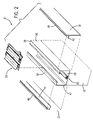
- FIG. 2 is a partial, enlarged exploded isometric view of the wall panel-ceiling engagement assembly incorporated in the modular wall system of FIG. 1 ;
- FIG. 3 is an exploded isometric view of a guide forming a part of the wall panel-ceiling engagement assembly of FIG. 2 ;
- FIG. 4 is a section view of the modular wall system taken along lines 4 - 4 of FIG. 1 ;
- FIG. 5 is a section view similar to that of FIG. 4 showing the wall panel-ceiling engagement assembly being retained at an elevation greater than that shown in FIG. 4 ;
- FIG. 6 is a section view similar to that of FIGS. 4 and 5 showing the wall panel-ceiling engagement device being retained at an elevation greater than shown in both FIGS. 4 and 5 ;
- FIG. 7 is an isometric view of a corner brace used to join adjacent panels.
- FIG. 1 shows a portion of a modular wall system 10 composed of a pair of wall panels (or partition walls) 12 connected to one another by a corner brace 14 .
- a corner cover 15 extends from the corner brace 14 and runs the height of the pair of wall panels 12 and assists in connecting the adjacent wall panels 12 to one another.
- the corner brace 14 allows the joined wall panels to swing as a single structure during seismic events.
- the wall panels 12 are designed to abut the underside of a suspended ceiling (not shown) via a slip joint connection, which will be explained.
- the wall panels 12 are constructed to be shorter than the distance between the suspended ceiling and a floor, shown at 16 .
- each wall panel 12 and the ceiling is traversed by a pair of wall extensions 18 , 20 designed to abut against the underside of the suspended ceiling and be retained thereagainst without the use of a fastener or similar device penetrating through the ceiling.
- a channel 22 is defined between the wall extensions 18 , 20 which, in a preferred embodiment, is filled with light and sound abatement material, such as foam or insulation.
- a wall panel-ceiling engagement device or assembly 24 is retained within the channel 22 and, as will be described, receives the wall extensions 18 , 20 in a manner that allows the height of the wall extensions 18 , 20 relative to the wall panel 12 to be adjusted.
- Wall system 10 may be generally constructed as shown and described in U.S. Pat. No. 6,688,056 granted Feb. 10, 2004, the disclosure of which is hereby incorporated by reference. It is understood, however, that wall system 10 may have any other desired construction.
- each section of wall panel 12 includes an upper frame member 26 .
- the upper frame member 26 has a lower surface 28 interconnected between a pair of sidewalls 30 , 32 having inwardly projecting flanges 34 , 36 , respectively.
- Flanges 34 , 36 are engaged with and received by the wall panel-ceiling engagement device 24 , in a manner to be explained, so as to couple the wall panel 12 to the wall panel-ceiling engagement device 24 .
- sheet metal screws or similar fasteners may be used.
- wall extensions 18 , 20 are designed to abut exteriorly of sidewalls 30 , 32 , respectively, of upper frame member 26 .
- Each wall extension 18 , 20 is constructed to have a lip 38 , 40 , respectively, that is designed to abut against the underside of a ceiling, which representatively may be a suspended ceiling.
- wall extensions 18 , 20 have respective inwardly extending arms 42 , 44 . Arms 42 , 44 are designed to be retained by the wall panel-ceiling engagement device 24 , thereby coupling the wall extensions 18 , 20 to the wall panel-ceiling engagement device 24 .
- wall panel-ceiling engagement device 24 has a guide 46 composed of a pair of top guide plates 48 connected to a bottom guide plate 50 in a manner such that a gap 52 is formed therebetween. Gap 52 forms a receptacle or space for receiving arms 42 , 44 of the wall extensions 18 , 20 .
- a stud or bolt 54 extends downwardly from guide 46 and is constructed to receive a spacer 56 .
- top guide plates 48 and the bottom guide plate 50 are in the form of extruded members formed of a material such as aluminum or steel, although it is understood that any other satisfactory material and forming method may be employed.
- Top guide plates 48 and bottom guide plate 50 include mating connection structure that enables guide plates 48 , 50 to be connected together.
- the mating connection structure may be in the form of a pair of upwardly facing T-connectors 53 formed on lower guide member 50 , each of which is adapted to fit within a respective channel 55 formed on upper guide plates 48 .
- the mating connection structure may be in the form of facing channels formed on lower guide plates, which receive T-shaped connectors formed on the upper guide plate.
- spacer 56 includes a pair of spacer plates 58 , 60 separated from one another by a center plate 62 .
- a grommet 64 has a barrel 66 that extends centrally through plates 58 - 62 , and includes an interior wall 68 having threads that engage threads 70 of the bolt 54 when the spacer 56 is threaded onto bolt 54 or bolt 54 is threaded into grommet 64 . It is contemplated that the spacer 56 may be threaded onto bolt 54 with the grommet 64 facing downward or with the grommet facing upward, with both positions being illustrated in FIG. 3 .
- Center plate 62 is angularly offset from plates 58 , 60 thereby forming a channel between plates 58 , 60 that is adapted to receive flanges 34 , 36 .
- Center plate 62 has a width that matches the distance between the facing edges of flanges 34 , 36 .
- flanges 34 , 36 are received in the channel and abut the lateral edges of center plate 62 .
- screws or rivets 72 fixedly attach flanges 34 , 36 to plates 58 , 60 .
- the wall panel 12 is attached to spacer 56 by upper frame member 26 . It is noted that that wall panel 12 is also fixedly coupled to the upper frame member 26 by a channel and lock assembly 74 , as known in the art. Alternately, spacer 56 may be screwed directly to the upper frame member 26 .
- wall panel-ceiling engagement device 24 further includes a spacing bolt 76 coupled to guide 46 by a retention pin 78 .
- Spacing bolt 76 defines a minimum distance between spacer plate 58 and guide 46 . That is, spacing bolt 76 is operative as a stop for the spacer 56 thereby providing a rotational limitation for the spacer when being threaded to bolt 54 .
- spacing bolt 76 is coupled to a retention rivet 78 . More particularly, the head of the bolt 76 has a clearance hole extending at least partially therethrough. Rivet 78 passes through the clearance hole in aluminum extrusion and into the hole in the head of the bolt 76 . This allows the spacer to be adjusted up and down without spinning around. That is, a user can clip one wall extension onto one side, adjust the bolt until the wall extension makes contact with the ceiling, install noise and/or light abatement material if desired, and clip on the other wall extension knowing that the spacer is properly adjusted.
- Wall extensions 18 , 20 , flanges 34 , 36 , spacer plate 58 , and ceiling 80 collectively form a cavity 82 that, in one preferred embodiment, is filled with sound and light abatement material 84 .
- the sound and light abatement material is insulating foam or fiberglass, but is recognized that other sound and light abatement materials may be used. It is also contemplated that the sound and light abatement materials may also be deposited in the space formed between spacer 56 and the bottom surface 28 of the upper frame member 26 .
- guide 46 is constructed to form a gap 52 adapted to receive arms 42 , 44 of wall extensions 18 , 20 , respectively.
- arms 42 , 44 have rounded ends 86 , 88 , respectively, that rest within grooves 90 , 92 , respectively, formed in the lower guide plate 50 .
- top guide plates 48 exert a downward bias on arms 42 , 44 , that forcibly engage arms 42 , 44 with lower guide plate 50 .
- the arms 42 , 44 and thus the wall extensions 18 , 20 , are securely coupled to guide 46 .
- the top guide plate 48 pressing down on the arms 42 , 44 causes the wall panel-ceiling engagement device 24 to rotate down sealing against the wall panel 12 .
- the height of the wall extensions 18 , 20 relative to the wall panel 12 is determined by the position of spacer 56 on bolt 54 .
- FIGS. 4 and 5 show two possible positions of the wall extensions 18 , 20 relative to the wall panel 12 .
- the wall extensions 18 , 20 are closer to the top of the wall panel 12 than in FIG. 5 .
- the threaded grommet 64 allows the spacer 56 to be retained on the bolt 54 even when the distal end 94 of the bolt 54 does not extend past the grommet 64 , as shown in FIG. 4 .
- spacer 56 may be oriented in two different positions. One position is shown in FIGS. 4-5 whereas the other position is shown in FIG. 6 . In the position shown in FIG. 6 , the barrel 66 of the grommet 64 is rotated 180 degrees from the position shown in FIGS. 4-5 . This allows the distance between the guide 46 and the spacer 56 to be greater than that possible when the spacer is oriented in the manner shown in FIGS. 4-5 . For example, in both FIGS. 5 and 6 , the spacer is retained at the sixth lowest thread 70 of bolt 54 . However, because the spacer 56 has been rotated or inverted in the orientation shown in FIG. 6 , the space between the guide 46 and the spacer 56 is greater than that of FIG. 5 even though the top of the spacer 56 is retained on the sixth lowest thread 70 in FIG. 5 .
- the upper frame member 26 is secured to the wall panel 12 , and the wall panel 12 is then placed in a desired position on the floor 16 such that the upper frame member 26 is located adjacent and below the ceiling, shown at 80 .
- Spacer 56 is then secured to the flanges 34 , 36 using screws 72 . This is followed by coupling the guide 46 to the spacer 56 .
- one of the wall extensions 18 , 20 is snapped into place, as described above.
- Noise and light abatement material 84 such as foam, is then preferably placed into the cavity 82 defined between the ceiling 80 and the spacer 56 .
- the other wall extension 18 , 20 is then snapped into place, thereby securing the noise and light abatement material 84 .
- the wall panel 12 When assembled, the wall panel 12 is retained against the suspended ceiling 80 , without the use of fasteners penetrating ceiling 80 , by the noise and light abatement material and the lips 38 , 40 of the wall extensions 18 , 20 , respectively, in a manner that allows wall panel 12 to slip or sway in accordance with government regulations in response to a seismic event.
- the noise and light abatement material provides insulation against the ingress and egress of noise and light between rooms or spaces, and the variability permitted in retaining the bolt 54 in spacer 56 allows the wall panel 12 to be used in buildings of differing ceiling heights.
- corner brace 14 for connecting a pair of wall panels 12 to one another is shown.
- the corner brace 14 is adapted to connect wall panels 12 that are arranged perpendicular to one another, but it is recognized that the corner brace 14 may be modified to connect wall panels 12 that are inline with one another. Additionally, the corner brace 14 may be modified to connect more than two wall panels to one another.
- corner brace 14 has an L-shaped body 96 that defines a first leg 98 and a second leg 100 that extends along an axis perpendicular to that of the first leg 98 .
- Holes 102 are formed in a spaced arrangement along the body 96 are designed to receive fasteners 104 , FIG. 1 , such as screws, bolts, pins, rivets, and the like, to connect each leg 98 , 100 to a respective wall panel 12 .
- fasteners 104 FIG. 1
- the corner brace 14 functions to join adjacent wall panels 12 such that the wall panels 12 support each other.
- the corner brace 14 functions to keep the wall panels 12 upright notwithstanding swaying of the wall panels 12 themselves.
- the connected wall panels 12 sway as a collective unit.
- the body 96 could be shaped to have more than two legs such that more than two wall panels 12 could be connected using a single brace 14 .
- a three-way brace could be used to connect three panels together and a four-way brace could be used to connect four panels together.
- each of the legs are perpendicular to one another, it is understood that for some applications it would be desirous for the brace to connect wall panels arranged at non-right angles to one another.
Landscapes
- Engineering & Computer Science (AREA)
- Architecture (AREA)
- Physics & Mathematics (AREA)
- Electromagnetism (AREA)
- Civil Engineering (AREA)
- Structural Engineering (AREA)
- Building Environments (AREA)
Abstract
Description
Claims (19)
Priority Applications (3)
| Application Number | Priority Date | Filing Date | Title |
|---|---|---|---|
| US11/844,856 US7624549B2 (en) | 2007-08-24 | 2007-08-24 | Wall-ceiling slip joint permitting seismic induced movement |
| MX2008006019A MX2008006019A (en) | 2007-08-24 | 2008-05-08 | Wall-ceiling slip joint permitting seismic induced movement. |
| CA2638262A CA2638262C (en) | 2007-08-24 | 2008-07-23 | Wall ceiling slip joint permitting seismic induced movement |
Applications Claiming Priority (1)
| Application Number | Priority Date | Filing Date | Title |
|---|---|---|---|
| US11/844,856 US7624549B2 (en) | 2007-08-24 | 2007-08-24 | Wall-ceiling slip joint permitting seismic induced movement |
Publications (2)
| Publication Number | Publication Date |
|---|---|
| US20090049766A1 US20090049766A1 (en) | 2009-02-26 |
| US7624549B2 true US7624549B2 (en) | 2009-12-01 |
Family
ID=40380861
Family Applications (1)
| Application Number | Title | Priority Date | Filing Date |
|---|---|---|---|
| US11/844,856 Active 2027-12-29 US7624549B2 (en) | 2007-08-24 | 2007-08-24 | Wall-ceiling slip joint permitting seismic induced movement |
Country Status (3)
| Country | Link |
|---|---|
| US (1) | US7624549B2 (en) |
| CA (1) | CA2638262C (en) |
| MX (1) | MX2008006019A (en) |
Cited By (10)
| Publication number | Priority date | Publication date | Assignee | Title |
|---|---|---|---|---|
| US20090031653A1 (en) * | 2007-08-02 | 2009-02-05 | Nash Alan C | Partition mounting system and clamp assembly for mounting partition |
| US20100095615A1 (en) * | 2008-10-21 | 2010-04-22 | Alain Leo Houle | Ceiling attachment for full-height panel |
| US20100307082A1 (en) * | 2007-08-02 | 2010-12-09 | Nash Alan C | Partition mounting system and clamp assembly for mounting partition |
| US20110232219A1 (en) * | 2010-03-24 | 2011-09-29 | Wilkinson Jr Edgar L | Overhead panel and installation system |
| US8601749B2 (en) | 2010-05-05 | 2013-12-10 | Allsteel, Inc. | Modular wall system |
| US9366382B2 (en) * | 2012-02-14 | 2016-06-14 | Metalglas Bonomi S.R.L. | Regulation and/or locking device for a plate |
| US20180238051A1 (en) * | 2017-02-22 | 2018-08-23 | Jeffrey L. Feltman | Partition Clip |
| US10174501B1 (en) * | 2017-09-06 | 2019-01-08 | Usg Interiors, Llc | Metal baffles |
| CN110777970A (en) * | 2019-11-14 | 2020-02-11 | 江苏科技大学 | Friction energy consumption protection device for wall corner of swinging wall and swinging wall |
| US11459766B2 (en) | 2019-12-05 | 2022-10-04 | R&B Wagner, Inc. | Leveling partition mounting system |
Families Citing this family (6)
| Publication number | Priority date | Publication date | Assignee | Title |
|---|---|---|---|---|
| US7624549B2 (en) * | 2007-08-24 | 2009-12-01 | Krueger International, Inc. | Wall-ceiling slip joint permitting seismic induced movement |
| US8713869B1 (en) * | 2013-03-15 | 2014-05-06 | Gordon Sales, Inc. | Suspended containment wall system |
| US9657509B2 (en) * | 2014-01-30 | 2017-05-23 | Krueger International, Inc. | Arrangement and method for retrofitting glass wall panel system with glass wall panel |
| CN109167468B (en) * | 2018-11-14 | 2021-08-03 | 徐州惠博机电科技有限公司 | Bottom adjusting bracket for motor |
| CN114016632B (en) * | 2020-11-17 | 2023-06-06 | 长江师范学院 | A shock-absorbing building based on the principle of inclined plane fit and transform energy dissipation |
| CN119860102B (en) * | 2025-02-10 | 2025-08-01 | 震安科技股份有限公司 | Fixing device for assisting construction of parallel three-dimensional shock isolation system |
Citations (15)
| Publication number | Priority date | Publication date | Assignee | Title |
|---|---|---|---|---|
| US2443548A (en) * | 1944-01-07 | 1948-06-15 | Philip P S Wilson | Removable partition |
| US3386216A (en) * | 1964-01-17 | 1968-06-04 | Zwickert Charles | Partitioning elements, in particular for the erection of dismantlable and removable partitioning |
| US3511000A (en) * | 1968-08-08 | 1970-05-12 | Henry P C Keuls | Interlocking hollow building blocks |
| US3696569A (en) * | 1968-12-30 | 1972-10-10 | Yves M Didry | Demountable partition wall |
| US3707060A (en) | 1970-08-19 | 1972-12-26 | United States Gypsum Co | Building assembly and components |
| US4037380A (en) | 1976-01-29 | 1977-07-26 | Pollock Gordon J | Interior partition structure with resiliently-biased panels |
| US4103463A (en) * | 1976-09-28 | 1978-08-01 | Panelfold Doors, Inc. | Portable wall system |
| US4163348A (en) * | 1978-08-28 | 1979-08-07 | Thomas Donald K Jr | Partition having stabilizing bar and method |
| US4186534A (en) * | 1977-04-05 | 1980-02-05 | Le Coze Rene Jean M | Partition wall capable of being dismantled |
| US4277920A (en) * | 1976-09-28 | 1981-07-14 | Panelfold Doors, Inc. | Portable and operable wall systems |
| US5140792A (en) | 1989-04-03 | 1992-08-25 | Daw Technologies, Inc. | Modular wall system |
| US5237786A (en) * | 1991-12-17 | 1993-08-24 | Kochansky Katharine M | Interior wall system |
| US5481834A (en) * | 1994-04-08 | 1996-01-09 | Hufcor, Inc. | Fire-rated panel |
| US20010032424A1 (en) * | 2000-04-03 | 2001-10-25 | Goldsmith Thomas L. | Track concealing system for operable walls |
| US20090049766A1 (en) * | 2007-08-24 | 2009-02-26 | Kopish Andrew J | Wall-Ceiling Slip Joint Permitting Seismic Induced Movement |
-
2007
- 2007-08-24 US US11/844,856 patent/US7624549B2/en active Active
-
2008
- 2008-05-08 MX MX2008006019A patent/MX2008006019A/en active IP Right Grant
- 2008-07-23 CA CA2638262A patent/CA2638262C/en active Active
Patent Citations (15)
| Publication number | Priority date | Publication date | Assignee | Title |
|---|---|---|---|---|
| US2443548A (en) * | 1944-01-07 | 1948-06-15 | Philip P S Wilson | Removable partition |
| US3386216A (en) * | 1964-01-17 | 1968-06-04 | Zwickert Charles | Partitioning elements, in particular for the erection of dismantlable and removable partitioning |
| US3511000A (en) * | 1968-08-08 | 1970-05-12 | Henry P C Keuls | Interlocking hollow building blocks |
| US3696569A (en) * | 1968-12-30 | 1972-10-10 | Yves M Didry | Demountable partition wall |
| US3707060A (en) | 1970-08-19 | 1972-12-26 | United States Gypsum Co | Building assembly and components |
| US4037380A (en) | 1976-01-29 | 1977-07-26 | Pollock Gordon J | Interior partition structure with resiliently-biased panels |
| US4103463A (en) * | 1976-09-28 | 1978-08-01 | Panelfold Doors, Inc. | Portable wall system |
| US4277920A (en) * | 1976-09-28 | 1981-07-14 | Panelfold Doors, Inc. | Portable and operable wall systems |
| US4186534A (en) * | 1977-04-05 | 1980-02-05 | Le Coze Rene Jean M | Partition wall capable of being dismantled |
| US4163348A (en) * | 1978-08-28 | 1979-08-07 | Thomas Donald K Jr | Partition having stabilizing bar and method |
| US5140792A (en) | 1989-04-03 | 1992-08-25 | Daw Technologies, Inc. | Modular wall system |
| US5237786A (en) * | 1991-12-17 | 1993-08-24 | Kochansky Katharine M | Interior wall system |
| US5481834A (en) * | 1994-04-08 | 1996-01-09 | Hufcor, Inc. | Fire-rated panel |
| US20010032424A1 (en) * | 2000-04-03 | 2001-10-25 | Goldsmith Thomas L. | Track concealing system for operable walls |
| US20090049766A1 (en) * | 2007-08-24 | 2009-02-26 | Kopish Andrew J | Wall-Ceiling Slip Joint Permitting Seismic Induced Movement |
Cited By (23)
| Publication number | Priority date | Publication date | Assignee | Title |
|---|---|---|---|---|
| US20090031653A1 (en) * | 2007-08-02 | 2009-02-05 | Nash Alan C | Partition mounting system and clamp assembly for mounting partition |
| US7730682B2 (en) * | 2007-08-02 | 2010-06-08 | R&B Wagner, Inc. | Partition mounting system and clamp assembly for mounting partition |
| US20100307082A1 (en) * | 2007-08-02 | 2010-12-09 | Nash Alan C | Partition mounting system and clamp assembly for mounting partition |
| US8181405B2 (en) | 2007-08-02 | 2012-05-22 | R&B Wagner, Inc. | Partition mounting system and clamp assembly for mounting partition |
| US20100095615A1 (en) * | 2008-10-21 | 2010-04-22 | Alain Leo Houle | Ceiling attachment for full-height panel |
| US7861474B2 (en) * | 2008-10-21 | 2011-01-04 | Haworth, Inc. | Ceiling attachment for full-height panel |
| US20110232219A1 (en) * | 2010-03-24 | 2011-09-29 | Wilkinson Jr Edgar L | Overhead panel and installation system |
| US8327591B2 (en) * | 2010-03-24 | 2012-12-11 | Wilkinson Jr Edgar L | Overhead panel and installation system |
| US8615936B2 (en) | 2010-05-05 | 2013-12-31 | Allsteel Inc. | Modular wall system |
| US10927545B2 (en) | 2010-05-05 | 2021-02-23 | Allsteel Inc. | Modular wall system |
| US8601749B2 (en) | 2010-05-05 | 2013-12-10 | Allsteel, Inc. | Modular wall system |
| US9206600B2 (en) | 2010-05-05 | 2015-12-08 | Allsteel Inc. | Modular wall system |
| US9284729B2 (en) | 2010-05-05 | 2016-03-15 | Allsteel Inc. | Modular wall system |
| US9765518B2 (en) | 2010-05-05 | 2017-09-19 | Allsteel Inc. | Modular wall system |
| US8613168B2 (en) | 2010-05-05 | 2013-12-24 | Allsteel Inc. | Modular wall system |
| US11725382B2 (en) | 2010-05-05 | 2023-08-15 | Allsteel Inc. | Modular wall system |
| US10309102B2 (en) | 2010-05-05 | 2019-06-04 | Allsteel, Inc. | Modular wall system |
| US9366382B2 (en) * | 2012-02-14 | 2016-06-14 | Metalglas Bonomi S.R.L. | Regulation and/or locking device for a plate |
| US20180238051A1 (en) * | 2017-02-22 | 2018-08-23 | Jeffrey L. Feltman | Partition Clip |
| US10519655B2 (en) * | 2017-02-22 | 2019-12-31 | Jeffrey L. Feltman | Partition clip |
| US10174501B1 (en) * | 2017-09-06 | 2019-01-08 | Usg Interiors, Llc | Metal baffles |
| CN110777970A (en) * | 2019-11-14 | 2020-02-11 | 江苏科技大学 | Friction energy consumption protection device for wall corner of swinging wall and swinging wall |
| US11459766B2 (en) | 2019-12-05 | 2022-10-04 | R&B Wagner, Inc. | Leveling partition mounting system |
Also Published As
| Publication number | Publication date |
|---|---|
| MX2008006019A (en) | 2009-04-15 |
| CA2638262C (en) | 2011-11-01 |
| US20090049766A1 (en) | 2009-02-26 |
| CA2638262A1 (en) | 2009-02-24 |
Similar Documents
| Publication | Publication Date | Title |
|---|---|---|
| US7624549B2 (en) | Wall-ceiling slip joint permitting seismic induced movement | |
| US11118727B2 (en) | Bracket assembly for bracing two structures | |
| CN111164266B (en) | Modular system for creating a structure, modular connector and structure comprising a modular system | |
| US20210054614A1 (en) | Shelter constructed from interconnecting panels | |
| US7526902B2 (en) | Framing system for mounting flexible sheets | |
| US5822935A (en) | Solid-core wall system | |
| US4493172A (en) | Connector system | |
| CA2461027C (en) | Drywall backing apparatus and method of installing same | |
| US8640420B1 (en) | Pergola system | |
| US6003280A (en) | Modular frame building | |
| US5904022A (en) | Aesthetic post and beam construction having modular parts | |
| CA2576802C (en) | Structural framing system and components thereof | |
| US20080209827A1 (en) | Temporary movable/removable compression partition wall system | |
| US20030208973A1 (en) | Free-standing panel wall system | |
| US9103108B2 (en) | Drywall backing connector for steel studs | |
| US12352034B2 (en) | Load bearing wall construction system using hollow structural sections | |
| US20190218767A1 (en) | Deck Mounting System | |
| US5687529A (en) | Fastening device | |
| JP2010007445A (en) | Connection structure of panel made of corrugated fiberboard | |
| US4154036A (en) | Building structures | |
| JP7074980B2 (en) | How to install the partition for the balcony | |
| GB2413834A (en) | Framing system | |
| JP3229835U (en) | Mounting structure | |
| CA2472997A1 (en) | Rigid foam building component | |
| US20070119843A1 (en) | Wall framing system |
Legal Events
| Date | Code | Title | Description |
|---|---|---|---|
| AS | Assignment |
Owner name: KRUEGER INTERNATIONAL, INC., WISCONSIN Free format text: ASSIGNMENT OF ASSIGNORS INTEREST;ASSIGNOR:KOPISH, ANDREW J.;REEL/FRAME:019871/0726 Effective date: 20070823 |
|
| STCF | Information on status: patent grant |
Free format text: PATENTED CASE |
|
| CC | Certificate of correction | ||
| AS | Assignment |
Owner name: U.S. BANK NATIONAL ASSOCIATION,MISSOURI Free format text: SECURITY AGREEMENT;ASSIGNOR:KRUEGER INTERNATIONAL, INC.;REEL/FRAME:024233/0760 Effective date: 20100407 Owner name: U.S. BANK NATIONAL ASSOCIATION, MISSOURI Free format text: SECURITY AGREEMENT;ASSIGNOR:KRUEGER INTERNATIONAL, INC.;REEL/FRAME:024233/0760 Effective date: 20100407 |
|
| AS | Assignment |
Owner name: WELLS FARGO BANK, NATIONAL ASSOCIATION, AS AGENT, NORTH CAROLINA Free format text: SECURITY AGREEMENT;ASSIGNOR:KRUEGER INTERNATIONAL, INC.;REEL/FRAME:029580/0379 Effective date: 20121228 Owner name: WELLS FARGO BANK, NATIONAL ASSOCIATION, AS AGENT, Free format text: SECURITY AGREEMENT;ASSIGNOR:KRUEGER INTERNATIONAL, INC.;REEL/FRAME:029580/0379 Effective date: 20121228 |
|
| FPAY | Fee payment |
Year of fee payment: 4 |
|
| FPAY | Fee payment |
Year of fee payment: 8 |
|
| MAFP | Maintenance fee payment |
Free format text: PAYMENT OF MAINTENANCE FEE, 12TH YEAR, LARGE ENTITY (ORIGINAL EVENT CODE: M1553); ENTITY STATUS OF PATENT OWNER: LARGE ENTITY Year of fee payment: 12 |
|
| AS | Assignment |
Owner name: JPMORGAN CHASE BANK, N.A., AS ADMINISTRATIVE AGENT, ILLINOIS Free format text: SECURITY INTEREST;ASSIGNOR:KRUEGER INTERNATIONAL, INC.;REEL/FRAME:060557/0320 Effective date: 20220630 |
|
| AS | Assignment |
Owner name: KRUEGER INTERNATIONAL, INC., WISCONSIN Free format text: RELEASE BY SECURED PARTY;ASSIGNOR:WELLS FARGO BANK, NATIONAL ASSOCIATION;REEL/FRAME:060651/0750 Effective date: 20220630 |