US762169A - Drilling-machine. - Google Patents
Drilling-machine. Download PDFInfo
- Publication number
- US762169A US762169A US14436403A US1903144364A US762169A US 762169 A US762169 A US 762169A US 14436403 A US14436403 A US 14436403A US 1903144364 A US1903144364 A US 1903144364A US 762169 A US762169 A US 762169A
- Authority
- US
- United States
- Prior art keywords
- frame
- drill
- journals
- machine
- supporting
- Prior art date
- Legal status (The legal status is an assumption and is not a legal conclusion. Google has not performed a legal analysis and makes no representation as to the accuracy of the status listed.)
- Expired - Lifetime
Links
- 239000004575 stone Substances 0.000 description 3
- 230000000153 supplemental effect Effects 0.000 description 2
- 230000004075 alteration Effects 0.000 description 1
- 239000003245 coal Substances 0.000 description 1
- 238000005553 drilling Methods 0.000 description 1
- 210000003414 extremity Anatomy 0.000 description 1
- 210000003746 feather Anatomy 0.000 description 1
- 229910052500 inorganic mineral Inorganic materials 0.000 description 1
- 210000003141 lower extremity Anatomy 0.000 description 1
- 239000000463 material Substances 0.000 description 1
- 239000011707 mineral Substances 0.000 description 1
- 238000005065 mining Methods 0.000 description 1
- 230000013707 sensory perception of sound Effects 0.000 description 1
- 239000010454 slate Substances 0.000 description 1
- 210000001364 upper extremity Anatomy 0.000 description 1
Images
Classifications
-
- B—PERFORMING OPERATIONS; TRANSPORTING
- B23—MACHINE TOOLS; METAL-WORKING NOT OTHERWISE PROVIDED FOR
- B23Q—DETAILS, COMPONENTS, OR ACCESSORIES FOR MACHINE TOOLS, e.g. ARRANGEMENTS FOR COPYING OR CONTROLLING; MACHINE TOOLS IN GENERAL CHARACTERISED BY THE CONSTRUCTION OF PARTICULAR DETAILS OR COMPONENTS; COMBINATIONS OR ASSOCIATIONS OF METAL-WORKING MACHINES, NOT DIRECTED TO A PARTICULAR RESULT
- B23Q5/00—Driving or feeding mechanisms; Control arrangements therefor
- B23Q5/22—Feeding members carrying tools or work
- B23Q5/32—Feeding working-spindles
-
- Y—GENERAL TAGGING OF NEW TECHNOLOGICAL DEVELOPMENTS; GENERAL TAGGING OF CROSS-SECTIONAL TECHNOLOGIES SPANNING OVER SEVERAL SECTIONS OF THE IPC; TECHNICAL SUBJECTS COVERED BY FORMER USPC CROSS-REFERENCE ART COLLECTIONS [XRACs] AND DIGESTS
- Y10—TECHNICAL SUBJECTS COVERED BY FORMER USPC
- Y10T—TECHNICAL SUBJECTS COVERED BY FORMER US CLASSIFICATION
- Y10T74/00—Machine element or mechanism
- Y10T74/17—Rotary driven device adjustable during operation relative to its supporting structure
- Y10T74/173—Screw and nut adjusting means
Definitions
- VILLIAM HOLSTINE OF STONE, WEST VIRGINIA.
- This invention relates to drilling-machines, but more particularly to a machine which can be efficiently operated for mining minerals, such as coal, slate, stone, 620.
- One of the principal objects of the invention is to produce a machine of this character possessing the advantageous features of accuracy and ease of manipulation.
- Another object is to provide aportable drill which will possess all of the advantages usually found in the best type of machines of this character.
- the invention further consists in providing a drill-frame of two sections which act as clamps for holding the operating mechanism p in proper relative position.
- the invention further consists in arranging the drill-frame and swinging supports on the supporting or secondary frame so that the drill can be operated at any angle.
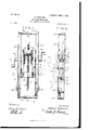
- Figure 1 is afront elevation tional view through the machine on the line 4 4 one of the side bars'of the frame 1.
- frame consists of two sections, one of which is approximately rectangular, being formed with horizontal end bars connected by vertical side bars. This section is designated by the reference-numerall, and formed with the opposite side bars are oppositely-disposed tubular bearings 2 and 3, which carry shafts 4and 5, extending therethrough.
- tubular bearings 2 and 3 which carry shafts 4and 5, extending therethrough.
- beveled gears 6 and 7 On the inner ends I of the respective shafts 4 and 5 are beveled gears 6 and 7, which mesh with a h alsoallyarranged beveled gear 8, formed with a central opening, on the edge of which is a feather
- the second member of the frame comprises two hinged bars 12 and 13, which are connected by a vertical bar 14, alining or coinciding with These bars 12 and 13 are hinged to the opposite bar by a vertically-extending rod or pintle 15, which projects through the lugs16 on the frame 1 and through the ends of the bars 12 and 13.
- the end bars of the two frame-sections are formed with alining semicircular concave portions or grooves 17 and 18, which are threaded internally, so that when the two frame-sections are brought together and fastened by the catch 19 alining internallythreaded guide-openings are formed for the vertically-adjustable bit-rod 11.
- the vertical or side bars of the frame 1 are cut away near their extremities to form seats or rabbets 20 and 21 to receive the transverse bars 12 and 13 of the second frame-section.
- the two sections can be rigidly fastened to each other, so as to form firm bearings for the gearing-shafts when all the parts are properly assembled.
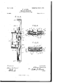
- a drill of the character invented by me is required to perform its work under varying conditions, generally to the unequal depths or thicknesses of the stone, it is and 29, which pass through the arms near necessary to provide an adjustable supporting means for the mechanism, whereby the drillframe and its appurtenances can be adjustably supported to accommodate the drill to the particular condition existing at the time of its operation.
- the device for effecting this result is termed a supporting-frame.
- This frame is formed by securing two parallel vertically-arranged bars or side rails 22 and 23 together by end battens or rails 24 and 25.
- the side rails 22 and 23 are provided with vertical elongated slots 25, which aline with each other and through which project the ournal-bearings 2 an d 3, carried by the frame-- section 1.
- I provide parallel swinging and pivoted supporting-arms 26 and 27, which are pivoted near their upper extremities to the side rails 22 and 23.
- the arms 26 and 27 can be rigidly fastened to the side rails, however, by mcansof thumb-screws or pins 28 their lower extremities and the shanks of which extend into the side rails 22 and 23.
- These arms are formed intermediate their ends with cut-out portions or notches 30, which form hearings or seats for the reception of the tubular journal-bearings 2 and 3, carried by the drill frame section 1.
- the drillframe can readily be adjusted vertically and the adjustment changed by removing the pins or screws 28 and 29 and swinging the arms 26 and 27 in a position similar to that shown in dotted lines in Fig. 2.
- the entire drill-frame can be swung at any angle on a vertical radius to meet various requirements.
- Suflicient power will be exerted upon the drill-rod 11 by the gears 6, 7, and 8, which are operated through the medium of the cranks 31 and 32 on the shafts 4 and 5.
- the lower one, 34, of said openings permitting the proper working of the bit and drill-rod in the truly vertical operations thereof, while the upper opening, 33, is for receiving suitable means, as a jack screw, for maintaining the supporting-frame of the machine in rigid position. If it is desired to drill a hole on a horizontal plane, it is only necessary to swing the drill-frame to the desired position and operate the cranks 31 and 32.
- a drilling-machine the combination with an outwardly and upwardly swinging drill-frame having oppositely-disposed journals, a supporting-frame provided with slots through which the journals project, and pivoted devices on the drill-frame formed with seats for the reception of the journals, said drill-frame being constructed of two sections, one of which is pivoted to swing laterally independently of the other section.
- a drilling-machine the combination of a supporting-frame having oppositely-disposed slots therein, an outwardly and upwardly swinging drill-frame having hollow journals projecting through the slots in the supporting-frame, gear-carrying shafts in the said journals, a drill-rod actuated thereby, and means for securing said journals at determinate points of adjustment with relation to the sides of the slotin the supporting-frame, said drill-frame being constructed of two sections, one of which is pivoted to swing laterally independently of the other section.
- a drilling-machine the combination with a drill-frame having oppositely-disposed journals; of asupporting-frame provided with vertical side rails having slots therein through which the journals project, and pivoted supporting-arms carried by the side rails of the supporting-frame and formed with seats for the reception of the journals of the drill-frame.
- the combination with a drill-frame having oppositely-disposed journals; of asupporting-frame provided with slots through which the journals project, and pivoted devices carried by the drill-frame and formed with seats for the reception of the journals which form pivots to permit the drillframe to swing in a vertical are.
Landscapes
- Engineering & Computer Science (AREA)
- Mechanical Engineering (AREA)
- Processing Of Stones Or Stones Resemblance Materials (AREA)
Description
PATENTED JUNE 7, 1904. W. HOLSTINE. DRILLING MACHINE.
APPLICATION FILED FEB. 21, 1903.
2 SEIIETS-SHEBT 1 N0 MODEL.
Fl e1- W1 T/VESSES:
. Atfomey in: Noam: Pzvzns o0, DNOTO LITHOu WASHINGTON. n. c
No. 762,169. PATENTED JUNE 7, 1904. W. HOLSTINB.
DRILLING MACHINE.
APPLICATION FILED FEB. 21, 1903.
mm By M9 THE No'nms PETERS co. PmTo-umu, WASNVNGTON n I:
Patented June 7, 1904.v
PATENT OFFICE.
VILLIAM HOLSTINE, OF STONE, WEST VIRGINIA.
DRILLING-MACHINE.
SPECIFICATION forming part of Letters Patent No. 762,169, dated June 7', 1904.
Application filed February 21, 1903. Serial No. 144,364:- (No model.)
To all whom it may concern:
Be it known that I, WVILLIAM HOLSTINE, a citizen of the United States, residing at Stone, in the county of Fayette and State of West Virginia, have invented new and useful Improvements in Drilling-Machines, of which the following is a specification.
This invention relates to drilling-machines, but more particularly to a machine which can be efficiently operated for mining minerals, such as coal, slate, stone, 620.
One of the principal objects of the invention is to produce a machine of this character possessing the advantageous features of accuracy and ease of manipulation.
Another object is to provide aportable drill which will possess all of the advantages usually found in the best type of machines of this character.
consists in providing a supporting or supplemental frame for the drill-frame having certain novel adjustments which permit the drill- 5 frame to accommodate itself to varying thicknesses of material to be drilled.
The invention further consists in providing a drill-frame of two sections which act as clamps for holding the operating mechanism p in proper relative position.
The invention further consists in arranging the drill-frame and swinging supports on the supporting or secondary frame so that the drill can be operated at any angle.
The manner of operating the drill, as well as the various positions of adjustment of which the drill-frame is susceptible, will be specifically set forth hereinafter and the novel features will be defined in the appended claims.
In the drawings, Figure 1 is afront elevation tional view through the machine on the line 4 4 one of the side bars'of the frame 1.
frame consists of two sections, one of which is approximately rectangular, being formed with horizontal end bars connected by vertical side bars. This section is designated by the reference-numerall, and formed with the opposite side bars are oppositely-disposed tubular bearings 2 and 3, which carry shafts 4and 5, extending therethrough. On the inner ends I of the respective shafts 4 and 5 are beveled gears 6 and 7, which mesh with a h orizontallyarranged beveled gear 8, formed with a central opening, on the edge of which is a feather With these objects in view the invention or spline 9, which works in the vertical groove 10 of the threaded auger-rod 11. The second member of the frame comprises two hinged bars 12 and 13, which are connected by a vertical bar 14, alining or coinciding with These bars 12 and 13 are hinged to the opposite bar by a vertically-extending rod or pintle 15, which projects through the lugs16 on the frame 1 and through the ends of the bars 12 and 13. ,The end bars of the two frame-sections are formed with alining semicircular concave portions or grooves 17 and 18, which are threaded internally, so that when the two frame-sections are brought together and fastened by the catch 19 alining internallythreaded guide-openings are formed for the vertically-adjustable bit-rod 11. It will be noticed that the vertical or side bars of the frame 1 are cut away near their extremities to form seats or rabbets 20 and 21 to receive the transverse bars 12 and 13 of the second frame-section. By providing such astructure the two sections can be rigidly fastened to each other, so as to form firm bearings for the gearing-shafts when all the parts are properly assembled.
Inasmuch as a drill of the character invented by me is required to perform its work under varying conditions, generally to the unequal depths or thicknesses of the stone, it is and 29, which pass through the arms near necessary to provide an adjustable supporting means for the mechanism, whereby the drillframe and its appurtenances can be adjustably supported to accommodate the drill to the particular condition existing at the time of its operation. The device for effecting this resultis termed a supporting-frame. This frame is formed by securing two parallel vertically-arranged bars or side rails 22 and 23 together by end battens or rails 24 and 25. The side rails 22 and 23 are provided with vertical elongated slots 25, which aline with each other and through which project the ournal-bearings 2 an d 3, carried by the frame-- section 1. In order that the drill-frame will be adjustably supported with relation to the secondary frame, I provide parallel swinging and pivoted supporting- arms 26 and 27, which are pivoted near their upper extremities to the side rails 22 and 23. The arms 26 and 27 can be rigidly fastened to the side rails, however, by mcansof thumb-screws or pins 28 their lower extremities and the shanks of which extend into the side rails 22 and 23. These arms are formed intermediate their ends with cut-out portions or notches 30, which form hearings or seats for the reception of the tubular journal- bearings 2 and 3, carried by the drill frame section 1. As these seats 30 are successively arranged along the length of the arms 26 and 27, the drillframe can readily be adjusted vertically and the adjustment changed by removing the pins or screws 28 and 29 and swinging the arms 26 and 27 in a position similar to that shown in dotted lines in Fig. 2. WV hen the proper point of ad justmcnthas been reached,the arms will be swung back to snugly rest against the side rails 22 and 23, in which position they can be secured by the pins or screws 28 and 29. As the seats 30 form supplemental bearings for the reception of the tubular bearings 2 and 3, and owing to the fact that these tubular bearings are a part of the drill-frame section 1, the entire drill-frame can be swung at any angle on a vertical radius to meet various requirements. Suflicient power will be exerted upon the drill-rod 11 by the gears 6, 7, and 8, which are operated through the medium of the cranks 31 and 32 on the shafts 4 and 5. Alining openings 33 and 34. are formed in the respective end battens 24and 25 of the secondary frame, the lower one, 34, of said openings permitting the proper working of the bit and drill-rod in the truly vertical operations thereof, while the upper opening, 33, is for receiving suitable means, as a jack screw, for maintaining the supporting-frame of the machine in rigid position. If it is desired to drill a hole on a horizontal plane, it is only necessary to swing the drill-frame to the desired position and operate the cranks 31 and 32.
It will be obvious from the foregoing that the drill can be operated in practically any position. I have described and illustrated what to me at this time appears to be the very best means of accomplishing the desired result; but I reserve the right to make such changes and alterations as may suggest themselves from time to time and fairly fall in the scope of the appended claims.
Having thus described the invention, what is claimed as new is- 1. In a drilling-machine, the combination with an outwardly and upwardly swinging drill-frame having oppositely-disposed journals, of a supporting-frame provided with vertical side rails having slots therein through which the journals project, and pivoted supporting-arms carried by the side rails and formed with seats for the reception of the journals of the drill-frame, the latter being constructed of two sections, one of which is pivoted to swing laterally independently of the other section.
2. In a drilling-machine, the combination with an outwardly and upwardly swinging drill-frame having oppositely-disposed journals, a supporting-frame provided with slots through which the journals project, and pivoted devices on the drill-frame formed with seats for the reception of the journals, said drill-frame being constructed of two sections, one of which is pivoted to swing laterally independently of the other section.
3. In a drilling-machine, the combination of a supporting-frame having oppositely-disposed slots therein, an outwardly and upwardly swinging drill-frame having hollow journals projecting through the slots in the supporting-frame, gear-carrying shafts in the said journals, a drill-rod actuated thereby, and means for securing said journals at determinate points of adjustment with relation to the sides of the slotin the supporting-frame, said drill-frame being constructed of two sections, one of which is pivoted to swing laterally independently of the other section.
4. In a drilling-machine, the combination with a drill-frame having oppositely-disposed journals; of asupporting-frame provided with vertical side rails having slots therein through which the journals project, and pivoted supporting-arms carried by the side rails of the supporting-frame and formed with seats for the reception of the journals of the drill-frame.
5. In a drilling-machine, the combination with a drill-frame having oppositely-disposed journals; of asupporting-frame provided with slots through which the journals project, and pivoted devices carried by the drill-frame and formed with seats for the reception of the journals which form pivots to permit the drillframe to swing in a vertical are.
6. In a drilling-machine, the combination with a supporting-frame having oppositelydisposed slots therein; of a drill-frame, hollow In testimony whereof I aifiX my signature in journals projecting through the slots in the presence of two witnesses. supporting-frame, gear-carrying shafts in the hollow journals, a drill-rod actuated thereby, WILLIAM HOLSTINE and means for securing the hollow journals at Witnesses:
determined points of adjustment with relation FRED HILL,
to the slots in the supporting-frame. J. A. NUTTER.
Priority Applications (1)
| Application Number | Priority Date | Filing Date | Title |
|---|---|---|---|
| US14436403A US762169A (en) | 1903-02-21 | 1903-02-21 | Drilling-machine. |
Applications Claiming Priority (1)
| Application Number | Priority Date | Filing Date | Title |
|---|---|---|---|
| US14436403A US762169A (en) | 1903-02-21 | 1903-02-21 | Drilling-machine. |
Publications (1)
| Publication Number | Publication Date |
|---|---|
| US762169A true US762169A (en) | 1904-06-07 |
Family
ID=2830655
Family Applications (1)
| Application Number | Title | Priority Date | Filing Date |
|---|---|---|---|
| US14436403A Expired - Lifetime US762169A (en) | 1903-02-21 | 1903-02-21 | Drilling-machine. |
Country Status (1)
| Country | Link |
|---|---|
| US (1) | US762169A (en) |
-
1903
- 1903-02-21 US US14436403A patent/US762169A/en not_active Expired - Lifetime
Similar Documents
| Publication | Publication Date | Title |
|---|---|---|
| US1294154A (en) | Post-hole-boring machine. | |
| US762169A (en) | Drilling-machine. | |
| US596375A (en) | James mfrchie | |
| US658782A (en) | Auger-cutter. | |
| US599914A (en) | nitschjmann | |
| US135313A (en) | Improvement in drilling-machines | |
| US49060A (en) | Improvement in boring-machines | |
| US749821A (en) | Drilling-machine | |
| US404188A (en) | Ground-auger | |
| US83671A (en) | Improvement in mortising-and-tenoning machine | |
| US735896A (en) | Boring-machine. | |
| US677444A (en) | Stone-cutting machine. | |
| US307762A (en) | bareness | |
| US474222A (en) | Blind-stile-boring machine | |
| US753058A (en) | flocke | |
| US639267A (en) | Mining-machine. | |
| US754753A (en) | Portable mortising chain cutter. | |
| USRE5499E (en) | Improvement in coal-drilling machines | |
| US433612A (en) | Mining-machine | |
| US360177A (en) | Supporting-column for drilling-machines | |
| US802197A (en) | Coal-drill. | |
| US611173A (en) | Drilling-machine | |
| US511364A (en) | shantz | |
| US564879A (en) | Drilling-machine | |
| US248812A (en) | t unstill |