US7620877B2 - Signal decoding methods and apparatus - Google Patents
Signal decoding methods and apparatus Download PDFInfo
- Publication number
- US7620877B2 US7620877B2 US11/261,540 US26154005A US7620877B2 US 7620877 B2 US7620877 B2 US 7620877B2 US 26154005 A US26154005 A US 26154005A US 7620877 B2 US7620877 B2 US 7620877B2
- Authority
- US
- United States
- Prior art keywords
- trellis
- states
- received signal
- probabilities
- time
- Prior art date
- Legal status (The legal status is an assumption and is not a legal conclusion. Google has not performed a legal analysis and makes no representation as to the accuracy of the status listed.)
- Expired - Fee Related, expires
Links
Images


Classifications
-
- H—ELECTRICITY
- H04—ELECTRIC COMMUNICATION TECHNIQUE
- H04L—TRANSMISSION OF DIGITAL INFORMATION, e.g. TELEGRAPHIC COMMUNICATION
- H04L1/00—Arrangements for detecting or preventing errors in the information received
- H04L1/004—Arrangements for detecting or preventing errors in the information received by using forward error control
- H04L1/0045—Arrangements at the receiver end
- H04L1/0047—Decoding adapted to other signal detection operation
- H04L1/005—Iterative decoding, including iteration between signal detection and decoding operation
-
- H—ELECTRICITY
- H03—ELECTRONIC CIRCUITRY
- H03M—CODING; DECODING; CODE CONVERSION IN GENERAL
- H03M13/00—Coding, decoding or code conversion, for error detection or error correction; Coding theory basic assumptions; Coding bounds; Error probability evaluation methods; Channel models; Simulation or testing of codes
- H03M13/37—Decoding methods or techniques, not specific to the particular type of coding provided for in groups H03M13/03 - H03M13/35
- H03M13/39—Sequence estimation, i.e. using statistical methods for the reconstruction of the original codes
- H03M13/3905—Maximum a posteriori probability [MAP] decoding or approximations thereof based on trellis or lattice decoding, e.g. forward-backward algorithm, log-MAP decoding, max-log-MAP decoding
-
- H—ELECTRICITY
- H03—ELECTRONIC CIRCUITRY
- H03M—CODING; DECODING; CODE CONVERSION IN GENERAL
- H03M13/00—Coding, decoding or code conversion, for error detection or error correction; Coding theory basic assumptions; Coding bounds; Error probability evaluation methods; Channel models; Simulation or testing of codes
- H03M13/37—Decoding methods or techniques, not specific to the particular type of coding provided for in groups H03M13/03 - H03M13/35
- H03M13/39—Sequence estimation, i.e. using statistical methods for the reconstruction of the original codes
- H03M13/3955—Sequence estimation, i.e. using statistical methods for the reconstruction of the original codes using a trellis with a reduced state space complexity, e.g. M-algorithm or T-algorithm
-
- H—ELECTRICITY
- H03—ELECTRONIC CIRCUITRY
- H03M—CODING; DECODING; CODE CONVERSION IN GENERAL
- H03M13/00—Coding, decoding or code conversion, for error detection or error correction; Coding theory basic assumptions; Coding bounds; Error probability evaluation methods; Channel models; Simulation or testing of codes
- H03M13/37—Decoding methods or techniques, not specific to the particular type of coding provided for in groups H03M13/03 - H03M13/35
- H03M13/45—Soft decoding, i.e. using symbol reliability information
-
- H—ELECTRICITY
- H04—ELECTRIC COMMUNICATION TECHNIQUE
- H04L—TRANSMISSION OF DIGITAL INFORMATION, e.g. TELEGRAPHIC COMMUNICATION
- H04L1/00—Arrangements for detecting or preventing errors in the information received
- H04L1/004—Arrangements for detecting or preventing errors in the information received by using forward error control
- H04L1/0045—Arrangements at the receiver end
- H04L1/0047—Decoding adapted to other signal detection operation
- H04L1/0048—Decoding adapted to other signal detection operation in conjunction with detection of multiuser or interfering signals, e.g. iteration between CDMA or MIMO detector and FEC decoder
-
- H—ELECTRICITY
- H04—ELECTRIC COMMUNICATION TECHNIQUE
- H04L—TRANSMISSION OF DIGITAL INFORMATION, e.g. TELEGRAPHIC COMMUNICATION
- H04L1/00—Arrangements for detecting or preventing errors in the information received
- H04L1/004—Arrangements for detecting or preventing errors in the information received by using forward error control
- H04L1/0045—Arrangements at the receiver end
- H04L1/0055—MAP-decoding
-
- H—ELECTRICITY
- H04—ELECTRIC COMMUNICATION TECHNIQUE
- H04L—TRANSMISSION OF DIGITAL INFORMATION, e.g. TELEGRAPHIC COMMUNICATION
- H04L1/00—Arrangements for detecting or preventing errors in the information received
- H04L1/02—Arrangements for detecting or preventing errors in the information received by diversity reception
- H04L1/06—Arrangements for detecting or preventing errors in the information received by diversity reception using space diversity
- H04L1/0618—Space-time coding
- H04L1/0631—Receiver arrangements
-
- H—ELECTRICITY
- H04—ELECTRIC COMMUNICATION TECHNIQUE
- H04B—TRANSMISSION
- H04B7/00—Radio transmission systems, i.e. using radiation field
- H04B7/02—Diversity systems; Multi-antenna system, i.e. transmission or reception using multiple antennas
- H04B7/04—Diversity systems; Multi-antenna system, i.e. transmission or reception using multiple antennas using two or more spaced independent antennas
- H04B7/06—Diversity systems; Multi-antenna system, i.e. transmission or reception using multiple antennas using two or more spaced independent antennas at the transmitting station
-
- H—ELECTRICITY
- H04—ELECTRIC COMMUNICATION TECHNIQUE
- H04B—TRANSMISSION
- H04B7/00—Radio transmission systems, i.e. using radiation field
- H04B7/02—Diversity systems; Multi-antenna system, i.e. transmission or reception using multiple antennas
- H04B7/04—Diversity systems; Multi-antenna system, i.e. transmission or reception using multiple antennas using two or more spaced independent antennas
- H04B7/08—Diversity systems; Multi-antenna system, i.e. transmission or reception using multiple antennas using two or more spaced independent antennas at the receiving station
Definitions
- This invention generally relates to methods, apparatus and computer program code for decoding signals, and more particularly to trellis-based decoding using a variant of a BCJR procedure.
- a trellis diagram comprises a sequence of sets of states indexed by time, the states representing states of a data encoder and transitions between the states representing encoded data.
- a trellis decoder generally (but not necessarily) provides information on the probability of data symbols (transitions) or of individual trellis states since such soft information can be used as a priori information for iteratively improving a decoding process.
- the BCJR procedure (named after the inventors) provides trellis decoding assuming Markov data (where the evolution of a state depends on the current state but not its history).
- a channel codec is employed to improve the performance of the receiver. Therefore, for most receivers, especially iterative receivers, a soft output detector/decoder/equaliser is required to provide the soft input to the channel decoder.
- the BCJR algorithm L. Bahl, J. Cocke, F. Jelinek and J. Raviv, “Optimal decoding of linear codes for minimizing symbol error rate,” IEEE Trans. Information Theory , vol. 20, pp. 284-287, March 1974
- the encoder with memory can be the channel encoder or the dispersive channel.
- the BCJR is an efficient and optimal algorithm for maximum a posteriori state estimation under the assumption of a hidden Markov chain with a discrete state space. It solves a trellis representation of the system by a forward recursion through each trellis stage (successive trellis stages corresponding to successive time instants) followed by a backward recursion through the trellis stages. This is described in more detail later. However in many applications there is a large number of possible states at each trellis stage.
- M-BCJR M-BCJR algorithm
- V. Franz and J. B. Anderson, “Concatenated decoding with a reduced-search BCJR algorithm,” IEEE Journal on Selected Areas in Commun ., vol. 16, pp. 186-195, February 1998) which computes the recursions in the BCJR algorithm for only M states (a subset of the full set of trellis states) at every trellis stage.
- the M states are selected based on a metric of the BCJR algorithm, more particularly at a time t selecting the M states with the largest forward recursion parameter ⁇ t .
- the inventors have recognised that the M-BCJR algorithm selects its active states based on the filtered distribution of states up to that time instance and therefore makes a premature choice of the states selection.
- a trellis decoder for decoding symbols of a received signal, said symbol comprising a sequence defined by transitions between states of a trellis
- the trellis decoder comprising: means for performing a forward recursion through said trellis to determine a first set of probabilities ( ⁇ (X t )) each defining a probability of a said trellis state (X t ) responsive to one or more current or earlier received signal values (y 1:t ); means for providing a second set of ( ⁇ (X t )) probabilities each defining a probability of one or more received signal values (y t+1:T ) given an earlier said trellis state (X t ); means to decode said received signal to determine probabilities (p(b t
- the means for providing the second set of probabilities ( ⁇ (X t )) comprises means for performing a backwards recursion through the trellis to determine the probabilities.
- this backwards recursion may be omitted and instead, for example, fixed probabilities for ⁇ (X t ) employed to implement, say, an improved type of soft output Viterbi.
- the second set of probabilities ( ⁇ (X t )) may be provided by, say, a stored number, and all the probabilities ⁇ (X t ) may be set to the same value.
- the selection of states is more particularly responsive to one or more current or earlier received signal values y (1:t) in addition to the one or more received signal values later than the relevant trellis state.
- Embodiments of the trellis decoder provide a reduced state variation of the BCJR procedure with improved performance in which a set of active states is selected at each time instance (trellis stage) in the forward recursion using received signals in the immediate future of the relevant time instant (trellis stage).
- the procedure looks over a predetermined time interval (a fixed lag), which may be selected, for example, responsive to the channel memory.
- a smoothed distribution of states and/or state transitions is assumed at each time instance, which facilitates the use of a computationally simple Gaussian approximation, as described in more detail later.
- this procedure is robust with respect to the memory or energy distribution of the underlying system and provides a performance approaching that of the conventional, optimal procedure but with only a fraction of the complexity.
- the procedure estimates a fixed lag smoothed distribution of the states (and state transitions) with a lag greater than zero. Then an active state (and state transition) selection is performed using these fixed lag smoothed distributions. Thereafter the metrics of the BCJR algorithm are computed only for the selected, active states.
- the backward recursion of the algorithm is similar to conventional BCJR but, again, is only carried out over the selected active states. In this way embodiments of the invention use only a fraction of the total states, thus reducing the complexity of the trellis based decoding whilst retaining a near-optimal performance. This is achieved by the use of future information obtained through the fixed lag smoothed distribution of states and state transitions and in this way the information loss through premature state selection is reduced.
- the means to select states employs a Gaussian approximation to determine a likelihood of a trellis state from the future received signal values (in effect, treating the transmitted symbols as Gaussian random variables to reduce complexity, although in reality, this is not necessary always true).
- the selection of states may be made by selecting transitions from previous trellis states (at a previous trellis stage). A transition defines a transmitted symbol and a further selection of state transitions may be made using the probability of a particular transmitted symbol given the previous trellis state and received signal values from a current time forward over the fixed time lag interval.
- Preferably states are further selected (at a current trellis stage) responsive to a probability of a particular state given the one or more later received signal values, and more particularly given a sequence of received signal values from an initially processed value through a current value to a future value a fixed time lag interval ahead of the current value.
- states are selected based upon p(X t
- a further selection of state transitions is made from a set of selected states of time (t ⁇ 1) by selecting from p(b t
- the selection of states may be made dependent upon one or more log probability metrics dependent upon the one or more received signal values later than a time instant defined by a current trellis stage since this can reduce computational complexity.
- the trellis decoding is applied iteratively, using a string of transmitted symbol probabilities given the received signal string as a priori information for another iteration of the decoding, with the aim of producing more accurate probabilities.
- the output of a trellis decoder comprises soft (probability) information rather than hard information, although in embodiments the decoder may be configured to provide a (most likely) estimated transmitted symbol sequence output.
- states at a current time are preferably selected responsive to a probability of the state given one or more later signal values, or more particularly given a sequence of signal values from an initial time to a future time ahead of the current time by a fixed time lag interval.
- This probability may be determined from a probability of a sequence of received signal values from a current time to a future time a fixed time lag interval ahead of the current time, given a previous (t ⁇ 1) state. In preferred embodiments this latter probability is assumed to have a normal distribution, which simplifies the computational procedure.
- the multivariate normal distribution may be described by a mean vector and a covariance matrix.
- the covariance matrix becomes time dependent.
- the determination of the relevant probability (or equivalently a probability metric) requires a matrix inversion and thus for applications of this type the decoder preferably also includes means for extrapolating a value for the inverted covariance matrix at a particular time interval from its value at a previous time, this again reducing computational complexity.
- X t ⁇ 1 ) may be approximated by a multivariate normal distribution with a covariance matrix ⁇ t , with means for extrapolating a value of an inverse of said matrix from a value at one said trellis state to a value at a later said trellis state.
- the probability of the transmitted symbols given a particular selected state of earlier time instance and future received signals may evaluated by considering how the distribution factorises across the symbols transmitted, that is approximating p(b t
- j labels, for example, the jth component of a sequence of symbols (such as space-time symbols) transmitted together.
- X t ⁇ 1 ,y t:t+L ′) may be approximated by a multivariate normal distribution with a covariance matrix ⁇ t,j , with means for extrapolating a value of an inverse of the matrix from the value the inverse of the matrix ⁇ t .
- a received signal value comprises a vector of signals received over a MIMO (Multiple Input Multiple Output) channel, or in general a vector of signals in a receiver having multiple observations pertaining to a single time instance.
- This vector may define, for example, a space-time symbol in a spatially multiplex MIMO communications system such as a system in which multiple transmit antennas/data streams are transmitted by a single user/transmitter.
- the decoder may be employed for multi-user detection, for example where multiple users each with a single transmit antenna transmit at the same time (in this case the symbols transmitted over the different channels, for example from users with different spreading sequences, are then uncorrelated).
- the decoder may be employed for decoding transmitted signals with other diversities such as CDMA, in which signals from multiple users, optionally employing multiple antennas, differentiated by their unique spreading sequence codes, are received at a receiver. This is because channel effects can reduce orthogonality of the received signals so that additional processing may be necessary to differentiate the signals from the different users.
- Embodiments of the decoder may also be employed in OFDM (Orthogonal Frequency Division Multiplexed) MIMO or other communication systems.
- Embodiments of a trellis decoder as described above may be employed for trellis-based decoding of a space-time code and/or a channel code, and/or equalisation. In some preferred embodiments joint equalisation and decoding of a channel coded and/or space-time coded system is performed.
- the above described decoder provide reduced complexity decoding for any “encoder” which can be represented by a trellis diagram.
- Particular applications of embodiments of the decoder include a turbo decoder for example of the type required by UMTS (Universal Mobile Telecommunications System) or some wireless LAN (Local area Network) standards, and equalises, for example of the type required by the EDGE (Enhanced Data for Global Evolution) standard.
- the invention provides a method of decoding symbols of a received signal, said symbols comprising a sequence defined by transitions between states of a trellis, each said trellis state being associated with a time, the method comprising: performing a forward recursion through said trellis to determine a first set of probabilities each defining a probability of a said trellis state responsive to prior values of said received signal; obtaining a second set of probabilities each defining a probability of one or more received signal values given a prior said trellis state; and decoding said received signal to determine probabilities for symbols of a corresponding transmitted sequence of symbols from said first and second sets of probabilities; the method further comprising: selecting states for determining said first set of probabilities responsive to one or more received signal values later than a said trellis state defining a probability in said first set.
- obtaining the second set of probabilities comprises performing a backwards recursion through the trellis to determine the probabilities.
- each probability is associated with a trellis state and the states for processing are based upon received signal values from future times (each trellis state being associated with a respective time), that is times later than that of the relevant state.
- the invention provides a method of decoding a trellis coded signal using a BCJR-type procedure in which probabilities of transmitted symbols are determined by forwards and backwards iteration through a trellis having successive sets of states associated with successive received signal time intervals, a set of states defining a trellis stage, the method comprising reducing the number of states processed at a said trellis stage (X t ) by selecting states for evaluation for determining said probabilities based upon future received signal values (y t:t+L ′) at said stage.
- the selecting of states comprises selecting transitions from a previously selected set of states in a previous trellis stage, preferably followed by further selection from among the states selected by selecting transitions.
- This further selection is preferably responsive to a probability of a state (in a current trellis stage) conditioned on the (one or more) future received signal values (and preferably also on a current received signal value).
- a normal distribution is assumed for the future received sequence.
- a determined probability in embodiments comprises a log probability; in some preferred embodiments the selecting of transitions and/or states comprises evaluating one or more log probability metrics.
- the invention further provides a decoder configured to implement the above described methods, and in particular including means for implementing the features of the methods.
- the invention also provides a decoder for decoding a trellis coded signal using a BCJR type procedure in which probabilities of transmitted symbols are determined by forwards and backwards iteration through a trellis having successive sets of states associated with successive received signal time intervals, a set of states defining a trellis stage, the decoder including a system to reduce the number of states processed at a said trellis stage (X t ) by selecting states for evaluation for determining said probabilities based upon future received signal values (y t:t+L ′) at said stage, more particularly as well as the received values so far (y 1:t ⁇ 1 ).
- the invention further provides a trellis decoder for decoding a trellis coded signal using a BCJR type procedure in which probabilities of transmitted symbols are determined by forwards and backwards iteration through a trellis having successive sets of states associated with successive received signal time intervals, a set of states defining a trellis stage, the decoder comprising: a received signal input for said trellis coded signal; an output for providing decoded signal data; program memory for storing processor control code; and a processor coupled to said received signal input, to said output and to said program memory for loading and implementing said code, said code comprising code to: reduce the number of states processed at a said trellis stage (X t ) by selecting states for evaluation for determining said probabilities based upon future received signal values (y t:t+L ′) at said stage, more particularly as well as the received values so far (y 1:t ⁇ 1 )
- the invention further provides a trellis decoder for decoding symbols of a received signal, said symbols comprising a sequence defined by transitions between states of a trellis each said trellis state being associated with a time
- the decoder comprising: a received signal input for said trellis coded signal; an output for providing decoded signal data; program memory for storing processor control code; and a processor coupled to said received signal input, to said output and to said program memory for loading and implementing said code, said code comprising code to: perform a forward recursion through said trellis to determine a first set of probabilities each defining a probability of a said trellis state responsive to prior values of said received signal; obtain a second set of probabilities each defining a probability of one or more received signal values given a prior said trellis state; and decode said received signal to determine probabilities for symbols of a corresponding transmitted sequence of symbols from said first and second sets of probabilities; the code further comprising code to: select states for
- the code to obtain the second set of probabilities may comprise code to perform a backwards recursion through said trellis to determine the probabilities, or may simply comprise code to assign a value, for example a fixed value, to each of said probabilities in said second set.
- the invention further provides a receiver incorporating a decoder as described above.
- the invention further provides processor control code to implement the above-described decoders and methods; and a trellis data structure storing BCJR trellis data for trellis states comprising substantially only those states which are selected by a decoder/method according to an embodiment of the invention.
- This code (and data) may be provided on a data carrier (sometimes referred to as a computer program product) such as a disk, CD- or DVD-ROM, programmed memory such as read-only memory (Firmware), or on a data carrier such as optical or electrical signal carrier.
- code (and data) to implement embodiments of the invention may comprise code in a conventional programming language such as C or, for example, code such as microcode.
- code to implement embodiments of the invention may alternatively comprise code for setting up or controlling an ASIC or FPGA, or code for a hardware description language such as Verilog (Trade Mark), VHDL (Very high speed integrated circuit Hardware Description Language) or SystemC.
- Verilog Trade Mark
- VHDL Very high speed integrated circuit Hardware Description Language
- SystemC SystemC
- embodiments of the above described decoders and methods may be implemented in software or in hardware, in a combination of the two.
- FIG. 1 shows an example of a MIMO communications system
- FIGS. 2 a to 2 c show, respectively, a portion of equalizer trellis according to an embodiment of the present invention, and first and second parts of a flow diagram of a procedure according to an embodiment of the present invention
- FIG. 3 shows a receiver incorporating an embodiment of a decoder in accordance with the present invention
- FIG. 4 shows a block diagram of a communications system incorporating an embodiment of a decoder according to the present invention configured for the equalisation of space-time coded and/or spatially multiplexed signals transmitted over a frequency selective channel;
- FIG. 5 shows a block diagram of a communications system incorporating an embodiment of a decoder according to the present invention configured for the detection of space-time coded and/or spatially multiplexed signals transmitted over a flat fading channel;
- FIG. 6 shows a block diagram of a communications system incorporating an embodiment of a decoder according to the present invention configured for trellis-based channel decoding
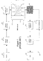
- FIG. 7 shows a block diagram of a communications system incorporating an embodiment of a decoder according to the present invention configured for the joint trellis-based decoding of the combined effect of a channel coder and a space-time coder and/or spatial multiplexer;
- FIG. 8 shows graphs of bit error rate and frame error rate against signal-to-noise ratio for a first communication system comparing the performance of an embodiment of the invention with prior art techniques
- FIG. 9 shows graphs of bit error rate and frame error rate against signal-to-noise ratio for a second communications system comparing the performance of embodiments of the invention against prior art techniques.
- X 1:t ) p(y t
- y t being independent of X t ⁇ 1 as well are thus a special case of this formulation.
- each state X t come from the set S X with cardinality
- ⁇ ⁇ ( X t ) p ⁇ ( y t + 1 : T
- X t ) ⁇ X t + 1 ⁇ S X ⁇ ⁇ ⁇ ( X t + 1 ) ⁇ ⁇ ⁇ ⁇ ( X t , X t + 1 ) are made.
- the A Posteriori probabilities of the states and state transitions can be evaluated by p(X t
- the complexity of this algorithm is linear in time T, it is also linear on
- the procedure selects M active states at each time instance in the forward recursion, but unlike the M-BCJR algorithm mentioned above, which selects the M active states which have the largest metric ⁇ (X t ), we use a fixed lag L′ smoothed distribution of states p(X t
- the lag L′ can be chosen to account for the memory of the system (for example responsive to the average duration of the channel impulse response) and can be a compromise between performance and complexity.
- FIG. 1 shows an example of a known MIMO data communications system 100 in which a data source 102 provides data to a channel encoder 104 typically comprising a convolutional coder such as a recursive systematic convolutional (RSC) encoder, or a stronger so-called turbo encoder (which includes an interleaver).
- the channel encoder 104 is in this example followed by a channel interleaver 106 and a space-time encoder 108 .
- the space-time encoder 108 encodes an incoming symbol or symbols as a plurality of code symbols for simultaneous transmission from each of a plurality of transmit antennas 110 and may be described in terms of an encoding machine which operates on the data to provide spatial and temporal transmit diversity.
- a modulator not shown
- Space-frequency encoding may additionally (or alternatively) be employed.
- the encoded transmitted signals propagate through MIMO channel 112 to receive antennas 114 , which provide a plurality of inputs to a space-time (and/or frequency) decoder 116 , which has the task of removing the effect of the encoder 108 and the MIMO channel 112 .
- the output of the decoder 116 comprises a plurality of signal streams, one for each transmit antenna, each carrying so-called soft or likelihood data on the probability of a transmitted symbol having a particular value. This is (here) provided to a channel de-interleaver 118 which reverses the effect of channel interleaver 106 , and then to a channel decoder 120 , conventionally for example a Viterbi decoder, which decodes the convolutional code.
- the channel decoder 120 may be a SIHO (soft-in hard-out) decoder that is receiving symbol (or bit) likelihood data and providing data on which a hard decision has been made.
- the output of channel decoder 120 is provided to a data sink 122 , for further processing of the data in any desired manner.
- turbo decoding may be employed, where a soft output from a SISO (soft-in soft-out) channel decoder 120 is provided to a channel interleaver 124 (corresponding to interleaver 106 ), which in turn provides soft (likelihood) data to decoder 116 for iterative space-time (and/or frequency) and channel decoding.
- Embodiments of a decoder as described herein may be employed to implement one or both (optionally combined or jointly) of ST decoder 116 and channel 120 , or may be employed for other decoding tasks.
- the equalizer's task in this scenario is to consider the received signal y t i and detect the transmitted symbols b t j .
- b t j is a real or complex number, as is y t i
- h(d) is an (n ⁇ m) matrix with the i th row and j th column component given by h i,j (d).
- an estimate of the matrix h can be obtained in a conventional manner, for example, using a training sequence transmitted from each transmit antenna in turn (to avoid interference problems), each time listening on all the receive antennas to characterise the channels from that transmit antenna to the receive antennas.
- orthogonal sequences may be transmitted simultaneously from all the transmit antennas (although this increases the complexity of the training as interference problems can then arise).
- the BCJR algorithm can be invoked to evaluate the a posteriori probabilities of the state transitions, which can be mapped to the a posteriori probabilities of the set of antenna symbols transmitted at each time instance.
- the algorithm we describe can, however, be implemented at a much-reduced practical complexity as explained below.
- the algorithm we describe has a forward recursion and a backward recursion through the trellis similar to the BCJR algorithm.
- the algorithm performs two functions: active state selection and the computation and storage of ⁇ (X t ) for the active states of time t and ⁇ (X t ⁇ 1 ,X t ) for state transitions from the active states at times t ⁇ 1 to t.
- ⁇ t ⁇ X t (1) ,X t (2) , . . . ,X t (M) ⁇
- the states that are contending to be active states be represented by ⁇ t , as shown in FIG. 2 a .
- a system that is terminated at a predetermined state for example, state 0 (a trellis terminated system) at the end of the frame.
- the general idea is to estimate the fix lag smoothed density of the states for the states in ⁇ t .
- the following derivations present one simple method of estimating these densities at a low complexity.
- Z is the normalization constant of the estimated density of p(X t
- a particular state X t ⁇ 1 renders the b s l known for s ⁇ [t ⁇ L, t ⁇ 1] and l ⁇ [1,m]. Due to the uncertainty of other antenna symbols, the true distribution of y t:t+L′ given X t ⁇ 1 is a mixture of normal distributions. We will approximate this true distribution with a single Gaussian distribution that has the same moments of the true distribution. That is we can say that p(y t:t+L′
- p s,i k is probability of the symbol transmitted by the l th antenna at time index s,b s l for s ⁇ [t,t+L′] and l ⁇ [1,m] being the symbol ⁇ k for k ⁇ [1,N].
- Equal symbol probabilities may be assumed unless other information is available, for example from a previous iteration of the decoding procedure and/or from a channel decoder.
- the state transition to time instance t is determined by the transmitted space-time symbol b t .
- the algorithm selects S transitions from each of the M states at time t ⁇ 1 using the estimation of the density p(b t
- p(b t ) is the prior probability of the space-time symbol b t which is transmitted from the state transition relevant to (X t ⁇ 1 ,X t ). In the absence of better information the space-time symbols may be considered equally likely.
- ⁇ (X t ) is computed for each state in ⁇ t using the relation:
- ⁇ ⁇ ( X t ) ⁇ X t + 1 ⁇ ⁇ t + 1 ⁇ ⁇ ⁇ ( X t + 1 ) ⁇ ⁇ ⁇ ⁇ ( X t , X t + 1 ) ( 12 )
- Z′ is the normalization constant of the estimated density of p(b t
- the a posteriori probability of each antenna symbol can be computed from these computed posterior probabilities of the space-time symbols as follows. Let us say the a posteriori probability density of the symbols transmitted by the antenna j at time instant t is given by the vector (q t,j 1 ,q t,j 2 , . . . ,q t,j N ), where q t,j k is the posterior probability of the particular antenna symbol being ⁇ k , for k ⁇ [1,N]. Then q t,j k for every t ⁇ 1, . . . ,T ⁇ , j ⁇ 1, . . . ,m ⁇ and k ⁇ 1, . . . ,N ⁇ can be calculated by summing space-time symbol probabilities over all the space-time symbols that result in the transmission of the antenna symbol ⁇ k from antenna j.
- the probability of a particular bit having a particular binary value may be obtained by summing symbol probabilities over all the symbols in which that bit has that particular binary value.
- FIGS. 2 b and 2 c which summarise the steps of the procedure (in FIGS. 2 b and 2 c the numbering of the steps corresponds to that given below).
- N it number of iterations of the proposed algorithm is performed (though in some embodiments N it may equal one).
- Equation (9a) and (9b) that employs exponential function, which is costly for implementation. This can be avoided as explained below.
- the selection of active states ⁇ t involves selecting S active state transition with largest p(b t
- X t ⁇ 1 ,y t:t+L′ ) can be represented as:
- the computation of the inversions of the matrices ⁇ circumflex over ( ⁇ ) ⁇ t,j and ⁇ tilde over ( ⁇ ) ⁇ t for each transmit antenna and for each time instant can be a computationally intensive task.
- One method of avoiding computing these inversions at each time instance in the case of implementations with uniform prior distributions for the space-time symbols and when the total state space is very large is to increase the number of active states (M) instead of going into an iterative implementation.
- the BCJR algorithm includes forward and backward recursion through the trellis to determine the probabilities for the estimated symbols.
- the backward recursion of the algorithm can be ignored and thus the contribution of the backward recursion metrics ⁇ (X t ) in the computation of the a posteriori probability of the space-time symbols in Equation (13) is not included. Therefore this reduced complexity version is similar to the soft output Viterbi algorithm which finds the best survivor path in the trellis.
- FIG. 3 shows a receiver 300 incorporating an embodiment of a decoder in accordance with the invention.
- Receiver 300 comprises one or more receive antennas 302 a, b (of which two are shown in the illustrated embodiment) each coupled to a respective rf front end 304 a, b , and thence to a respective analogue-to-digital converter 306 a,b and to a digital signal processor (DSP) 308 .
- DSP 308 will typically include one or more processors 308 a (for example, for a parallel implementation) and some working memory 308 b .
- the DSP 308 has a data output 310 and an address, data and control bus 312 to couple the DSP to permanent program memory 314 such as flash RAM or ROM.
- Permanent program memory 314 stores code and optionally data structures or data structure definitions for DSP 308 .
- program memory 314 includes trellis-based BCJR-type (space time) decoder code 314 a comprising state selection code, forward recursion parameter computation code, backward recursion parameter computation code, and transmit symbol probability estimation code to, when running on DSP 308 , implement corresponding functions as described above.
- Program memory 314 also includes MIMO channel estimation code 314 b to provide a MIMO channel estimate H, and optionally (depending upon the type of encoding applied) de-interleaver code 314 c , interleaver code 314 d , and channel decoder code 314 e . Examples of suitable code 314 e are well known to those skilled in the art.
- the decoder code may additionally or alternatively implement channel decoding and equalisation.
- embodiments of the described decoder may be applied in many types of communication system, not just MIMO systems.
- the code in permanent program memory 314 may be provided on a carrier such as an optical or electrical signal carrier or, as illustrated in FIG. 3 , a floppy disk 316 .
- the data output 310 from DSP 308 is provided to further data processing elements of receiver 300 (not shown in FIG. 3 ) as desired. These may include a baseband data processor for implementing higher level protocols.
- the receiver front-end will generally be implemented in hardware whilst the receiver processing will usually be implemented at least partially in software, although one or more ASICs and/or FPGAs may also be employed.
- ASICs and/or FPGAs may also be employed.
- All the functions of the receiver could be performed in hardware and that the exact point at which the signal is digitised in a software radio will generally depend upon a cost/complexity/power consumption trade-off.
- FIGS. 4 to 7 show some examples of applications of the above described decoder/method in MIMO systems.
- the examples are non-exhaustive and the same examples are applicable to communication systems with a single transmit antenna.
- FIG. 4 shows application of the above decoding procedure for the equalisation of space-time coded and/or spatially multiplexed signals transmitted over a frequency selective channel
- FIG. 5 shows application of the above decoding procedure for the detection of space-time coded and/or spatially multiplexed signals transmitted over a flat fading channel
- FIG. 6 shows application of the above decoding procedure for trellis-based channel decoding
- FIG. 7 shows application of the above decoding procedure for the joint trellis-based decoding of the combined effect of a channel coder and a space-time coder and/or spatial multiplexer.
- FIGS. 8 a and 8 b show graphs of (uncoded) bit error rate (BER, FIG. 8 a ) and (uncoded) frame error rate (FER, FIG. 8 b ) against signal-to-noise ratio in dB.
- the graphs show the results of a simulation of a 2 ⁇ 2 (two transmit antenna, two receive antenna) system in a 5-tap quasistatic Rayleigh fading channel, each transmit antenna transmitting BPSK (binary phase shift keying) modulated symbols.
- BER bit error rate
- FER frame error rate
- FIGS. 9 a to 9 d show graphs of uncoded and coded bit error rate (BER, FIGS. 9 a and 9 c respectively) and uncoded and coded frame error rate (FER, FIGS. 9 b and 9 d respectively), against signal-to-noise ratio in dB.
- the graphs show the results of a simulation of a 1 ⁇ 1 (single transmit antenna, single receive antenna) system transmitting 8PSK symbols into a 3-tap channel (curves 9 xxa), a 5-tap channel (curves 9 xxb), and a 10-tap channel (curves 9 xxc).
- the optimal BCJR equalizers for the respective 3, 5 and 10-tap channels have a total of 64, 4096 and over 134 million states.
- MMSE minimum mean square error
- Applications of embodiments of the invention include MIMO and non-MIMO receivers, for any type of signal which is susceptible to trellis-based decoding and include applications in base stations, access points, mobile terminals, wireless networks including PANs (personal area networks) and LANs (local area networks) and applications in third and fourth generation mobile phone networks.
- PANs personal area networks
- LANs local area networks
- embodiments of the invention facilitate cheaper receivers and/or improved performance, for example increased data rates without correspondingly increased complexity and cost.
- Embodiments of the invention may also potentially find application in other non-radio communication systems, for example a disk drive with multiple read heads and/or multiple data recording layers (which act like one or more transmitters).
Abstract
Description
with p(X0) being the initial state probability density. In other words at each time instant t we also have the conditional independence p(yt|X1:t)=p(yt|Xt−1,Xt). Situations with yt being independent of Xt−1 as well are thus a special case of this formulation. Here, the notation At:t+B refers to the sequence of states or symbols from time t to t+B, i.e At:t+B={At, At+1, . . . , At+B}. Let each state Xt come from the set SX with cardinality |SX|. When the sequence y1:T is observed, a linear time algorithm for the evaluation of the a posteriori probabilities p(Xt|y1:T) and p(Xt−1,Xt|y1:T) for all Xt−1,XtεSX and tε{1,. . . ,T} is the BCJR algorithm [1]. This algorithm involves a forward recursion through the trellis formed by the possibilities of the state sequence X0:T, in which the computation γ(Xt−1,Xt)=p(Xt,yt|Xt−1) and the recursive calculations of the metric
are made, and a backward recursion in which the recursive calculations of the metric
are made. Thereafter the A Posteriori probabilities of the states and state transitions can be evaluated by p(Xt|yt:T)∝α(Xt)β(Xt) and p(Xt−1,Xt|y1:T)∝α(Xt−1) γ(Xt−1,Xt)β(Xt) for all Xt−1,XtεSX and tε{1, . . . ,T}. Although the complexity of this algorithm is linear in time T, it is also linear on |SX| which can be millions in some practical problems such as the equalization of MIMO systems. Thus there are many practical applications in which the algorithm cannot be implemented cost effectively.
the BCJR algorithm can be invoked to evaluate the a posteriori probabilities of the state transitions, which can be mapped to the a posteriori probabilities of the set of antenna symbols transmitted at each time instance. The algorithm we describe can, however, be implemented at a much-reduced practical complexity as explained below.
y t:t+L′ =Ab+w (4)
where the noise vector and the transmitted symbol vector are given by w=((wt 1,wt 2, . . . ,wt+L′ 1, . . . ,wt−L′ n)⇑, b=(bt−L 1,bt−L 2, . . . ,bt+L′ 1, . . . ,bt+L′ m)⇑ respectively, and the form of A can be identified from (1). Thus, A is a n(L′+1)×m(L′+L+1) Toeplitz matrix given by:
where the (n×m) matrix h(d) has ith row and jth column component given by hi,j(d).
where Σ is the covariance matrix of w and (•)H denotes conjugate transpose operation ({tilde over (μ)}t is a vector of length n(L′+1) and {tilde over (Σ)}t is a n(L′+1)×n(L′+1) matrix).
and again noting that particular state Xt−1 renders the bs l known for sε[t−L,t−1] and lε[1,m], we can assume that p(ht jbt j|Xt−1,yt:t+L′) is having a normal distribution with the corresponding mean {circumflex over (μ)}t,j and covariance {circumflex over (Σ)}t,j given by:
where γ(Xt−1,Xt) is computed as
γ(X t−1 ,X t)=p(y t |X t−1 ,X t)p(X t |X t−1) (11a)
-
- Step 1: Select the parameters L′, M, S and Nit.
- Step 2: Set the iteration counter Cit to 1.
- Step 3: Set t=1. Set X0 (h)=0 (or some other starting state) for h=1, . . . ,M and set α(X0=0)=1 and α(X0≠0)=0.
- Step 4: When yt+L′ is received, compute the estimates of p(yt:t+L′|Xt−1) and p(bt j|Xt−1,yt:t+L′) for every jε[1,m],Xt−1εΩt−1 and bt jεB using the Gaussian approximations described in Equation (9a) and (9b). Compute p(bt|Xt−1,yt:t+L′) from Equation (3).
- Step 5: For each Xt−1εΩt−1, select the S largest p(bt|Xt−1,yt:t+L′) and consider the corresponding state transitions to be active. Thereby determine the states of Ξt.
- Step 6: Compute the estimate of p(Xt|y1:t+L′) for every state XtεΞt using (2). Select the M distinct states that have the largest fix lag-smoothed probability and include them in Ω1.
- Step 7: Compute γ(Xt−1,Xt) using (11b) for every Xt−1εΩt−1,XtεΩt and α(Xt) using (10) for every XtεΩt. Store these values.
- Step 8: If t<T−L′, increase t by one and go to
Step 4, otherwise continue to Step 9. - Step 9: If T−L′≦t<T, increase t by one, consider yt+L′to be received as
value 0 and go toStep 4; otherwise continue to Step 10. - Step 10: If the
state 0 is included in ΩT, set β(XT=0)=1 and β(XT≠0)=0 (set β mutatis mutandis for some other finishing state); otherwise set β(XT)=1 for all XTεΩT. - Step 11: Compute β(Xt−1) for every Xt−1εΩt−1 using (12).
- Step 12: Compute p(bt|y1:T) for every possible space-time symbol using (13).
- Compute the posterior probabilities of the antenna symbols from these a posteriori probabilities of the space-time symbols.
- Step 13: if t>1, decrease t by one and go to
Step 11, otherwise continue to Step 14. - Step 14: if Cit<Nit, increase Cit by one, consider the computed a posteriori probabilities of the antenna symbols as their a priori probabilities and go to
Step 3; otherwise Stop.
in order to reduce the computational complexity. Here, the Jacobian logarithmic function could employ the look up table LUT(•) to approximate ln(1+exp(−|a−b|)).
Therefore, the active state transition selection can be invoked by choosing the state transition with S lowest metrics
where referring to Equation (9a), the logarithmic term corresponding to p(yt:t+L′|Xt−1) is given by Ψ(yt:t+L′,Xt−1)=(yt:t+L′−{tilde over (μ)}t)H({tilde over (Σ)}t)−1(yt:t+L′−{tilde over (μ)}t).
where Z″ is the normalization constant such that p(Xt|y1:t+L′) is a proper density. Here, the computational simplifications due to the Jacobian logarithm approximation can be used to evaluate (18). An alternative further reduced complexity but less accurate method of active state selection is to select M distinct states that have the largest metric Θ(Xt;Xt−1,bt,yt+l:L′).
{circumflex over (Σ)}t,j={tilde over (Σ)}t −h t j(h t j)HVar(b t j) (21)
Claims (37)
Applications Claiming Priority (2)
| Application Number | Priority Date | Filing Date | Title |
|---|---|---|---|
| GB0500351A GB2422074B (en) | 2005-01-10 | 2005-01-10 | Signal decoding methods and apparatus |
| GB0500351.2 | 2005-01-10 |
Publications (2)
| Publication Number | Publication Date |
|---|---|
| US20060156207A1 US20060156207A1 (en) | 2006-07-13 |
| US7620877B2 true US7620877B2 (en) | 2009-11-17 |
Family
ID=34203788
Family Applications (1)
| Application Number | Title | Priority Date | Filing Date |
|---|---|---|---|
| US11/261,540 Expired - Fee Related US7620877B2 (en) | 2005-01-10 | 2005-10-31 | Signal decoding methods and apparatus |
Country Status (3)
| Country | Link |
|---|---|
| US (1) | US7620877B2 (en) |
| JP (1) | JP4189407B2 (en) |
| GB (1) | GB2422074B (en) |
Cited By (3)
| Publication number | Priority date | Publication date | Assignee | Title |
|---|---|---|---|---|
| US20090310240A1 (en) * | 2008-06-11 | 2009-12-17 | Seagate Technology Llc | Coding technique for correcting media defect-related errors and random errors |
| US20100313103A1 (en) * | 2009-06-09 | 2010-12-09 | Thales | Receiver Equipped with a Trellis Viterbi Decoder |
| US20180359054A1 (en) * | 2017-06-07 | 2018-12-13 | Siemens Aktiengesellschaft | Channel-Adaptive Error-Detecting Codes with Guaranteed Residual Error Probability |
Families Citing this family (6)
| Publication number | Priority date | Publication date | Assignee | Title |
|---|---|---|---|---|
| US7978777B2 (en) | 2007-06-05 | 2011-07-12 | Constellation Designs, Inc. | Methodology and method and apparatus for signaling with capacity optimized constellations |
| US8265175B2 (en) | 2007-06-05 | 2012-09-11 | Constellation Designs, Inc. | Methods and apparatuses for signaling with geometric constellations |
| EP2501049A1 (en) * | 2011-03-14 | 2012-09-19 | Commissariat à l'Énergie Atomique et aux Énergies Alternatives | Trellis state based stopping criterion for turbodecoding |
| ES2439143B1 (en) * | 2012-07-18 | 2015-02-13 | Telefónica, S.A. | METHOD AND SYSTEM THAT IMPLEMENT A TURBO-DIVERSITY SCHEME FOR WIRELESS OFDM SYSTEMS |
| US9007942B2 (en) * | 2012-08-02 | 2015-04-14 | Qualcomm Incorporated | Iterative covariance inversion based on linear receiver designs |
| US20170214413A1 (en) * | 2016-01-21 | 2017-07-27 | HGST Netherlands B.V. | Joint source-channel coding with dynamic dictionary for object-based storage |
Citations (13)
| Publication number | Priority date | Publication date | Assignee | Title |
|---|---|---|---|---|
| US6597743B1 (en) * | 1999-12-07 | 2003-07-22 | Ericsson Inc. | Reduced search symbol estimation algorithm |
| WO2003075468A2 (en) | 2002-03-04 | 2003-09-12 | Wavecom | Method for processing a signal using an approximate map algorithm and corresponding uses |
| US6901548B2 (en) * | 2000-03-30 | 2005-05-31 | Sony Corporation | Coding apparatus, coding method and recording medium having coded program recorded therein, and decoding apparatus, decoding method and recording medium having decoded program recorded therein |
| US6947506B2 (en) * | 2002-04-11 | 2005-09-20 | Bae Systems Information And Electronic Systems Integration Inc. | Method and apparatus for improved turbo multiuser detector |
| US7010051B2 (en) * | 2000-03-24 | 2006-03-07 | Sony Corporation | Coding apparatus, coding method and recording medium having coded program recorded therein, and decoding apparatus, decoding method and recording medium having decoded program recorded therein |
| US7190743B2 (en) * | 2002-07-29 | 2007-03-13 | Bae Systems Information And Electronic Systems Integration Inc. | Method and apparatus for optimizing tree pruning in a multiuser detector |
| US7236536B2 (en) * | 2001-07-26 | 2007-06-26 | Lucent Technologies Inc. | Method and apparatus for detection and decoding of signals received from a linear propagation channel |
| US7245666B1 (en) * | 2003-04-03 | 2007-07-17 | Qualcomm, Inc. | Soft symbol decoding for MIMO communication systems with reduced search complexity |
| US7248849B1 (en) * | 2003-06-03 | 2007-07-24 | Texas Instruments Incorporated | Frequency domain training of prefilters for receivers |
| US7248651B2 (en) * | 2002-08-21 | 2007-07-24 | Texas Instruments Incorporated | Low complexity high performance decoder and method of decoding for communications systems using multidimensional signaling |
| US7308047B2 (en) * | 2003-12-31 | 2007-12-11 | Intel Corporation | Symbol de-mapping methods in multiple-input multiple-output systems |
| US7321644B2 (en) * | 2004-06-08 | 2008-01-22 | Texas Instruments Incorporated | Low-complexity, symbol-based, reduced substreams maximum likelihood decoder and method for a multiple-input, multiple-output communication system |
| US7321646B2 (en) * | 2003-11-18 | 2008-01-22 | Telefonaktiebolaget Lm Ericsson (Publ) | Methods and apparatus for pre-filtering a signal to increase signal-to-noise ratio and decorrelate noise |
-
2005
- 2005-01-10 GB GB0500351A patent/GB2422074B/en not_active Expired - Fee Related
- 2005-10-31 US US11/261,540 patent/US7620877B2/en not_active Expired - Fee Related
-
2006
- 2006-01-10 JP JP2006001965A patent/JP4189407B2/en not_active Expired - Fee Related
Patent Citations (13)
| Publication number | Priority date | Publication date | Assignee | Title |
|---|---|---|---|---|
| US6597743B1 (en) * | 1999-12-07 | 2003-07-22 | Ericsson Inc. | Reduced search symbol estimation algorithm |
| US7010051B2 (en) * | 2000-03-24 | 2006-03-07 | Sony Corporation | Coding apparatus, coding method and recording medium having coded program recorded therein, and decoding apparatus, decoding method and recording medium having decoded program recorded therein |
| US6901548B2 (en) * | 2000-03-30 | 2005-05-31 | Sony Corporation | Coding apparatus, coding method and recording medium having coded program recorded therein, and decoding apparatus, decoding method and recording medium having decoded program recorded therein |
| US7236536B2 (en) * | 2001-07-26 | 2007-06-26 | Lucent Technologies Inc. | Method and apparatus for detection and decoding of signals received from a linear propagation channel |
| WO2003075468A2 (en) | 2002-03-04 | 2003-09-12 | Wavecom | Method for processing a signal using an approximate map algorithm and corresponding uses |
| US6947506B2 (en) * | 2002-04-11 | 2005-09-20 | Bae Systems Information And Electronic Systems Integration Inc. | Method and apparatus for improved turbo multiuser detector |
| US7190743B2 (en) * | 2002-07-29 | 2007-03-13 | Bae Systems Information And Electronic Systems Integration Inc. | Method and apparatus for optimizing tree pruning in a multiuser detector |
| US7248651B2 (en) * | 2002-08-21 | 2007-07-24 | Texas Instruments Incorporated | Low complexity high performance decoder and method of decoding for communications systems using multidimensional signaling |
| US7245666B1 (en) * | 2003-04-03 | 2007-07-17 | Qualcomm, Inc. | Soft symbol decoding for MIMO communication systems with reduced search complexity |
| US7248849B1 (en) * | 2003-06-03 | 2007-07-24 | Texas Instruments Incorporated | Frequency domain training of prefilters for receivers |
| US7321646B2 (en) * | 2003-11-18 | 2008-01-22 | Telefonaktiebolaget Lm Ericsson (Publ) | Methods and apparatus for pre-filtering a signal to increase signal-to-noise ratio and decorrelate noise |
| US7308047B2 (en) * | 2003-12-31 | 2007-12-11 | Intel Corporation | Symbol de-mapping methods in multiple-input multiple-output systems |
| US7321644B2 (en) * | 2004-06-08 | 2008-01-22 | Texas Instruments Incorporated | Low-complexity, symbol-based, reduced substreams maximum likelihood decoder and method for a multiple-input, multiple-output communication system |
Non-Patent Citations (3)
| Title |
|---|
| C. Fragouli et al, "Reduced-trellis equalization using the M-BCJR algorithm," Wireless Communications and Mobile Computing, Oct.-Dec. 2001, pp. 397-406. |
| G. Colavolpe et al, "Reduced-State BCJR-Type Algorithms," IEEE Journal on Selected Areas in Communications, vol. 19, No. 5, May 2001, pp. 848-859. |
| V. Franz et al, "Concatenated Decoding with a Reduced-Search BCJR Algorithm," IEEE Journal on Selected Areas in Communications, vol. 16, No. 2, Feb. 1998, pp. 186-195. |
Cited By (6)
| Publication number | Priority date | Publication date | Assignee | Title |
|---|---|---|---|---|
| US20090310240A1 (en) * | 2008-06-11 | 2009-12-17 | Seagate Technology Llc | Coding technique for correcting media defect-related errors and random errors |
| US8035909B2 (en) * | 2008-06-11 | 2011-10-11 | Seagate Technology Llc | Coding technique for correcting media defect-related errors and random errors |
| US20100313103A1 (en) * | 2009-06-09 | 2010-12-09 | Thales | Receiver Equipped with a Trellis Viterbi Decoder |
| US8365056B2 (en) * | 2009-06-09 | 2013-01-29 | Thales | Receiver equipped with a trellis viterbi decoder |
| US20180359054A1 (en) * | 2017-06-07 | 2018-12-13 | Siemens Aktiengesellschaft | Channel-Adaptive Error-Detecting Codes with Guaranteed Residual Error Probability |
| US10771193B2 (en) * | 2017-06-07 | 2020-09-08 | Siemens Aktiengesellschaft | Channel adaptive error-detecting codes with guaranteed residual error probability |
Also Published As
| Publication number | Publication date |
|---|---|
| GB2422074A (en) | 2006-07-12 |
| JP4189407B2 (en) | 2008-12-03 |
| US20060156207A1 (en) | 2006-07-13 |
| GB0500351D0 (en) | 2005-02-16 |
| GB2422074B (en) | 2007-06-06 |
| JP2006238422A (en) | 2006-09-07 |
Similar Documents
| Publication | Publication Date | Title |
|---|---|---|
| US7620877B2 (en) | Signal decoding methods and apparatus | |
| US7317770B2 (en) | Near-optimal multiple-input multiple-output (MIMO) channel detection via sequential Monte Carlo | |
| US7095812B2 (en) | Reduced complexity receiver for space-time- bit-interleaved coded modulation | |
| US20080292016A1 (en) | Signal decoding methods and apparatus | |
| US7298778B2 (en) | Sub-optimal iterative receiver method and system for a high-bit-rate CDMA transmission system | |
| US8295378B2 (en) | Method and system for minimum mean squared error soft interference cancellation (MMSE-SIC) based suboptimal maximum likelihood (ML) detection for multiple input multiple output (MIMO) wireless system | |
| KR100690873B1 (en) | Decoding apparatus and method of mimo system | |
| US8155230B2 (en) | Method for the flexible demodulation of estimated complex symbols | |
| AU5068000A (en) | Optimum turbo decoding architecture and method using a constant or quasi-constant signal-to-noise ratio | |
| US7804885B2 (en) | Iterative vector equalization for CDMA communications systems on the MIMO channel | |
| US8009771B2 (en) | Interference reduction in a communication signal | |
| US7480340B2 (en) | Signal estimation methods and apparatus | |
| Al-Rawi et al. | Exploiting error-control coding and cyclic-prefix in channel estimation for coded OFDM systems | |
| US20040120300A1 (en) | System, method and apparatus for parallel information transmission in wireless communication systems | |
| So et al. | Iterative EM receiver for space-time coded systems in MIMO frequency-selective fading channels with channel gain and order estimation | |
| Ning et al. | Semi-analytical performance prediction method for iterative MMSE-IC detection and semi-blind channel estimation | |
| Yan et al. | Soft decision-directed MAP estimate of fast Rayleigh flat fading channels | |
| Ylioinas et al. | On the activation ordering of detector, decoder, and channel estimator in iterative receiver for MIMO-OFDM | |
| Mo et al. | Iterative channel estimation and decoding for coded MIMO system in unknown spatially correlated noise | |
| Reise | MIMO receivers using soft information | |
| Zhao et al. | Modified Schnorr-Euchner sphere decoding for iterative spatial multiplexing mimo receiver | |
| Shiao et al. | Combined channel estimation and turbo equalization on wireless channels | |
| Veselinovic et al. | Iterative signal detection in frequency selective MIMO channels with unknown cochannel interference | |
| Torrieri et al. | Iterative EM channel estimation for turbo-coded DS-CDMA receiver under time-varying interference | |
| Le Josse et al. | MMSE turbo equalization using a low complexity series expansion to approximate the matrix inversion in frequency selective MIMO channels |
Legal Events
| Date | Code | Title | Description |
|---|---|---|---|
| AS | Assignment |
Owner name: KABUSHIKI KAISHA TOSHIBA, JAPAN Free format text: ASSIGNMENT OF ASSIGNORS INTEREST;ASSIGNORS:VITHANAGE, CHERAN MALSRI;ANDRIEU, CHRISTOPHE;PIECHOCKI, ROBERT JAN;AND OTHERS;REEL/FRAME:017612/0509;SIGNING DATES FROM 20060116 TO 20060202 |
|
| FEPP | Fee payment procedure |
Free format text: PAYOR NUMBER ASSIGNED (ORIGINAL EVENT CODE: ASPN); ENTITY STATUS OF PATENT OWNER: LARGE ENTITY |
|
| FPAY | Fee payment |
Year of fee payment: 4 |
|
| REMI | Maintenance fee reminder mailed | ||
| LAPS | Lapse for failure to pay maintenance fees |
Free format text: PATENT EXPIRED FOR FAILURE TO PAY MAINTENANCE FEES (ORIGINAL EVENT CODE: EXP.) |
|
| STCH | Information on status: patent discontinuation |
Free format text: PATENT EXPIRED DUE TO NONPAYMENT OF MAINTENANCE FEES UNDER 37 CFR 1.362 |
|
| FP | Lapsed due to failure to pay maintenance fee |
Effective date: 20171117 |