US7618129B2 - Liquid ejection head and image forming apparatus comprising same - Google Patents
Liquid ejection head and image forming apparatus comprising same Download PDFInfo
- Publication number
- US7618129B2 US7618129B2 US11/225,183 US22518305A US7618129B2 US 7618129 B2 US7618129 B2 US 7618129B2 US 22518305 A US22518305 A US 22518305A US 7618129 B2 US7618129 B2 US 7618129B2
- Authority
- US
- United States
- Prior art keywords
- ink
- liquid
- pressure
- generating devices
- ejection
- Prior art date
- Legal status (The legal status is an assumption and is not a legal conclusion. Google has not performed a legal analysis and makes no representation as to the accuracy of the status listed.)
- Expired - Fee Related, expires
Links
- 239000007788 liquid Substances 0.000 title claims abstract description 146
- 239000011159 matrix material Substances 0.000 claims description 7
- 239000000976 ink Substances 0.000 description 157
- 238000010586 diagram Methods 0.000 description 30
- 238000007639 printing Methods 0.000 description 24
- 239000000203 mixture Substances 0.000 description 15
- 238000004140 cleaning Methods 0.000 description 14
- 239000003086 colorant Substances 0.000 description 10
- 230000009471 action Effects 0.000 description 9
- 238000004519 manufacturing process Methods 0.000 description 9
- 230000005499 meniscus Effects 0.000 description 9
- 230000001681 protective effect Effects 0.000 description 9
- 238000004891 communication Methods 0.000 description 8
- 238000010438 heat treatment Methods 0.000 description 7
- 230000007246 mechanism Effects 0.000 description 7
- 238000012360 testing method Methods 0.000 description 7
- 230000006870 function Effects 0.000 description 6
- 238000011068 loading method Methods 0.000 description 6
- 238000000034 method Methods 0.000 description 6
- 238000001035 drying Methods 0.000 description 5
- 238000012545 processing Methods 0.000 description 5
- RYGMFSIKBFXOCR-UHFFFAOYSA-N Copper Chemical compound [Cu] RYGMFSIKBFXOCR-UHFFFAOYSA-N 0.000 description 4
- 229910052802 copper Inorganic materials 0.000 description 4
- 239000010949 copper Substances 0.000 description 4
- 238000000151 deposition Methods 0.000 description 4
- 230000008021 deposition Effects 0.000 description 4
- 230000000694 effects Effects 0.000 description 4
- 239000012530 fluid Substances 0.000 description 4
- 238000010992 reflux Methods 0.000 description 4
- 230000008859 change Effects 0.000 description 3
- 238000006243 chemical reaction Methods 0.000 description 3
- 230000037361 pathway Effects 0.000 description 3
- 229910000679 solder Inorganic materials 0.000 description 3
- 241001285221 Breviceps Species 0.000 description 2
- 230000001154 acute effect Effects 0.000 description 2
- 230000000740 bleeding effect Effects 0.000 description 2
- 229910052799 carbon Inorganic materials 0.000 description 2
- 230000007423 decrease Effects 0.000 description 2
- 230000003247 decreasing effect Effects 0.000 description 2
- 229910003460 diamond Inorganic materials 0.000 description 2
- 239000010432 diamond Substances 0.000 description 2
- 238000010030 laminating Methods 0.000 description 2
- 238000012423 maintenance Methods 0.000 description 2
- 238000005259 measurement Methods 0.000 description 2
- 238000012986 modification Methods 0.000 description 2
- 230000004048 modification Effects 0.000 description 2
- 230000036961 partial effect Effects 0.000 description 2
- 239000002245 particle Substances 0.000 description 2
- 230000002093 peripheral effect Effects 0.000 description 2
- 230000002829 reductive effect Effects 0.000 description 2
- 230000000630 rising effect Effects 0.000 description 2
- 229910001220 stainless steel Inorganic materials 0.000 description 2
- 239000010935 stainless steel Substances 0.000 description 2
- 238000011144 upstream manufacturing Methods 0.000 description 2
- CBENFWSGALASAD-UHFFFAOYSA-N Ozone Chemical compound [O-][O+]=O CBENFWSGALASAD-UHFFFAOYSA-N 0.000 description 1
- 239000004642 Polyimide Substances 0.000 description 1
- XUIMIQQOPSSXEZ-UHFFFAOYSA-N Silicon Chemical compound [Si] XUIMIQQOPSSXEZ-UHFFFAOYSA-N 0.000 description 1
- 230000002745 absorbent Effects 0.000 description 1
- 239000002250 absorbent Substances 0.000 description 1
- 239000000443 aerosol Substances 0.000 description 1
- 230000009286 beneficial effect Effects 0.000 description 1
- 230000015572 biosynthetic process Effects 0.000 description 1
- 230000000903 blocking effect Effects 0.000 description 1
- 239000000470 constituent Substances 0.000 description 1
- 238000010276 construction Methods 0.000 description 1
- 238000012937 correction Methods 0.000 description 1
- 238000005520 cutting process Methods 0.000 description 1
- 230000007547 defect Effects 0.000 description 1
- 239000001041 dye based ink Substances 0.000 description 1
- 238000009429 electrical wiring Methods 0.000 description 1
- 238000005516 engineering process Methods 0.000 description 1
- 238000005530 etching Methods 0.000 description 1
- 238000011049 filling Methods 0.000 description 1
- 238000000227 grinding Methods 0.000 description 1
- 230000008595 infiltration Effects 0.000 description 1
- 238000001764 infiltration Methods 0.000 description 1
- 238000009413 insulation Methods 0.000 description 1
- 238000005192 partition Methods 0.000 description 1
- 239000012466 permeate Substances 0.000 description 1
- 229920001721 polyimide Polymers 0.000 description 1
- 239000011148 porous material Substances 0.000 description 1
- 238000003825 pressing Methods 0.000 description 1
- 238000010926 purge Methods 0.000 description 1
- 230000002441 reversible effect Effects 0.000 description 1
- 239000004065 semiconductor Substances 0.000 description 1
- 238000000926 separation method Methods 0.000 description 1
- 229910052710 silicon Inorganic materials 0.000 description 1
- 239000010703 silicon Substances 0.000 description 1
- 239000002904 solvent Substances 0.000 description 1
- 238000004544 sputter deposition Methods 0.000 description 1
- 238000003860 storage Methods 0.000 description 1
- 239000000126 substance Substances 0.000 description 1
- 239000000758 substrate Substances 0.000 description 1
- XLYOFNOQVPJJNP-UHFFFAOYSA-N water Substances O XLYOFNOQVPJJNP-UHFFFAOYSA-N 0.000 description 1
Images


Classifications
-
- B—PERFORMING OPERATIONS; TRANSPORTING
- B41—PRINTING; LINING MACHINES; TYPEWRITERS; STAMPS
- B41J—TYPEWRITERS; SELECTIVE PRINTING MECHANISMS, i.e. MECHANISMS PRINTING OTHERWISE THAN FROM A FORME; CORRECTION OF TYPOGRAPHICAL ERRORS
- B41J2/00—Typewriters or selective printing mechanisms characterised by the printing or marking process for which they are designed
- B41J2/005—Typewriters or selective printing mechanisms characterised by the printing or marking process for which they are designed characterised by bringing liquid or particles selectively into contact with a printing material
- B41J2/01—Ink jet
- B41J2/135—Nozzles
- B41J2/14—Structure thereof only for on-demand ink jet heads
- B41J2/14201—Structure of print heads with piezoelectric elements
- B41J2/14233—Structure of print heads with piezoelectric elements of film type, deformed by bending and disposed on a diaphragm
-
- B—PERFORMING OPERATIONS; TRANSPORTING
- B41—PRINTING; LINING MACHINES; TYPEWRITERS; STAMPS
- B41J—TYPEWRITERS; SELECTIVE PRINTING MECHANISMS, i.e. MECHANISMS PRINTING OTHERWISE THAN FROM A FORME; CORRECTION OF TYPOGRAPHICAL ERRORS
- B41J2/00—Typewriters or selective printing mechanisms characterised by the printing or marking process for which they are designed
- B41J2/005—Typewriters or selective printing mechanisms characterised by the printing or marking process for which they are designed characterised by bringing liquid or particles selectively into contact with a printing material
- B41J2/01—Ink jet
- B41J2/135—Nozzles
- B41J2/14—Structure thereof only for on-demand ink jet heads
- B41J2002/14459—Matrix arrangement of the pressure chambers
-
- B—PERFORMING OPERATIONS; TRANSPORTING
- B41—PRINTING; LINING MACHINES; TYPEWRITERS; STAMPS
- B41J—TYPEWRITERS; SELECTIVE PRINTING MECHANISMS, i.e. MECHANISMS PRINTING OTHERWISE THAN FROM A FORME; CORRECTION OF TYPOGRAPHICAL ERRORS
- B41J2/00—Typewriters or selective printing mechanisms characterised by the printing or marking process for which they are designed
- B41J2/005—Typewriters or selective printing mechanisms characterised by the printing or marking process for which they are designed characterised by bringing liquid or particles selectively into contact with a printing material
- B41J2/01—Ink jet
- B41J2/135—Nozzles
- B41J2/14—Structure thereof only for on-demand ink jet heads
- B41J2002/14491—Electrical connection
-
- B—PERFORMING OPERATIONS; TRANSPORTING
- B41—PRINTING; LINING MACHINES; TYPEWRITERS; STAMPS
- B41J—TYPEWRITERS; SELECTIVE PRINTING MECHANISMS, i.e. MECHANISMS PRINTING OTHERWISE THAN FROM A FORME; CORRECTION OF TYPOGRAPHICAL ERRORS
- B41J2202/00—Embodiments of or processes related to ink-jet or thermal heads
- B41J2202/01—Embodiments of or processes related to ink-jet heads
- B41J2202/18—Electrical connection established using vias
-
- B—PERFORMING OPERATIONS; TRANSPORTING
- B41—PRINTING; LINING MACHINES; TYPEWRITERS; STAMPS
- B41J—TYPEWRITERS; SELECTIVE PRINTING MECHANISMS, i.e. MECHANISMS PRINTING OTHERWISE THAN FROM A FORME; CORRECTION OF TYPOGRAPHICAL ERRORS
- B41J2202/00—Embodiments of or processes related to ink-jet or thermal heads
- B41J2202/01—Embodiments of or processes related to ink-jet heads
- B41J2202/20—Modules
-
- B—PERFORMING OPERATIONS; TRANSPORTING
- B41—PRINTING; LINING MACHINES; TYPEWRITERS; STAMPS
- B41J—TYPEWRITERS; SELECTIVE PRINTING MECHANISMS, i.e. MECHANISMS PRINTING OTHERWISE THAN FROM A FORME; CORRECTION OF TYPOGRAPHICAL ERRORS
- B41J2202/00—Embodiments of or processes related to ink-jet or thermal heads
- B41J2202/01—Embodiments of or processes related to ink-jet heads
- B41J2202/21—Line printing
Definitions
- the present invention relates to a liquid ejection head and an image forming apparatus comprising same, and more particularly to a liquid ejection head and an image forming apparatus comprising same that can achieve a high-density arrangement of ejection ports ejecting a liquid while also permitting ejection of high-viscosity liquid.
- an inkjet printer (inkjet recording apparatus) which comprises an inkjet head (liquid ejection head) having an arrangement of a plurality of nozzles (ejection ports) and which records images on a recording medium by ejecting ink from the nozzles toward the recording medium while causing the inkjet head and the recording medium to move relatively to each other.
- ink is supplied to pressure chambers from an ink tank via an ink supply channel, and piezoelectric elements are driven by supplying electrical signals corresponding to the image data to the piezoelectric elements.
- the diaphragm constituting a portion of each pressure chamber is deformed, the volume of the pressure chamber is deformed, and the ink inside the pressure chamber is ejected from a nozzle in the form of a droplet.
- one image can be formed on a recording by combining dots formed by ink ejected from the nozzles.
- As a method of increasing the density of the nozzle arrangement conventionally, it has been proposed that nozzles be arranged in a two-dimensional matrix array.
- a plurality of nozzles are arranged in the form of a lattice comprising a plurality of rows inclined at an uniform angle with respect to the main scanning direction of the head and a plurality of columns perpendicular to the main scanning direction of the head, and that the planar shape of the diaphragm which constitutes one surface of the pressure chambers provided respectively corresponding to each nozzle is formed to an approximately square shape or diamond shape.
- pressure chambers provided in a cavity plate are formed in an approximate diamond shape, an ink supply port being formed in one of the acute corner sections of each pressure chamber, and an ink ejection nozzle being formed in the other acute corner section of same.
- the common ink flow channel, supply channel, pressure chamber and nozzle are all disposed on the same one side of the diaphragm which forms one surface of the pressure chamber, and the piezoelectric actuator is disposed on the opposite side thereof in the diaphragm.
- the size of the common flow channel gradually decreases as the density thereof rises. Therefore, when the ink is ejected by driving a plurality of nozzles at high frequency, the ink supply to the pressure chambers may not be sufficient. In this case, if the common flow channel is increased in size in order to obtain a smooth supply of ink, then the actual ejection operation may become difficult to perform, due to the increased distance between the pressure chamber and the nozzle. Consequently, there is a problem in which the ejection frequency cannot be raised due to structural limitations on the size of the common flow channel.
- the present invention is contrived in view of such circumstances, and an object thereof is to provide a liquid ejection head and an image forming apparatus comprising same that can permit driving of high-frequency, in particular, ejection of high-viscosity liquid, even if high density of the liquid ejection aperture is achieved, thereby achieving a higher density of arrangement of the electrode wiring and the liquid ejection aperture.
- the present invention is directed to a liquid ejection head, comprising: a nozzle plate which has a plurality of ejection apertures through which a liquid is ejected; a plurality of pressure chambers which are connected respectively to the ejection apertures; a plurality of liquid supply flow channels which supply the liquid respectively to the pressure chambers; a common liquid chamber which supplies the liquid to the liquid supply flow channels; a plurality of pressure generating devices which respectively deform the pressure chambers; and a plurality of electrical wires which supply drive signals to the pressure chamber generating devices, wherein the electrical wires are provided so as to pass through the common liquid chamber.
- the wires of the pressure generating devices are positioned so as to pass through the common liquid chamber (by rising up the wires in a substantially perpendicular direction), it is possible to minimize the space needed to wiring inside the common liquid chamber. Therefore, the density of the ejections apertures can be increased, and the flow channel resistance of the common liquid chamber can be reduced.
- the present invention is also directed to the liquid ejection head wherein the pressure generating devices are piezoelectric elements.
- the present invention is also directed to the liquid ejection head wherein: the pressure generating devices are disposed on an opposite side to the ejection apertures with respect to the pressure chambers; and the common liquid chamber is disposed on an opposite side to the pressure chambers with respect to the pressure generating devices.
- the flexibility in designing the flow channels leading from the common liquid chamber to the pressure chambers is increased, the space on the ejection aperture side can be ensured. Therefore, since the flow channels from the pressure chambers to the ejection ports can be shortened accordingly, it is possible to increase the liquid ejection efficiency, and to eject liquids of high viscosity.
- the present invention is also directed to the liquid ejection head wherein the liquid supply flow channels are formed substantially perpendicular to a surface of the pressure generating devices.
- the present invention is also directed to the liquid ejection head wherein the electrical wires are formed substantially perpendicular to a surface of the pressure generating devices.
- the density of the wiring can be increased.
- the present invention is also directed to the liquid ejection head wherein the pressure chambers are arranged in a two-dimensional matrix array.
- the density of the ejection ports can be increased further highly.
- the present invention is also directed to the liquid ejection head further comprising a wiring layer which is connected to the electrical wires, the wiring layer being disposed on an opposite side to the pressure generating devices with respect to the common liquid chamber.
- the present invention is directed to an image forming apparatus, comprising a liquid ejection head which comprises: a nozzle plate which has a plurality of ejection apertures through which a liquid is ejected; a plurality of pressure chambers which are connected respectively to the ejection apertures; a plurality of liquid supply flow channels which supply the liquid respectively to the pressure chambers; a common liquid chamber which supplies the liquid to the liquid supply flow channels; a plurality of pressure generating devices which respectively deform the pressure chambers; and a plurality of electrical wires which supply drive signals to the pressure chamber generating devices, wherein the electrical wires are provided so as to pass through the common liquid chamber.
- the present invention is also directed to the image forming apparatus wherein the pressure generating devices are piezoelectric elements.
- the present invention is also directed to the image forming apparatus wherein: the pressure generating devices are disposed on an opposite side to the ejection apertures with respect to the pressure chambers; and the common liquid chamber is disposed on an opposite side to the pressure chambers with respect to the pressure generating devices.
- the present invention is also directed to the image forming apparatus wherein the liquid supply flow channels are formed substantially perpendicular to a surface of the pressure generating devices.
- the present invention is also directed to the image forming apparatus wherein the electrical wires are formed substantially perpendicular to a surface of the pressure generating devices.
- the present invention is also directed to the image forming apparatus wherein the pressure chambers are arranged in a two-dimensional matrix array.
- the present invention is also directed to the image forming apparatus further comprising a wiring layer which is connected to the electrical wires, the wiring layer being disposed on an opposite side to the pressure generating devices with respect to the common liquid chamber.
- the size of supply flow channels can be increased, and high-frequency driving can be performed while also increasing the density of the ejection apertures.
- the wiring layer is disposed above the common liquid chamber by using electrical wires, the wiring can be integrated with a driver chip, and therefore even higher density can be achieved.
- the common liquid chamber is positioned opposite to the pressures chambers with respect to the pressure generating devices, it is possible to create a direct fluid connection between the liquid supply section and the pressure chambers. Therefore, swift refilling is possible even if a high-viscosity liquid is used, and ejection of high-viscosity liquid becomes easier to perform.
- FIG. 1 is a general schematic drawing of an inkjet recording apparatus as an image forming apparatus according to an embodiment of the present invention
- FIG. 2 is a principal plan view of the peripheral area of a printing unit in the inkjet recording apparatus shown in FIG. 1 ;
- FIG. 3 is a plan perspective diagram showing an example of the structure of a print head
- FIG. 4 is a plan view showing another example of a print head
- FIG. 5 is a schematic drawing showing the composition of an ink supply system in the inkjet recording apparatus according to the embodiment
- FIG. 6 is a principal block diagram showing the system composition of an inkjet recording apparatus according to the embodiment.
- FIG. 7 is an oblique perspective diagram showing a partial enlarged view of the print head in the inkjet recording apparatus according to the embodiment.
- FIG. 8 is a plan view perspective diagram showing a partial enlarged view of a pressure chamber
- FIG. 9 is a cross-sectional diagram along line 9 - 9 in FIG. 8 ;
- FIGS. 10A to 10D are illustrative diagrams showing steps for manufacturing a print head according to a first embodiment of the present invention
- FIGS. 11A to 11E are illustrative diagrams showing steps for manufacturing electrical wires (electrical columns);
- FIG. 12 is a cross-sectional diagram showing a print head according to a second embodiment of the present invention.
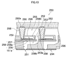
- FIG. 13 is a cross-sectional diagram showing a print head according to a third embodiment of the present invention.
- FIG. 14 is a graph showing a comparison of refill characteristics in cases in which a restrictor is present or not in relation to an ink having a viscosity of 20 cP;
- FIG. 15 is a graph showing a comparison of ejection characteristics in cases in which a restrictor is present or not in relation to an ink having a viscosity of 20 cP;
- FIG. 16 is a graph showing a comparison of refill characteristics in cases in which a restrictor is present or not in relation to ink having a viscosity of 2 cP;
- FIG. 17 is a graph showing a comparison of ejection characteristics in cases in which a restrictor is present or not in relation to ink having a viscosity of 2 cP;
- FIG. 18 is a circuit diagram showing an equivalent circuit model used for analyzing refill characteristics
- FIG. 19 is a circuit diagram showing an equivalent circuit model used for analyzing ejection characteristics
- FIG. 20 is an illustrative diagram showing values of respective elements used for analyzing refill characteristics and ejection characteristics
- FIG. 21 is a cross-sectional diagram showing a print head according to a fourth embodiment of the present invention.
- FIG. 22 is a cross-sectional diagram showing a print head according to a fifth embodiment of the present invention.
- FIG. 1 is a general schematic drawing of an inkjet recording apparatus as an image forming apparatus having a liquid ejection head according to an embodiment of the present invention.
- the inkjet recording apparatus 10 comprises: a printing unit 12 having a plurality of print heads (liquid ejection heads) 12 K, 12 C, 12 M, and 12 Y for ink colors of black (K), cyan (C), magenta (M), and yellow (Y), respectively; an ink storing and loading unit 14 for storing inks of K, C, M, and Y to be supplied to the print heads 12 K, 12 C, 12 M, and 12 Y; a paper supply unit 18 for supplying recording paper 16 ; a decurling unit 20 for removing curl in the recording paper 16 ; a suction belt conveyance unit 22 disposed facing the nozzle face (ink-droplet ejection face) of the printing unit 12 , for conveying the recording paper 16 while keeping the recording paper 16 flat; a print determination unit 24 for reading the printed result produced by the printing unit 12 ; and a paper output unit 26 for outputting image-printed recording paper (printed matter) to the exterior.
- a printing unit 12 having a plurality of print heads (liquid
- a magazine for rolled paper (continuous paper) is shown as an example of the paper supply unit 18 ; however, more magazines with paper differences such as paper width and quality may be jointly provided. Moreover, papers may be supplied with cassettes that contain cut papers loaded in layers and that are used jointly or in lieu of the magazine for rolled paper.
- a cutter 28 is provided as shown in FIG. 1 , and the roll paper is cut to a desired size by the cutter 28 .
- the cutter 28 has a stationary blade 28 A, of which length is not less than the width of the conveyor pathway of the recording paper 16 , and a round blade 28 B, which moves along the stationary blade 28 A.
- the stationary blade 28 A is disposed on the reverse side of the printed surface of the recording paper 16
- the round blade 28 B is disposed on the printed surface side across the conveyance path.
- the cutter 28 is not required.
- an information recording medium such as a bar code and a wireless tag containing information about the type of paper is attached to the magazine, and by reading the information contained in the information recording medium with a predetermined reading device, the type of paper to be used is automatically determined, and ink-droplet ejection is controlled so that the ink-droplets are ejected in an appropriate manner in accordance with the type of paper.
- the recording paper 16 delivered from the paper supply unit 18 retains curl due to having been loaded in the magazine.
- heat is applied to the recording paper 16 in the decurling unit 20 by a heating drum 30 in the direction opposite from the curl direction in the magazine.
- the heating temperature at this time is preferably controlled so that the recording paper 16 has a curl in which the surface on which the print is to be made is slightly round outward.
- the decurled and cut recording paper 16 is delivered to the suction belt conveyance unit 22 .
- the suction belt conveyance unit 22 has a configuration in which an endless belt 33 is set around rollers 31 and 32 so that the portion of the endless belt 33 facing at least the nozzle face of the printing unit 12 and the sensor face of the print determination unit 24 forms a horizontal plane (flat plane).
- the belt 33 has a width that is greater than the width of the recording paper 16 , and a plurality of suction apertures (not shown) are formed on the belt surface.
- a suction chamber 34 is disposed in a position facing the sensor surface of the print determination unit 24 and the nozzle surface of the printing unit 12 on the interior side of the belt 33 , which is set around the rollers 31 and 32 , as shown in FIG. 1 .
- the suction chamber 34 provides suction with a fan 35 to generate a negative pressure, and the recording paper 16 on the belt 33 is held by suction.
- the belt 33 is driven in the clockwise direction in FIG. 1 by the motive force of a motor 88 (not shown) being transmitted to at least one of the rollers 31 and 32 , which the belt 33 is set around, and the recording paper 16 held on the belt 33 is conveyed from left to right in FIG. 1 .
- a belt-cleaning unit 36 is disposed in a predetermined position (a suitable position outside the printing area) on the exterior side of the belt 33 .
- the details of the configuration of the belt-cleaning unit 36 are not shown, examples thereof include a configuration in which the belt 33 is nipped with cleaning rollers such as a brush roller and a water absorbent roller, an air blow configuration in which clean air is blown onto the belt 33 , or a combination of these.
- the inkjet recording apparatus 10 can comprise a roller nip conveyance mechanism, in which the recording paper 16 is pinched and conveyed with nip rollers, instead of the suction belt conveyance unit 22 .
- a roller nip conveyance mechanism in which the recording paper 16 is pinched and conveyed with nip rollers, instead of the suction belt conveyance unit 22 .
- the suction belt conveyance in which nothing comes into contact with the image surface in the printing area is preferable.
- a heating fan 40 is disposed on the upstream side of the printing unit 12 in the conveyance pathway formed by the suction belt conveyance unit 22 .
- the heating fan 40 blows heated air onto the recording paper 16 to heat the recording paper 16 immediately before printing so that the ink deposited on the recording paper 16 dries more easily.
- the printing unit 12 is a so-called “full line head” in which a line head having a length corresponding to the maximum paper width is arranged in a direction (main scanning direction) that is perpendicular to the paper conveyance direction (sub-scanning direction) (see FIG. 2 ).
- the print heads 12 K, 12 C, 12 M and 12 Y are constituted by line heads in which a plurality of ink ejection ports (nozzles) are arranged through a length exceeding at least one edge of the maximum size recording paper 16 intended for use with the inkjet recording apparatus 10 .
- the print heads 12 K, 12 C, 12 M, and 12 Y corresponding to respective ink colors are disposed in the order, black (K), cyan (C), magenta (M) and yellow (Y), from the upstream side (left-hand side in FIG. 1 ), following the direction of conveyance of the recording paper 16 (the paper conveyance direction).
- a color print can be formed on the recording paper 16 by ejecting the inks from the print heads 12 K, 12 C, 12 M, and 12 Y, respectively, onto the recording paper 16 while conveying the recording paper 16 .
- the printing unit 12 in which the full-line heads covering the entire width of the paper are thus provided for the respective ink colors, can record an image over the entire surface of the recording paper 16 by performing the action of moving the recording paper 16 and the printing unit 12 relatively to each other in the paper conveyance direction (sub-scanning direction) just once (in other words, by means of a single sub-scan). Higher-speed printing is thereby made possible and productivity can be improved in comparison with a shuttle type head configuration in which a recording head moves reciprocally in the direction (main scanning direction) which is perpendicular to the paper conveyance direction (sub-scanning direction).
- main scanning direction and “sub-scanning direction” are used in the following senses. More specifically, in a full-line head comprising rows of nozzles that have a length corresponding to the entire width of the recording paper, “main scanning” is defined as printing one line (a line formed of a row of dots, or a line formed of a plurality of rows of dots) in the breadthways direction of the recording paper (the direction perpendicular to the conveyance direction of the recording paper) by driving the nozzles in one of the following ways: (1) simultaneously driving all the nozzles; (2) sequentially driving the nozzles from one side toward the other; and (3) dividing the nozzles into blocks and sequentially driving the blocks of the nozzles from one side toward the other.
- the direction indicated by one line recorded by a main scanning action (the lengthwise direction of the band-shaped region thus recorded) is called the “main scanning direction”.
- sub-scanning is defined as to repeatedly perform printing of one line (a line formed of a row of dots, or a line formed of a plurality of rows of dots) formed by the main scanning, while moving the full-line head and the recording paper relatively to each other.
- the direction in which sub-scanning is performed is called the sub-scanning direction. Consequently, the conveyance direction of the reference point is the sub-scanning direction and the direction perpendicular to same is called the main scanning direction.
- the combinations of the ink colors and the number of colors are not limited to these, and light and/or dark inks can be added as required.
- a configuration is possible in which print heads for ejecting light-colored inks such as light cyan and light magenta are added.
- the ink storing and loading unit 14 has tanks for storing inks of the colors corresponding to the respective print heads 12 K, 12 C, 12 M and 12 Y, and each tank is connected to a respective print head 12 K, 12 C, 12 M, and 12 Y, via a tube channel (not shown).
- the ink storing and loading unit 14 also comprises a notifying device (display device, alarm generating device, or the like) for generating a notification if the remaining amount of ink has become low, as well as having a mechanism for preventing incorrect loading of the wrong colored ink.
- the print determination unit 24 has an image sensor for capturing an image of the ink-droplet deposition result of the printing unit 12 , and functions as a device to check for ejection defects such as clogs of the nozzles in the printing unit 12 from the ink-droplet deposition results evaluated by the image sensor (line sensor).
- the print determination unit 24 of the present embodiment is configured with at least a line sensor having rows of photoelectric conversion elements with a width that is greater than the ink-droplet ejection width (image recording width) of the print heads 12 K, 12 C, 12 M, and 12 Y.
- This line sensor has a color separation line CCD sensor including a red (R) sensor row composed of photoelectric conversion elements (pixels) arranged in a line provided with an R filter, a green (G) sensor row with a G filter, and a blue (B) sensor row with a B filter.
- R red
- G green
- B blue
- the print determination unit 24 reads a test pattern image printed by the print heads 12 K, 12 C, 12 M, and 12 Y for the respective colors, and determines the ejection of each head. This ejection determination includes the presence of ejection, measurement of the dot size, and measurement of the dot deposition position.
- a post-drying unit 42 is disposed following the print determination unit 24 .
- the post-drying unit 42 is a device to dry the printed image surface, and includes a heating fan, for example. It is preferable to avoid contact with the printed surface until the printed ink dries, and a device that blows heated air onto the printed surface is preferable.
- a heating/pressurizing unit 44 is disposed following the post-drying unit 42 .
- the heating/pressurizing unit 44 is a device to control the glossiness of the image surface, and the image surface is pressed with a pressure roller 45 having a predetermined uneven surface shape while the image surface is heated, and the uneven shape is transferred to the image surface.
- the printed matter generated in this manner is outputted from the paper output unit 26 .
- the target print i.e., the result of printing the target image
- the test print are preferably outputted separately.
- a sorting device (not shown) is provided for switching the outputting pathways in order to sort the printed matter with the target print and the printed matter with the test print, and to send them to paper output units 26 A and 26 B, respectively.
- the test print portion is cut and separated by a cutter (second cutter) 48 .
- the cutter 48 is disposed directly in front of the paper output unit 26 , and is used for cutting the test print portion from the target print portion when a test print has been performed in the blank portion of the target print.
- the structure of the cutter 48 is the same as the first cutter 28 described above, and has a stationary blade 48 A and a round blade 48 B.
- the paper output unit 26 A for the target prints is provided with a sorter for collecting prints according to print orders.
- FIG. 3 shows a plan view perspective diagram of the print head 50 .
- the print head 50 achieves a high density arrangement of nozzles 51 by using a two-dimensional staggered matrix array of pressure chamber units 54 , respectively constituted by a nozzle for ejecting ink as ink droplets, a pressure chamber 52 for applying pressure to the ink in order to eject ink, and an ink supply port 53 for supplying ink to the pressure chamber 52 from a common flow channel (not shown in FIG. 3 ).
- nozzle arrangement in a print head 50 of this kind there is no particular limitation on the size of the nozzle arrangement in a print head 50 of this kind, but as one example, 2400 npi can be achieved by arranging nozzles 51 in 48 lateral rows (21 mm) and 600 vertical columns (305 mm).
- the pressure chambers 52 respectively have an approximately square planar shape when viewed from above, but the planar shape of the pressure chambers 52 is not limited to a square shape.
- a nozzle 51 is formed at one end of the diagonal of each pressure chamber 52 , and an ink supply port 53 is provided at the other end thereof.
- FIG. 4 is a plan view perspective diagram showing another example of the structure of a print head.
- one long full line head may be constituted by combining a plurality of short heads 50 ′ arranged in a two-dimensional staggered array, in such a manner that the combined length of this plurality of short heads 50 ′ corresponds to the full width of the print medium.
- FIG. 5 is a schematic drawing showing the configuration of the ink supply system in the inkjet recording apparatus 10 .
- the ink tank 60 is a base tank that supplies ink to the print head 50 and is set in the ink storing and loading unit 14 described with reference to FIG. 1 .
- the aspects of the ink tank 60 include a refillable type and a cartridge type: when the remaining amount of ink is low, the ink tank 60 of the refillable type is filled with ink through a filling port (not shown) and the ink tank 60 of the cartridge type is replaced with a new one.
- the cartridge type is suitable, and it is preferable to represent the ink type information with a bar code or the like on the cartridge, and to perform ejection control in accordance with the ink type.
- the ink tank 60 in FIG. 5 is equivalent to the ink storing and loading unit 14 in FIG. 1 described above.
- a filter 62 for removing foreign matters and bubbles is disposed at an intermediate position of the tube channel which connects the ink tank 60 with the print head 50 as shown in FIG. 5 .
- the filter mesh size in the filter 62 is preferably equivalent to or less than the diameter of the nozzle of the print head 50 and commonly about 20 ⁇ m.
- the sub-tank has a damper function for preventing variation in the internal pressure of the head and a function for improving refilling of the print head 50 .
- the inkjet recording apparatus 10 is also provided with a cap 64 as a device to prevent the nozzles from drying out or to prevent an increase in the ink viscosity in the vicinity of the nozzles 51 , and a cleaning blade 66 as a device to clean the nozzle face 50 A.
- a maintenance unit including the cap 64 and the cleaning blade 66 can be relatively moved with respect to the print head 50 by a movement mechanism (not shown), and is moved from a predetermined holding position to a maintenance position below the print head 50 as required.
- the cap 64 is displaced upwards and downwards in a relative fashion with respect to the print head 50 by an elevator mechanism (not shown).
- the elevator mechanism raises the cap 64 to a predetermined elevated position so as to come into close contact with the print head 50 , and the nozzle region of the nozzle face 50 A is thereby covered by the cap 64 .
- the cleaning blade 66 is composed of rubber or another elastic member, and can slide on the ink ejection surface (nozzle surface 50 A) of the print head 50 by means of a blade movement mechanism (not shown). If there are ink droplets or foreign matter adhering to the nozzle surface 50 A, then the nozzle surface 50 A is wiped by causing the cleaning blade 66 to slide over the nozzle surface 50 A, thereby cleaning same.
- the cap 64 is placed on the print head 50 , ink (ink in which bubbles have become intermixed) inside the pressure chambers 52 is removed by suction with a suction pump 67 , and the ink removed by suction is sent to a collection tank 68 .
- This suction operation is also carried out in order to suction and remove degraded ink which has hardened due to increasing in viscosity when ink is loaded into the head for the first time, and when the head starts to be used after having been out of use for a long period of time.
- a “preliminary ejection” is carried out, whereby the pressure generating devices are operated and the ink in the vicinity of the nozzles, which is of raised viscosity, is ejected toward the ink receptacle.
- a preliminary ejection is also carried out in order to prevent infiltration of foreign matter inside the nozzles 51 due to the rubbing action of the wiper.
- the preliminary ejection is also referred to as “dummy ejection”, “purge”, “liquid ejection”, and so on.
- ink can no longer be ejected from the nozzles even if the laminated pressure generating devices are operated.
- a cap 64 is placed on the nozzle surface 50 A of the print head 50 , and the ink containing air bubbles or the ink of increased viscosity inside the pressure chambers 52 is suctioned by a pump 67 .
- the cap 64 shown in FIG. 5 functions as a suctioning device and it may also function as an ink receptacle for preliminary ejection.
- the inside of the cap 64 is divided by means of partitions into a plurality of areas corresponding to the nozzle rows, thereby achieving a composition in which suction can be performed selectively in each of the demarcated areas, by means of a selector, or the like.
- FIG. 6 is a principal block diagram showing the system configuration of the inkjet recording apparatus 10 .
- the inkjet recording apparatus 10 comprises a communication interface 70 , a system controller 72 , an image memory 74 , a motor driver 76 , a heater driver 78 , a print controller 80 , an image buffer memory 82 , a head driver 84 , and the like.
- the communication interface 70 is an interface unit for receiving image data sent from a host computer 86 .
- a serial interface such as USB, IEEE1394, Ethernet, wireless network, or a parallel interface such as a Centronics interface may be used as the communication interface 70 .
- a buffer memory (not shown) may be mounted in this portion in order to increase the communication speed.
- the image data sent from the host computer 86 is received by the inkjet recording apparatus 10 through the communication interface 70 , and is temporarily stored in the image memory 74 .
- the image memory 74 is a storage device for temporarily storing images inputted through the communication interface 70 , and data is written and read to and from the image memory 74 through the system controller 72 .
- the image memory 74 is not limited to a memory composed of semiconductor elements, and a hard disk drive or another magnetic medium may be used.
- the system controller 72 is a control unit for controlling the various sections, such as the communications interface 70 , the image memory 74 , the motor driver 76 , the heater driver 78 , and the like.
- the system controller 72 is constituted by a central processing unit (CPU) and peripheral circuits thereof, and the like, and in addition to controlling communications with the host computer 86 and controlling reading and writing from and to the image memory 74 , or the like, it also generates a control signal for controlling the motor 88 of the conveyance system and the heater 89 .
- CPU central processing unit
- the motor driver (drive circuit) 76 drives the motor 88 in accordance with commands from the system controller 72 .
- the heater driver (drive circuit) 78 drives the heater 89 of the post-drying unit 42 or the like in accordance with commands from the system controller 72 .
- the print controller 80 has a signal processing function for performing various tasks, compensations, and other types of processing for generating print control signals from the image data stored in the image memory 74 in accordance with commands from the system controller 72 so as to supply the generated print control signal (print data) to the head driver 84 .
- Prescribed signal processing is carried out in the print controller 80 , and the ejection amount and the ejection timing of the ink droplets from the respective print heads 50 are controlled via the head driver 84 , on the basis of the print data. By this means, prescribed dot size and dot positions can be achieved.
- the print controller 80 is provided with the image buffer memory 82 ; and image data, parameters, and other data are temporarily stored in the image buffer memory 82 when image data is processed in the print controller 80 .
- the aspect shown in FIG. 6 is one in which the image buffer memory 82 accompanies the print controller 80 ; however, the image memory 74 may also serve as the image buffer memory 82 . Also possible is an aspect in which the print controller 80 and the system controller 72 are integrated to form a single processor.
- the head driver 84 drives the pressure generating devices of the print heads 50 of the respective colors KCMY according to print data supplied by the print controller 80 .
- the head driver 84 can be provided with a feedback control system for maintaining constant drive conditions for the print heads.
- the print determination unit 24 is a block that includes the line sensor (not shown) as described above with reference to FIG. 1 , reads the image printed on the recording paper 16 , determines the print conditions (presence of the ejection, variation in the dot formation, and the like) by performing desired signal processing, or the like, and provides the determination results of the print conditions to the print controller 80 .
- the print controller 80 makes various corrections with respect to the print head 50 on the basis of information obtained from the print determination unit 24 .
- a liquid ejection head (print head 50 ) that can drive ejection at high frequency and eject ink of high viscosity even if the nozzles, the ink supply system, and the wiring which supplies the drive signals are arranged at high density.
- a high-density arrangement of nozzles 51 is obtained (for example, 2400 npi) by arranging pressure chambers 52 (nozzles 51 ) in the form of a two-dimensional matrix, as shown in FIG. 3 for example.
- a common liquid chamber supplying ink to the pressure chambers 52 is disposed above the diaphragm, the ink is supplied directly from this common liquid chamber to the pressure chambers 52 for prioritizing ink refilling characteristics, and then a tubing which causes flow resistance is eliminated, so that the ink supply system is integrated to a high degree.
- the electrical wiring which supplies drive signals to the electrodes (individual electrodes) of the pressure generating devices that deform the pressure chambers 52 is connected to upper wiring, such as a flexible cable, so as to rise upwards vertically from each individual electrode through the common liquid chamber.
- FIG. 7 shows an oblique perspective view simplified a part of a print head 50 formed in high density, in this way.
- diaphragm 56 which form the upper surface of pressure chambers 52 are disposed on the upper side of pressure chambers 52 each having a nozzle 51 and an ink supply port 53 , and piezoelectric elements 58 (piezoelectric actuators) as the pressure generating devices constituted by a piezoelectric body, such as a piezo element, which is sandwiched between upper and lower electrodes, are disposed in a position on the diaphragm 56 corresponding to the respective pressure chambers 52 .
- An individual electrode 57 is provided on the upper surface of each piezoelectric element 58 .
- Electrode pads 59 as electrode connecting sections are extracted to the outer sides from the end faces of each individual electrode 57 , and then electrical wires 90 are formed on those electrode pads 59 so as to rise up in a substantially perpendicular direction to a plane including the piezoelectric elements 58 (pressure generating devices).
- a multi-layer flexible cable 92 is provided above the electrical wires 90 which rise up in a substantially perpendicular direction to the plane including the piezoelectric elements 58 , and therefore the drive signals are supplied from the head driver 84 to the individual electrodes 57 of the piezoelectric elements 58 via those wires.
- the space in which the column-shaped electrical wires 90 are erected between the diaphragm 56 and the flexible cables 92 is formed into a common liquid chamber 55 for supplying ink to the respective pressure chambers 52 via the respective ink supply ports 53 .
- the common liquid chamber 55 shown in FIG. 7 is one large space formed throughout the whole region where the pressure chambers 52 are formed so as to supply ink to all of the pressure chambers 52 shown in FIG. 3 .
- the common liquid chamber 55 is not limited to those formed in one space, and may be formed by dividing up the space into several regions.
- Each of the electrical wires 90 rises up perpendicularly like a column on top of the electrode pads 59 provided connecting to the individual electrodes 57 at each pressure chamber 52 , and supports the flexible cable 92 from below so as to create a space which forms the common liquid chamber 55 .
- the electrical wires 90 which rise up like columns may also be called “electric columns”, due to that shape.
- the electrical wires 90 (electrical columns) are formed so as to pass through the common liquid chamber 55 .
- the electrical wires 90 shown in FIG. 7 are formed independently with respect to each of the piezoelectric elements 58 (or the individual electrodes 57 thereof), in a one-to-one correspondence.
- the wiring to the common electrode (diaphragm 56 ) may also be formed as electrical wires 90 , in addition to that connected to the individual electrodes 57 .
- Nozzles 51 are formed in the bottom surfaces as shown in FIG. 7 , and ink supply ports 53 are provided on the upper surfaces in corner sections which are symmetrical with respect to the nozzles 51 .
- the ink supply ports 53 are pierced through the diaphragm 56 , and then the upper-positioned common liquid chamber 55 and the pressure chambers 52 are connected directly by means of the ink supply ports 53 . Consequently, it is possible to form a direct fluid connection between the common liquid chamber 55 and each of the pressure chambers 52 .
- the diaphragm 56 is formed in a single plate which is common to all of the pressure chambers 52 .
- Piezoelectric elements 58 deforming the pressure chambers 52 are disposed on the diaphragm 56 in positions corresponding to the respective pressure chambers 52 .
- Electrodes (a common electrode and an individual electrode) for driving the piezoelectric elements 58 by applying a voltage thereto are formed on the upper and lower surfaces of respective piezoelectric elements 58 , thereby sandwiching the piezoelectric elements 58 .
- the diaphragm 56 may be formed as a thin conductive film made of stainless steel, or the like, in such a manner that the diaphragm 56 may also serve as a common electrode.
- individual electrodes 57 driving the piezoelectric elements 58 independently are provided on the upper surface of each of the piezoelectric elements 58 .
- the electrode pads 59 are formed leading from the respective individual electrodes 57 , and the electrical wires 90 (electrical columns) which pass through the common liquid chamber 55 are formed rising up perpendicularly from the electrode pads 59 .
- the method of manufacturing the electrical wires 90 (electrical columns) is described hereinafter, but in this manufacturing process, the electrical wires 90 are formed in a tapered shape, as shown in FIG. 7 .
- a multi-layer flexible cable 92 is formed on top of the column-shaped electrical wires 90 .
- the multi-layer flexible cable 92 is supported on the pillars formed by the electrical wires 90 .
- a space is formed as the common liquid chamber 55 by taking the diaphragm 56 as the base, and the multi-layer flexible cable 92 as the ceiling.
- the respective individual electrodes 57 are each connected independently to the respective electrical wires 90 , in such a manner that drive signals are supplied respectively to the individual electrodes 57 , thereby driving the piezoelectric elements 58 .
- the common liquid chamber 55 is filled with ink
- the surface, which makes contact with the ink, of the diaphragm 56 as the common electrode, the individual electrodes 57 , the electrical wires 90 , and the multi-layer flexible cable 92 are covered respectively with an insulating protective film.
- the pressure chambers 52 have an approximately square planner shape of 300 ⁇ m ⁇ 300 ⁇ m (the corners thereof being curved in order to prevent stagnation points in the ink flow), and the height of the pressure chambers 52 is 150 ⁇ m.
- each of the diaphragm 56 and the piezoelectric elements 58 has a thickness of 10 ⁇ m, and the electrical wires 90 (electrical columns) have a diameter of 100 ⁇ m at the connection with the electrode pads 59 , and a height of 500 ⁇ m.
- FIG. 8 shows a part of pressure chambers 52 of this kind, in an enlarged plan view perspective diagram.
- each of the pressure chambers 52 has a substantially square shape, and the nozzle 51 and the ink supply port 53 are formed at respective corners of a diagonal of the respective pressure chamber 52 .
- the electrode pads 59 are extracted adjacently to the nozzles 51 , and the electrical wires (electrical column) 90 are formed on top of the electrode pads 59 .
- FIG. 9 is a cross-sectional diagram along line 9 - 9 in FIG. 8 .
- the print head 50 is formed by laminating together a plurality of thin plates, or the like.
- a flow channel plate 96 formed with the pressure chambers 52 , the ink supply ports 53 , and nozzle flow channels 51 a linking the pressure chambers 52 and the nozzles 51 is layered onto a nozzle plate 94 formed with nozzles 51 .
- the flow channel plate 96 is depicted as a single plate, but in practice, the flow channel plate 96 may also be formed by laminating together a plurality of plates.
- the diaphragm 56 forming the ceiling faces of the pressure chambers 52 is laminated onto the flow channel plate 96 .
- the diaphragm 56 also serves as a common electrode for driving the piezoelectric elements 58 , as described below in conjunction with the individual electrodes 57 .
- opening sections corresponding to the ink supply ports 53 of the pressure chambers 52 are provided in the diaphragm 56 , thereby providing direct connection between the pressure chambers 52 and the common liquid chamber 55 formed on the upper side of the diaphragm 56 .
- a piezoelectric bodies 58 a are formed on the diaphragm 56 (common electrodes) in regions corresponding to approximately the whole upper surfaces of the pressure chambers 52 , and the individual electrodes 57 are formed on the upper surfaces of the piezoelectric bodies 58 a .
- the piezoelectric bodies 58 a sandwiched between a lower common electrode (diaphragm 56 ) and upper individual electrodes 57 in this way reduce the volume of the pressure chambers 52 by deforming when a voltage is applied via the common electrodes 56 and the individual electrodes 57 , thereby constituting a piezoelectric elements 58 (piezoelectric actuators) which cause ink to be ejected from the nozzles 51 .
- the electrode pads 59 as electrode connecting sections extracted to the outside are formed on the ends of the individual electrodes 57 adjacent to the nozzles 51 .
- a column-shaped electrical wires 90 (electrical columns) are formed perpendicularly on tops of the electrode pads 59 so as to pass through the common liquid chamber 55 .
- a multi-layer flexible cable 92 is formed on tops of the electrical wires 90 , and wires (not shown) formed in the multi-layer flexible cable 92 are connected via the electrodes pads 59 to each the electrical wires 90 , in such a manner that drive signals for driving the piezoelectric elements 58 can be supplied via the respective electrical wires 90 .
- the space in which the column-shaped electrical wires 90 (electrical column) are erected between the diaphragm 56 and the multi-layer flexible cable 92 forms a common liquid chamber 55 which accumulate ink supplying to the pressure chambers 52 . Since this space is filled with ink, the surface portions which make contact with the ink of the diaphragm 56 , the individual electrodes 57 , the piezoelectric bodies 58 a , the electrical wires 90 , and the multi-layer flexible cable 92 are covered with an insulating/protective film 98 .
- the common liquid chamber 55 which is conventionally disposed on the same sides of pressure chambers 52 with respect to the diaphragm 56 is transferred to the upper side of the diaphragm 56 , in other words, the common liquid chamber 55 is disposed on the opposite sides to the pressure chambers 52 . Therefore, in contrast to the prior art, no piping or the like is necessary for supplying the ink from the common liquid chamber 55 to the pressure chambers 52 . In addition, since the size of the common liquid chamber 55 can be increased, the ink can be supplied reliably. Therefore, it is possible to achieve high nozzle density while also enabling driving at high frequency even when the nozzles are arranged at high density.
- the wiring to the individual electrodes 57 of the respective piezoelectric elements 58 rises up perpendicularly from the electrode pads 59 of the individual electrodes 57 , it is possible to increase the density of the wiring used to supply drive signals to the piezoelectric elements 58 .
- the common liquid chamber 55 is positioned on the upper side of the diaphragm 56 in such a manner that the common liquid chamber 55 and pressure chambers 52 are connected by means of the direct ink supply ports 53 , it is possible to provide a direct fluid connection between the common liquid chamber 55 and the pressure chambers 52 . Additionally, since the common liquid chamber 55 is positioned on the upper side of the diaphragm 56 , it is possible to reduce the length of the nozzle flow channels 51 a from the pressure chambers 52 to the nozzles 51 , in comparison with the prior art.
- the nozzles 51 are formed to a high density, it is possible to eject ink of high viscosity (for example, approximately 20 cp to 50 cp), while the print head 50 with a flow channel structure capable of swift refilling after ejection is achieved.
- high viscosity for example, approximately 20 cp to 50 cp
- FIGS. 10A to 10D show steps for manufacturing the print head 50 described above.
- the pressure chambers 52 are formed as shown in FIG. 10A .
- the method of forming the pressure chambers 52 is not limited in particular, but as one example, stainless steel plates etched to create open spaces which are to form pressure chambers are laminated together, or alternatively, a silicon plate is etched to form a flow channel plate 96 having spaces for forming pressure chambers 52 .
- a nozzle plate 94 having nozzle 51 (which is made of polyimide, for example) is bonded onto the flow channel plate 96 formed with a space which is to create the pressure chamber 52 .
- a diaphragm 56 is bonded onto the flow channel plate 96 formed with the space which is to create the pressure chamber 52 .
- the diaphragm 56 also serves as a common electrode.
- An aperture is provided in the diaphragm 56 in a position corresponding to the ink supply port 53 of the pressure chamber 52 .
- a thin film-shaped piezoelectric body 58 a is formed by AD (aerosol deposition) or sputtering on the upper side of the diaphragm 56 , in a section corresponding to the respective pressure chamber 52 .
- the piezoelectric body 58 a may also be formed by grinding a bulk piezoelectric body.
- the diaphragm 56 and the piezoelectric body 58 a are formed to a thickness of approximately 10 ⁇ m, for example.
- a common liquid chamber 55 is formed as shown in FIG. 10C .
- a part of the individual electrode 57 (for example, the end adjacent to the nozzle 51 ) is extracted to the outer side, thereby forming an electrode pad 59 for making a wiring connection.
- the front end of the electrical wire 90 is connected to the electrode pad 59 by means of a solder 90 a provided on the end of the electrical wire 90 .
- the method of fabricating the electrical wire 90 (electrical column) is described below.
- the piezoelectric element 58 is constituted by piezoelectric body 58 a which is sandwiched between a diaphragm 56 (common electrode) and an individual electrode 57 on the pressure chamber 52 , and the common liquid chamber 55 is formed by bonding the wiring plate 91 formed with the electrical wire 90 (electrical column) onto a plate which is formed with the piezoelectric element 58 . Then, although this is not shown in the diagram, an insulating/protective film is formed onto the sections which make contact with the ink in the common liquid chamber 55 .
- a multi-layer flexible cable 92 is bonded on top of the wiring plate 91 , thereby forming the print head 50 .
- the electrical wire 90 and the multi-layer flexible cable 92 are connected together by means of the solder 90 a provided on the other end of the electrical wire 90 .
- the multi-layer flexible cable 92 is formed in at least four layers or more.
- FIGS. 11A to 11E show the steps for manufacturing the electrical wires 90 .
- a copper layer 93 having a thickness of approximately 500 ⁇ m is formed onto an insulating substrate as a wiring plate 91 for forming the electrical wires 90 (electrical columns).
- the copper layer 93 having a thickness of approximately 500 ⁇ m is cut by etching in order to form column-shaped electrical wire 90 (electrical columns).
- the electrical wires 90 are formed so as to have a diameter d 1 at the front end section (namely, the section which is subsequently to be connected to an electrode pad 59 ) of approximately 100 ⁇ m, and a height d 2 of approximately 500 ⁇ m, which is equal to the thickness of the copper layer 93 .
- an insulating/protective film 98 is coated onto the side faces of the column shapes of the electrical wires 90 .
- the electrical wires 90 pass through the common liquid chamber 55 , it is possible to prevent the electrical wires 90 from making contact with the ink at all times by the insulating/protective film 98 .
- the wiring plate 91 is processed from the under side, and holes 91 a for connecting with the multi-layer flexible cable 92 are opened in the sections where the electrical wires 90 are located.
- the holes 91 a may be formed previously in the wiring plate 91 before forming a copper layer 93 on the wiring plate 91 .
- each of the electrical wires 90 is formed on the wiring plate 91 by introducing the solder 90 a to the upper and lower end section of the respective electrical wire 90 .
- the resulting structure is inverted vertically and is bonded to the flow channel plate 96 formed with pressure chambers 52 and the like, thereby forming the print head 50 as shown in FIGS. 10A to 10D .
- the electrical wires 90 may be separated individually from the wiring plate 91 so as to bond the separated electrical wires 90 to the electrode pads 59 of the individual flow channel plates 96 .
- installing the electrical wires 90 individually requires significant labor, it is not necessary to set accurately the position at which the electrical wires 90 are formed on the wiring plate 91 .
- FIG. 12 shows a cross-sectional diagram of a print head according to the second embodiment of the present invention.
- FIG. 12 is a cross-sectional diagram similar to FIG. 9 .
- a common liquid chamber 155 is formed at the opposite side to the pressure chamber 152 with respect to the diaphragm 156 .
- a flow channel plate 196 which forms with the pressure chambers 152 and the like, is disposed on a nozzle plate 194 including the nozzles 151 , and the diaphragm 156 is placed on the flow channel plate 196 .
- the piezoelectric elements 158 are formed on the diaphragm 156 , and comprise the diaphragm 156 as a common electrode, the piezoelectric bodies 158 a , and the individual electrodes 157 .
- the electrical wires 190 (electrical columns) are formed in a substantially perpendicular upward direction to the electrode pads 159 extracted from the individual electrodes 157 .
- a multi-layer flexible cable 192 is formed on the electrical wires 190 , and the space between the diaphragm 156 and the multi-layer flexible cable 192 forms common liquid chambers 155 .
- the electrical wires 190 are formed so as to pass through the common liquid chambers 155 .
- the print head 150 according to the present embodiment has an approximately similar composition to the print head 50 according to the first embodiment described above.
- gaps 158 b for the operation of actuators are provided on top of the piezoelectric elements 158 constituted by the diaphragm 156 (common electrode), the piezoelectric bodies 158 a , and the individual electrodes 157 .
- the gaps 158 b are formed by respectively providing frames 158 c around the piezoelectric elements 158 so as to completely cover the piezoelectric bodies 158 a and the individual electrodes 157 .
- an insulating/protective film 198 is formed on the surface of the frames 158 c .
- the frames 158 c may be formed by means of the insulating/protective film 198 only.
- the gaps 158 b are provided above the piezoelectric elements 158 , it is possible to decrease the resistance exerted by driving the piezoelectric elements 158 . Therefore, since the piezoelectric elements 158 can be operated more readily, it is possible to improve the driving efficiency of the piezoelectric elements 158 .
- FIG. 13 shows a cross-sectional diagram of a print head according to the third embodiment of the present invention, as similar to FIG. 12 .
- the print head 250 according to the present embodiment has an approximately similar composition to the print head 150 according to the second embodiment shown in FIG. 12 .
- the common liquid chambers 255 are positioned on the upper side of the diaphragm 256 , and the electrical wires 290 are erected perpendicularly so as to pass through the common liquid chambers 255 .
- the gaps 258 b are provided in order to facilitate the operation of the piezoelectric bodies 258 .
- ink reflux preventing restrictors 253 a having a narrow diameter are provided in portions of the ink supply ports 253 which supplies ink from the common liquid chambers 255 to the pressure chambers 252 .
- the restrictors 253 a are formed by reducing the diameter of apertures which are formed at the side of the ink supply ports 253 in the diaphragm 256 .
- FIG. 14 is a graph showing refilling characteristics in cases in which the restrictor 253 a is present or not, when ejecting 2 pl of the ink having a viscosity of 20 cP. Incidentally, the specific method of analyzing the refill characteristics is described below.
- the graph A shows a characteristic curve when the restrictor 253 a is not present
- the graph B shows a characteristic curve when the restrictor 253 a is present.
- the horizontal axis indicates the time ( ⁇ sec)
- the vertical axis indicates a meniscus volume (pl).
- the meniscus volume has become zero
- the refill is completed.
- the meniscus volume is positive (>0)
- the meniscus surface is stocked out the initial position thereof.
- the refill time is 60 ⁇ sec.
- the refill time becomes 30 ⁇ sec, which is half the time achieved when the restrictor 253 a is present.
- FIG. 15 is a graph showing ejection characteristics in cases in which the restrictor 253 a is present or not, when ejecting 2 pl of the ink having a viscosity of 20 cP. Incidentally, the specific method of analyzing the ejection characteristics is described hereinafter.
- the graph A shows a characteristic curve when the restrictor 253 a is not present
- the graph B shows a characteristic curve when the restrictor 253 a is present.
- the horizontal axis indicates the time ( ⁇ sec)
- the vertical axis indicates the particle speed in nozzle (m/sec).
- This ejection characteristic can be explained as following.
- the ink flow toward the nozzle side is a flow in the ejecting direction
- the ink flow toward the supply side is a flow in the reflux direction.
- a ratio between the ink volumes moving toward the nozzle side and the supply side namely (nozzle side)/(supply side+nozzle side) is equal to 0.54 when the restrictor 253 a is present, and the (nozzle side)/(supply side+nozzle side) is equal to 0.28 when the restrictor 253 a is not present. Therefore, efficiency is twice as good when the restrictor 253 a is present, compared to when the restrictor 253 a is present.
- the attenuation rate is 1.32 when the restrictor 253 a is present, the attenuation rate is 1.79 when the restrictor 253 a is not present. This means that the attenuation rate is 1.4 greater when the restrictor 253 a is present. Consequently, since these two effects can be thought to cancel each other out, it is considered that there is no great difference between the ejection characteristics when the restrictor 253 a is present or not.
- FIG. 16 a graph showing refill characteristics in cases in which the restrictor 253 a is present or not, when ejecting 2 pl of ink having a viscosity of 2 cP.
- FIG. 17 a graph showing the ejection characteristics in the same conditions.
- the meniscus surface vibrates greatly, regardless of whether or not the restrictor 253 a is present. Therefore, in order to shorten the refill time, it is essential to suppress the vibration of the meniscus surface, irrespective of the presence or absence of the restrictor 253 a.
- R is the combined resistance of the nozzle and the supply restrictor
- M is the combined inertance of the nozzle and supply restrictor
- C is the compliance of the nozzle meniscus, which is a value varying according to the shape of the meniscus (the refill state). Taking the distance from the upper surface of the nozzle to the lowest part of the meniscus to be “y”; the radius of the nozzle to be “r n ”; and the surface tension of the ink to be “ ⁇ ”, the compliance C is shown as a following equation (1):
- FIG. 19 an equivalent circuit model shown in FIG. 19 is used for analyzing the ejection characteristics.
- C p is the compliance of the piezo actuator
- C c is the compliance of the pressure chamber
- R n is the nozzle resistance
- R s is the supply restrictor resistance
- M n is the nozzle inertance
- M s is the supply restrictor inertance
- V is the pressure generated by the piezo actuator.
- FIG. 20 shows actual values of the respective elements used for analyzing the refill characteristics and the ejection characteristics.
- the term “nozzle side” includes the nozzle and a connection path from the pressure chamber to the nozzle
- the term “supply side” includes the supply restrictor and a connection path to the common liquid chamber.
- the ink supply port 53 or 153 which connects the common liquid chamber 55 or 155 with the pressure chamber 52 or 152 , has a uniform diameter, and no particular restrictor is provided therein.
- the reflux is suppressed by the mass of the actual ink in a section of the ink supply port 53 or 153 between the common liquid chamber 55 or 155 and the pressure chamber 52 or 152 .
- the restrictor 253 a having a narrow diameter is provided in order to prevent a reflux more effectively.
- the remaining composition except for the restrictor 253 a is the same as the composition in the first and second embodiments described above, and hence the same last two digits are used for the reference numerals of the respective constituent elements, and detailed description thereof is omitted here.
- a common liquid chamber is disposed on the same side of a diaphragm as a pressure chamber, similarly to the prior art.
- electrical wires for supplying drive signals to the individual electrodes of the piezoelectric elements pass are also formed perpendicularly with respect to the nozzle surface so as to pass through the common liquid chamber.
- FIG. 21 shows a cross-sectional diagram of a print head according to the fourth embodiment of the present invention.
- FIG. 21 is a cross-sectional diagram showing a portion corresponding to one pressure chamber unit 54 shown in FIG. 3 , which is cut along a perpendicular face to the nozzle surface while passing through the nozzle, the ink supply port and the electrical wire (electrical column), for example.
- a diaphragm 356 which also serves as a common electrode.
- Ap pieoelectric body 358 a is bonded onto the diaphragm 356 , and an individual electrode 357 is formed on the upper surface thereof.
- a piezoelectric body 358 is constituted by the common electrode (diaphragm 356 ), a piezoelectric body 358 a , and an individual electrode 357 .
- the pressure chamber 352 is connected to a nozzle 351 through a nozzle flow channel 351 a , and is also connected via an ink supply port 353 to a common liquid chamber 355 which is provided on the same side of the diaphragm 356 as a pressure chamber 352 (the under side of the pressure chamber 352 in the diagram).
- an electrode pad 359 as an electrode connection section is extracted from the individual electrode 357 , and an electric wire 390 (electrical column) is formed in a substantially perpendicular direction to the nozzle surface, downward from the electrode pad 359 .
- the electric wire 390 passes through the plate forming the pressure chamber 352 , extends downward through the common liquid chamber 355 toward the nozzle plate having the nozzle 351 , and connects to a wiring section 395 which provided below the common liquid chamber 355 .
- a part of the electric wire 390 passing through the common liquid chamber 355 which makes contact with the ink, is protected by an insulating/protective film 398 .
- the wiring section 395 extends inside the print head 350 along the nozzle surface until the end of the head, and is connected to a flexible cable (not shown) so as to receive a supply of drive signals.
- All of the electrical wires according to the present embodiment are not formed so as to pass through the common liquid chamber 355 in this way.
- the piezoelectric elements ( 58 , etc.) have been used as pressure generating devices.
- the fifth embodiment is different from other embodiments described above, and an electrostatic actuator as the pressure generating devices are used for driving and controlling the diaphragm ( 56 , etc) by means of an electrostatic action.
- the electrostatic actuator attracts and bends a diaphragm by means of a negative charge or a positive charge on the surface of the diaphragm corresponding to a positive charge or negative charge on the electrode surface when a pulse voltage is applied.
- the electrode is switched off, the volume of the pressure chamber is decreased by means of a returning action of the diaphragm surface, and then the ink is ejected from the nozzle by raising instantaneously the pressure inside the pressure chamber.
- FIG. 22 is a cross-sectional diagram showing a print head according to the fifth embodiment.
- FIG. 22 is a cross-sectional diagram similar to FIG. 9 , for example.
- the print head 450 according to the fifth embodiment is similar to the print head 50 shown in FIG. 9 according to the first embodiment described above, expect for the pressure generating devices. More specifically, in the print head 450 , a common liquid chamber 455 is positioned on the upper side of the diaphragm 456 , and an electrical wire 490 is erected perpendicularly so as to pass through the common liquid chamber 455 .
- an electrostatic actuator type electrode 401 is disposed on the diaphragm 456 , and is coated with an insulation/protective film 498 .
- a gap 402 is provided between the electrode 401 and the diaphragm 456 .
- an electrode pad 459 is extracted from the electrode 401 , and an electric wire 490 which rises up perpendicularly is connected onto the electrode pad 459 .
- the upper side of the electrode wire 490 is connected to a multi-layer flexible cable 492 through another electrode pad 490 a .
- a pulse voltage is applied to the electrode 401 via the electrical wire 490 .
- composition according to the fifth embodiment is the same as the composition according to the first embodiment described above, and the same last two digits are used in the reference numerals and detailed description thereof is omitted here.
- the pressure generating devices according to the present invention are not limited to the piezoelectric elements, and it is also possible to use the electrostatic actuators as the pressure generating devices.
- liquid ejection head and the image forming apparatus comprising same according to the present invention have been described in detail above, but the present invention is not limited to the aforementioned examples, and it is of course possible for improvements or modifications of various kinds to be implemented, within a range which does not deviate from the essence of the present invention.
Landscapes
- Ink Jet (AREA)
- Particle Formation And Scattering Control In Inkjet Printers (AREA)
Abstract
Description
Claims (14)
Applications Claiming Priority (2)
| Application Number | Priority Date | Filing Date | Title |
|---|---|---|---|
| JP2004-268545 | 2004-09-15 | ||
| JP2004268545 | 2004-09-15 |
Publications (2)
| Publication Number | Publication Date |
|---|---|
| US20060055743A1 US20060055743A1 (en) | 2006-03-16 |
| US7618129B2 true US7618129B2 (en) | 2009-11-17 |
Family
ID=36033433
Family Applications (1)
| Application Number | Title | Priority Date | Filing Date |
|---|---|---|---|
| US11/225,183 Expired - Fee Related US7618129B2 (en) | 2004-09-15 | 2005-09-14 | Liquid ejection head and image forming apparatus comprising same |
Country Status (1)
| Country | Link |
|---|---|
| US (1) | US7618129B2 (en) |
Families Citing this family (6)
| Publication number | Priority date | Publication date | Assignee | Title |
|---|---|---|---|---|
| US7614727B2 (en) * | 2004-09-30 | 2009-11-10 | Fujifilm Corporation | Liquid ejection head, manufacturing method thereof, and image forming apparatus |
| JP2008252071A (en) * | 2007-03-06 | 2008-10-16 | Fujifilm Corp | Piezoelectric element, manufacturing method thereof, and liquid ejection device |
| JP5490474B2 (en) | 2009-09-18 | 2014-05-14 | 富士フイルム株式会社 | Image forming method and ink composition |
| JP5430315B2 (en) | 2009-09-18 | 2014-02-26 | 富士フイルム株式会社 | Image forming method and ink composition |
| JP6070250B2 (en) * | 2013-02-18 | 2017-02-01 | 株式会社リコー | Liquid ejection head and image forming apparatus |
| JP6043259B2 (en) * | 2013-09-11 | 2016-12-14 | 富士フイルム株式会社 | Image forming method |
Citations (11)
| Publication number | Priority date | Publication date | Assignee | Title |
|---|---|---|---|---|
| US6109736A (en) * | 1997-03-03 | 2000-08-29 | Seiko Epson Corporation | Ink jet recording head containing a sealed fluid for protecting a piezoelectric vibrator |
| JP2001334661A (en) | 2000-03-21 | 2001-12-04 | Nec Corp | Ink jet head |
| US20020018095A1 (en) | 2000-03-21 | 2002-02-14 | Hirofumi Nakamura | Ink jet head |
| JP2002166543A (en) | 2000-11-30 | 2002-06-11 | Brother Ind Ltd | Inkjet printer head |
| US20020080215A1 (en) | 2000-11-30 | 2002-06-27 | Brother Kogyo Kabushiki Kaisha | Ink jet printer head |
| US20030103118A1 (en) | 2001-11-30 | 2003-06-05 | Brother Kogyo Kabushiki Kaisha | Inkjet head for inkjet printing apparatus |
| US20030122902A1 (en) | 2001-11-30 | 2003-07-03 | Brother Kogyo Kabushiki Kaisha | Ink-jet head and ink-jet printer having ink-jet head |
| US20030156164A1 (en) | 2001-11-30 | 2003-08-21 | Brother Kogyo Kabushiki Kaisha | Ink-jet head and ink-jet printer having ink-jet head |
| US6666547B1 (en) * | 1999-01-29 | 2003-12-23 | Seiko Epson Corporation | Ink jet recording head and method of producing a plate member for an ink jet recording head |
| US20040041885A1 (en) | 2002-02-18 | 2004-03-04 | Brother Kogyo Kabushiki Kaisha | Ink-jet head and ink-jet printer having ink-jet head |
| US20040090498A1 (en) | 2000-11-30 | 2004-05-13 | Brother Kogyo Kabushiki Kaisha | Ink-jet head and ink-jet printer having ink-jet head |
-
2005
- 2005-09-14 US US11/225,183 patent/US7618129B2/en not_active Expired - Fee Related
Patent Citations (13)
| Publication number | Priority date | Publication date | Assignee | Title |
|---|---|---|---|---|
| US6109736A (en) * | 1997-03-03 | 2000-08-29 | Seiko Epson Corporation | Ink jet recording head containing a sealed fluid for protecting a piezoelectric vibrator |
| US6666547B1 (en) * | 1999-01-29 | 2003-12-23 | Seiko Epson Corporation | Ink jet recording head and method of producing a plate member for an ink jet recording head |
| US6488355B2 (en) | 2000-03-21 | 2002-12-03 | Fuji Xerox Co., Ltd. | Ink jet head |
| JP2001334661A (en) | 2000-03-21 | 2001-12-04 | Nec Corp | Ink jet head |
| US20020018095A1 (en) | 2000-03-21 | 2002-02-14 | Hirofumi Nakamura | Ink jet head |
| JP2002166543A (en) | 2000-11-30 | 2002-06-11 | Brother Ind Ltd | Inkjet printer head |
| US20020080215A1 (en) | 2000-11-30 | 2002-06-27 | Brother Kogyo Kabushiki Kaisha | Ink jet printer head |
| US20040090498A1 (en) | 2000-11-30 | 2004-05-13 | Brother Kogyo Kabushiki Kaisha | Ink-jet head and ink-jet printer having ink-jet head |
| US6808254B2 (en) | 2000-11-30 | 2004-10-26 | Brother Kogyo Kabushiki Kaisha | Ink jet printer head |
| US20030103118A1 (en) | 2001-11-30 | 2003-06-05 | Brother Kogyo Kabushiki Kaisha | Inkjet head for inkjet printing apparatus |
| US20030122902A1 (en) | 2001-11-30 | 2003-07-03 | Brother Kogyo Kabushiki Kaisha | Ink-jet head and ink-jet printer having ink-jet head |
| US20030156164A1 (en) | 2001-11-30 | 2003-08-21 | Brother Kogyo Kabushiki Kaisha | Ink-jet head and ink-jet printer having ink-jet head |
| US20040041885A1 (en) | 2002-02-18 | 2004-03-04 | Brother Kogyo Kabushiki Kaisha | Ink-jet head and ink-jet printer having ink-jet head |
Also Published As
| Publication number | Publication date |
|---|---|
| US20060055743A1 (en) | 2006-03-16 |
Similar Documents
| Publication | Publication Date | Title |
|---|---|---|
| US8579418B2 (en) | Liquid ejection head and image forming apparatus including liquid ejection head | |
| US7575306B2 (en) | Discharge head, method of manufacturing discharge head, and liquid discharge apparatus | |
| US7357491B2 (en) | Liquid ejection head and method of manufacturing liquid ejection head | |
| US7637599B2 (en) | Liquid ejection head, method of manufacturing same, and image forming apparatus | |
| US7815294B2 (en) | Liquid ejection head, image forming apparatus and method of manufacturing liquid ejection head | |
| US7645031B2 (en) | Liquid ejection head, method of manufacturing liquid ejection head, and image forming apparatus | |
| US20070229597A1 (en) | Liquid ejection head and image forming apparatus | |
| US7524036B2 (en) | Liquid ejection head and liquid ejection apparatus | |
| US7618128B2 (en) | Liquid ejection head, liquid ejection apparatus, and drive control method | |
| US7618129B2 (en) | Liquid ejection head and image forming apparatus comprising same | |
| US20060055742A1 (en) | Liquid ejection head, image forming apparatus and method of manufacturing liquid ejection head | |
| US7540595B2 (en) | Liquid ejection head | |
| US7744194B2 (en) | Liquid ejection head | |
| US7815292B2 (en) | Liquid ejection head | |
| US7506970B2 (en) | Liquid ejection head and image forming apparatus | |
| US7549223B2 (en) | Method for manufacturing a liquid ejection head | |
| US7503643B2 (en) | Liquid droplet discharge head and image forming apparatus | |
| US7651198B2 (en) | Liquid droplet ejection head and image forming apparatus | |
| US7694398B2 (en) | Method of manufacturing a liquid ejection head | |
| US20060044358A1 (en) | Ejection head and image forming apparatus | |
| US7681998B2 (en) | Laminated piezoelectric element, liquid droplet ejection head using same, and image forming apparatus comprising same | |
| US7604330B2 (en) | Liquid ejection head, image forming apparatus and method of manufacturing liquid ejection head | |
| US7537321B2 (en) | Droplet discharge head and manufacturing method thereof | |
| US7526860B2 (en) | Method of manufacturing nozzle plate, liquid ejection head, and image forming apparatus comprising liquid ejection head | |
| US7614711B2 (en) | Liquid droplet ejection method and liquid droplet ejection apparatus |
Legal Events
| Date | Code | Title | Description |
|---|---|---|---|
| AS | Assignment |
Owner name: FUJI PHOTO FILM CO., LTD., JAPAN Free format text: ASSIGNMENT OF ASSIGNORS INTEREST;ASSIGNORS:KODAMA, KENICHI;KOJIMA, TOSHIYA;SANADA, KAZUO;AND OTHERS;REEL/FRAME:016983/0032 Effective date: 20050830 |
|
| AS | Assignment |
Owner name: FUJIFILM HOLDINGS CORPORATION, JAPAN Free format text: CHANGE OF NAME;ASSIGNOR:FUJI PHOTO FILM CO., LTD.;REEL/FRAME:018898/0872 Effective date: 20061001 Owner name: FUJIFILM HOLDINGS CORPORATION,JAPAN Free format text: CHANGE OF NAME;ASSIGNOR:FUJI PHOTO FILM CO., LTD.;REEL/FRAME:018898/0872 Effective date: 20061001 |
|
| AS | Assignment |
Owner name: FUJIFILM CORPORATION, JAPAN Free format text: ASSIGNMENT OF ASSIGNORS INTEREST;ASSIGNOR:FUJIFILM HOLDINGS CORPORATION;REEL/FRAME:018934/0001 Effective date: 20070130 Owner name: FUJIFILM CORPORATION,JAPAN Free format text: ASSIGNMENT OF ASSIGNORS INTEREST;ASSIGNOR:FUJIFILM HOLDINGS CORPORATION;REEL/FRAME:018934/0001 Effective date: 20070130 |
|
| FEPP | Fee payment procedure |
Free format text: PAYOR NUMBER ASSIGNED (ORIGINAL EVENT CODE: ASPN); ENTITY STATUS OF PATENT OWNER: LARGE ENTITY |
|
| FPAY | Fee payment |
Year of fee payment: 4 |
|
| REMI | Maintenance fee reminder mailed | ||
| LAPS | Lapse for failure to pay maintenance fees |
Free format text: PATENT EXPIRED FOR FAILURE TO PAY MAINTENANCE FEES (ORIGINAL EVENT CODE: EXP.) |
|
| STCH | Information on status: patent discontinuation |
Free format text: PATENT EXPIRED DUE TO NONPAYMENT OF MAINTENANCE FEES UNDER 37 CFR 1.362 |
|
| FP | Lapsed due to failure to pay maintenance fee |
Effective date: 20171117 |