US7609749B1 - Method and apparatus for generating non-recursive variable rate orthogonal spreading codes - Google Patents
Method and apparatus for generating non-recursive variable rate orthogonal spreading codes Download PDFInfo
- Publication number
- US7609749B1 US7609749B1 US12/080,131 US8013108A US7609749B1 US 7609749 B1 US7609749 B1 US 7609749B1 US 8013108 A US8013108 A US 8013108A US 7609749 B1 US7609749 B1 US 7609749B1
- Authority
- US
- United States
- Prior art keywords
- matrix
- code
- max
- ovsf
- row
- Prior art date
- Legal status (The legal status is an assumption and is not a legal conclusion. Google has not performed a legal analysis and makes no representation as to the accuracy of the status listed.)
- Expired - Lifetime
Links
Images


Classifications
-
- H—ELECTRICITY
- H04—ELECTRIC COMMUNICATION TECHNIQUE
- H04J—MULTIPLEX COMMUNICATION
- H04J13/00—Code division multiplex systems
- H04J13/0007—Code type
- H04J13/004—Orthogonal
- H04J13/0044—OVSF [orthogonal variable spreading factor]
-
- H—ELECTRICITY
- H04—ELECTRIC COMMUNICATION TECHNIQUE
- H04J—MULTIPLEX COMMUNICATION
- H04J13/00—Code division multiplex systems
- H04J13/10—Code generation
- H04J13/12—Generation of orthogonal codes
Definitions
- the exemplary and non-limiting embodiments of this invention relate generally to communication systems, apparatus, methods and computer program products and, more specifically, relate to non-recursively generating variable rate orthogonal spreading codes, for example, that are optimized for a multi-user, multi-rate environment.
- the forward channel of most CDMA systems utilizes some form of synchronous CDMA.
- the reverse channel i.e., subscriber unit to base station
- the reverse channel is also quasi-synchronous.
- a timing control loop is utilized to maintain time-alignment amongst the various users in the system such that their respective signals arrive at the base station within a small fraction of a chip of each other.
- synchronous CDMA is limited to the forward link (base station to mobile user) with asynchronous CDMA used in the reverse link.
- WCDMA and CDMA2000 3G wireless cellular standards both employ synchronous, multi-rate CDMA in the forward link.
- PN codes that are designed to have the smallest possible cross-correlation when time-aligned with each other. If the number of users in the system is less than or equal to the number of chips transmitted for each channel symbol (which may be referred to as the channel spreading factor), then it is possible to design PN codes that are truly orthogonal to each other. When the number of users exceeds the channel symbol processing gain, then it is no longer possible to design codes that are orthogonal since the dimensionality of the signaling space has been exceeded.
- the system It is often desirable for the system to support users that are not all at the same signaling rate. For example, in a system where some users are using a telephone and the required data rate is on the order of a few thousand bits per second (Kbps) to a few tens of Kbps, while other users are using the system as a computer network interface and require a data rate on the order of millions of bits per second (Mbps) or more, the waveform should to be able to simultaneously accommodate the various non-homogeneous users.
- Kbps bits per second
- Mbps bits per second
- a more cost-effective technique to simultaneously support high rate and low rate users is to employ a common chipping rate for all users, but to permit the users in the system to vary their channel symbol spreading factor depending on their respective data rate. This implies that if one desires that all users in either the forward, or the forward and reverse channels, be orthogonal to each other, independent of their rates, then a set of PN codes are needed of various lengths that are mutually orthogonal when synchronized appropriately.
- a spreading code set allowing variable spread factor/multi-rate operation is called an OVSF code set.
- Such code sets are employed in fixed wireless CDMA systems as well as 3G wireless CDMA cellular networks, including UMTS/WCDMA.
- the UMTS FDD channelization codes are OVSF codes.
- Walsh functions are a set of binary and orthogonal waveforms that can be used for signal multiplexing purposes, and have long been recognized as having application to telephony. Reference in this regard may be made to an article entitled “The Multiplexing of Telephone Signals by Walsh Functions”, by I. A. Davidson in Applications of Walsh Functions, 1971 proceedings, Second Edition, Eds. R. W. Zeek and A. E. Showalter, pages 177-179.
- Walsh functions are special Hadamard functions, and can be described by Hadamard matrices with powers of 2 as ordinary numbers. Further function systems can be derived from Hadamard matrices by permutation of columns and rows and by sign inversion, while preserving their orthogonal characteristics.
- the approach used by Gilhousen is a recursive approach, wherein the value of the n-th output of y is created from a previous value of y, so long as n>0.
- past relationships are used to create new, current relationships between code elements resulting in a tree like code structure, as shown in Gilhousen.
- a problem that arises when applying a cover code to the matrix is that the resulting randomized Walsh codes are not uniform. This means that, over any symbol or spreading period, the number of +1 valued chips and ⁇ 1 valued chips are not equal to one another in most of the resulting PN codes.
- Balance in the code set is a very desirable property since it implies that the codes are orthogonal to any DC offset in the receiver of the signal. In other words, if the chips are ⁇ 1 millivolts in the receiver, but there is a 2 millivolt DC offset in the signal at the input of the despreader, then the despreader would have to multiply the ⁇ 1 despreading code with an input signal having values of +3 and +1 millivolts. However, if the PN code is over a symbol, then the DC offset will not affect the despreading process.
- code sets so generated are not orthogonal if linearly related.
- code sets that are not linearly related but are derived from the same node are orthogonal but only over some predetermined time period.
- the instantaneous cross-correlation between code sets of the same branch may be relatively high, which results in interference between users. It will further be appreciated by those skilled in the art that the closer the code sets are to the root node the higher the instantaneous cross-correlation.
- C ′ [ M 1 , 1 ⁇ G 1 M 1 , 2 ⁇ G 2 ... M 1 , B ⁇ G B M 2 , 1 ⁇ G 1 M 2 , 2 ⁇ G 2 ... M 2 , B ⁇ G B ⁇ ⁇ ⁇ ⁇ M B , 1 ⁇ G 1 M B , 2 ⁇ G 2 ... M B , B ⁇ G B ] , where M i,j is a scalar from the i-th row and j-th column of the modulation matrix M, G l . . .
- G B is the k-th base matrix G k and M i,j ⁇ G k denotes the multiplication of the elements of G k by the scalar M i,j ; selecting a row of the OVSF code matrix C′ to use as a pseudo-noise (PN) code; and one of spreading or despreading a signal using the selected PN code.
- PN pseudo-noise
- C ′ [ M 1 , 1 ⁇ G 1 M 1 , 2 ⁇ G 2 ... M 1 , B ⁇ G B M 2 , 1 ⁇ G 1 M 2 , 2 ⁇ G 2 ... M 2 , B ⁇ G B ⁇ ⁇ ⁇ ⁇ M B , 1 ⁇ G 1 M B , 2 ⁇ G 2 ... M B , B ⁇ G B ] , where M i,j is a scalar from the i-th row and j-th column of the modulation matrix M, G l . . .
- G B is the k-th base matrix G k and M i,j ⁇ G k denotes the multiplication of the elements of G k by the scalar M i,j ; and to select a row of the OVSF code matrix C′ to use as a pseudo-noise (PN) code; and a transceiver configured to transmit or receive a signal using the selected PN code.
- PN pseudo-noise
- FIG. 1 is a block diagram of an exemplary communications system implementing features of the exemplary embodiments of the invention.
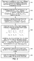
- FIG. 2 is a flow chart depicting an exemplary method for implementing features of the exemplary embodiments of the invention.
- FIG. 1 there is shown a pictorial diagram of an exemplary multi-user telecommunications system incorporating features of the exemplary embodiments of the invention. While discussed below with reference to the exemplary system shown in FIG. 1 , it should be appreciated that the exemplary embodiments of the invention may be utilized in conjunction with other systems and arrangements (e.g., of the various components).
- FIG. 1 there is shown a FWS 10 that is suitable for practicing exemplary embodiments of this invention.
- the FWS 10 employs direct sequence spread spectrum based CDMA techniques over an air link to provide local access to subscribers, and offers very high quality, highly reliable service.
- the FWS 10 is a S-CDMA communications system wherein FL transmissions from a base station, referred to also as a RBU 12 , with a plurality of transceiver units, referred to herein as users or SUs 14 , are symbol and chip aligned in time.
- the SUs 14 operate to receive the FL transmissions from the RBU 12 and to synchronize to one of the transmissions.
- Each SU 14 also transmits a signal on a RL to RBU 12 in order to synchronize the timing of its transmissions to the RBU 12 , and to generally perform bi-directional communications.
- the FWS 10 is suitable for use in implementing a telecommunications system that conveys multi-rate voice and/or data between the RBU 12 and the SUs 14 .
- the RBU 12 includes circuitry for generating a plurality of user signals (USER 1 to USER n , not shown in FIG. 1 ) and a synchronous side channel signal (SIDE chan , not shown in FIG. 1 ) that is substantially continuously transmitted. Each of these signals is assigned a respective PN spreading code and is modulated therewith before being applied to a transmitter 12 a for transmission via an antenna 12 b . When transmitted on the FL, the transmissions are modulated in phase quadrature and the SUs 14 are assumed to include suitable phase demodulators for deriving in-phase (I) and quadrature (Q) components therefrom.
- the RBU 12 is capable of transmitting a plurality of frequency channels. As a non-limiting example, each frequency channel may include up to 128 code channels and have a center frequency in the range of 2 GHz to 4 GHz.
- the RBU 12 also includes a receiver 12 c having an output coupled to an input of a side channel receiver 12 d .
- the side channel receiver 12 d receives as inputs the spread signal from the receiver 12 c , a scale factor signal, and a side channel despread PN code. These latter two signals are sourced from a RBU processor or controller 12 e .
- the scale factor signal can be fixed, or can be made adaptive as a function of the number of SUs 14 that are transmitting on the reverse channel, as non-limiting examples.
- the side channel receiver 12 d outputs a detect/not detect signal to the RBU controller 12 e indicating a detection (or non-detection) of a transmission from one of the SUs 14 , and also outputs a power estimate value.
- a read/write memory (MEM) 12 f is bi-directionally coupled to the RBU controller 12 e for storing system parameters and other information, such as SU timing phase information and power estimate values.
- a Network Interface Unit (NIU) 13 connects the RBU 12 to the public network, such as a public switched telephone network (PSTN) 13 a as a non-limiting example, through analog or digital trunks that are suitable for use with the local public network.
- the RBU 12 connects to the NIU 13 using E1 trunks and to its master antenna 12 b using a coaxial cable.
- the SU 14 communicates with the RBU 12 via the radio interface, as described above.
- the SU-RBU air link provides a separate 2.72 MHz (3.5 MHz including guard bands) channel in each direction separated by 91 MHz, 100 MHz, or 119 MHz of bandwidth.
- the nominal spectrum of operation is 2.1-2.3 GHz, 2.5-2.7 GHz, 3.4-3.6 GHz, or 3.5-3.7 GHz.
- the system is adaptable such that the frequency can be varied as required.
- An OVSF code set can be described by a matrix M having dimension SF max ⁇ SF max , where SF max is the maximum desired spreading factor (e.g., measured in chips/symbol) and a spreading code is a row of the matrix M.
- SF max is the maximum desired spreading factor (e.g., measured in chips/symbol)
- a spreading code is a row of the matrix M.
- Changing the number of chips per symbol varies the information symbol rate of the CDMA channel. For example, a chipping rate of 3.84 Mcps could support an information symbol rate of 30 ksps with a spreading factor of 128 chips/symbol and an information symbol rate of 60 ksps with a spreading factor of 64 chips/symbol.
- varying the spreading factor does not change the RF bandwidth of the transmitted DS-CDMA waveform, only the capacity measured in information bits or symbols per second.
- OVSF codes When properly assigned, OVSF codes have the property that all users, regardless of the data modulation and spreading factor (and CDMA channel rate), are preferably orthogonal or nearly orthogonal such that the cross-correlation between codes is acceptable.
- a non-recursive method for constructing OVSF PN code sets (e.g., for use in a CDMA communication system) is provided.
- SF max a maximum spreading factor
- SF min a minimum spreading factor
- B SF max /SF min , where SF max is the maximum desired spreading factor (e.g., measured in chips per modulated symbol) and SF min is the minimum desired spreading factor.
- C ′ [ M 1 , 1 ⁇ G 1 M 1 , 2 ⁇ G 2 ... M 1 , B ⁇ G B M 2 , 1 ⁇ G 1 M 2 , 2 ⁇ G 2 ... M 2 , B ⁇ G B ⁇ ⁇ ⁇ ⁇ M B , 1 ⁇ G 1 M B , 2 ⁇ G 2 ... M B , B ⁇ G B ]
- M i,j is a scalar from the i-th row and j-th column of the matrix M
- G k is a SF min ⁇ SF min base code matrix
- M i,j ⁇ G k denotes the multiplication of the elements of G k by the scalar M i,j .
- the function ⁇ ( ) represents a constrained, column-wise matrix permutation. From Giallorenzi et al., the constraint on the matrix permutation is designed to preserve the OVSF properties of the permuted matrix.
- the intermediate matrix, C′ is extended to be a more general family of OVSF code matrices constructed using a modulation matrix and a set of base code matrices.
- G1 [1 1; 1 ⁇ 1]
- G2 [ ⁇ 1 ⁇ 1; 1 ⁇ 1]
- G4 [ ⁇ 1 ⁇ 1; ⁇ 1 1]
- exemplary embodiments of this invention provide a non-recursive technique for constructing a series of mutually orthogonal sets of PN codes that support multi-rate signaling, where each of the sets of PN codes is selected for a predetermined time duration, such as an integer multiple of a user symbol time, for example.
- the sets of PN codes have the desirable properties that the constituent codes are at all of the desired symbol rates, and furthermore the constituent codes exhibit desirable spectral properties.
- Another aspect of the exemplary embodiments of this invention provides an improved technique for providing PN code structures for use in a communications system (e.g., a CDMA system) having a plurality of users simultaneously operating at different data rates or single data rates.
- a communications system e.g., a CDMA system
- a further aspect of exemplary embodiments of this invention provides a non-recursive technique for constructing a series of PN code sets that can be used to advantage in multi-rate synchronous and quasi-synchronous systems (e.g., CDMA systems), wherein the technique employs a permuted orthogonal matrix to modulate permuted orthogonal matrices to create multiple PN code sets that support multi-rate operation, where the multiple PN code sets may be selected for a predetermined time duration such as a user symbol time, for example.
- C ′ [ M 1 , 1 ⁇ G 1 M 1 , 2 ⁇ G 2 ... M 1 , B ⁇ G B M 2 , 1 ⁇ G 1 M 2 , 2 ⁇ G 2 ... M 2 , B ⁇ G B ⁇ ⁇ ⁇ ⁇ M B , 1 ⁇ G 1 M B , 2 ⁇ G 2 ... M B , B ⁇ G B ] , where M i,j is a scalar from the i-th row and j-th column of the modulation matrix M, G l . . .
- G B is the k-th base matrix G k and M i,j ⁇ G k denotes the multiplication of the elements of G k by the scalar M i,j ( 204 ); selecting a row of the OVSF code matrix C′ to use as a pseudo-noise (PN) code ( 205 ); and one of spreading or despreading a signal using the selected PN code ( 206 ).
- PN pseudo-noise
- the B unique base matrices G k comprise Hadamard matrices.
- the method is implemented within a multi-rate code division multiple access (CDMA) wireless communication system.
- the multi-rate CDMA wireless communication system comprises at least one fixed subscriber unit or at least one mobile subscriber unit.
- C ′ [ M 1 , 1 ⁇ G 1 M 1 , 2 ⁇ G 2 ... M 1 , B ⁇ G B M 2 , 1 ⁇ G 1 M 2 , 2 ⁇ G 2 ... M 2 , B ⁇ G B ⁇ ⁇ ⁇ ⁇ M B , 1 ⁇ G 1 M B , 2 ⁇ G 2 ... M B , B ⁇ G B ] , where M i,j is a scalar from the i-th row and j-th column of the modulation matrix M, G l . . .
- G B is the k-th base matrix G k and M i,j ⁇ G k denotes the multiplication of the elements of G k by the scalar M i,j ; and to select a row of the OVSF code matrix C′ to use as a pseudo-noise (PN) code; and a transceiver configured to transmit or receive a signal using the selected PN code.
- PN pseudo-noise
- the at least one processor is further configured to perform at least one constrained column-wise permutation on the OVSF code matrix C′ prior to selection of the row, where the constraint on the at least one constrained column-wise permutation is designed to preserve OVSF properties of the permuted code matrix C.
- the B unique base matrices G k comprise Hadamard matrices.
- the apparatus comprises a unit within a multi-rate code division multiple access (CDMA) wireless communication system.
- CDMA code division multiple access
- C ′ [ M 1 , 1 ⁇ G 1 M 1 , 2 ⁇ G 2 ... M 1 , B ⁇ G B M 2 , 1 ⁇ G 1 M 2 , 2 ⁇ G 2 ... M 2 , B ⁇ G B ⁇ ⁇ ⁇ ⁇ M B , 1 ⁇ G 1 M B , 2 ⁇ G 2 ... M B , B ⁇ G B ] , where M i,j is a scalar from the i-th row and j-th column of the modulation matrix M, G l . . .
- G B is the k-th base matrix G k and M i,j ⁇ G k denotes the multiplication of the elements of G k by the scalar M i,j ; means for selecting a row of the OVSF code matrix C′ to use as a pseudo-noise (PN) code; and one of means for spreading or means for despreading a signal using the selected PN code.
- PN pseudo-noise
- connection or coupling should be interpreted to indicate any such connection or coupling, direct or indirect, between the identified elements.
- one or more intermediate elements may be present between the “coupled” elements.
- the connection or coupling between the identified elements may be, as non-limiting examples, physical, electrical, magnetic, logical or any suitable combination thereof in accordance with the described exemplary embodiments.
- the connection or coupling may comprise one or more printed electrical connections, wires, cables, mediums or any suitable combination thereof.
- various exemplary embodiments of the invention can be implemented in different mediums, such as software, hardware, logic, special purpose circuits or any combination thereof.
- some aspects may be implemented in software which may be run on a computing device, while other aspects may be implemented in hardware.
Landscapes
- Engineering & Computer Science (AREA)
- Computer Networks & Wireless Communication (AREA)
- Signal Processing (AREA)
- Mobile Radio Communication Systems (AREA)
Abstract
where Mi,j is a scalar from the i-th row and j-th column of the modulation matrix M, Gl . . . GB is the k-th base matrix Gk and Mi,j·Gk denotes the multiplication of the elements of Gk by the scalar Mi,j; selecting a row of the OVSF code matrix C′ to use as a pseudo-noise (PN) code; and one of spreading or despreading a signal using the selected PN code.
Description
where Mi,j is a scalar from the i-th row and j-th column of the modulation matrix M, Gl . . . GB is the k-th base matrix Gk and Mi,j·Gk denotes the multiplication of the elements of Gk by the scalar Mi,j; selecting a row of the OVSF code matrix C′ to use as a pseudo-noise (PN) code; and one of spreading or despreading a signal using the selected PN code.
where Mi,j is a scalar from the i-th row and j-th column of the modulation matrix M, Gl . . . GB is the k-th base matrix Gk and Mi,j·Gk denotes the multiplication of the elements of Gk by the scalar Mi,j; and to select a row of the OVSF code matrix C′ to use as a pseudo-noise (PN) code; and a transceiver configured to transmit or receive a signal using the selected PN code.
C=Π(C′)
4×4 Modulation Matrix:
8×8 Unpermuted OVSF Code Matrix:
where Mi,j is a scalar from the i-th row and j-th column of the modulation matrix M, Gl . . . GB is the k-th base matrix Gk and Mi,j·Gk denotes the multiplication of the elements of Gk by the scalar Mi,j (204); selecting a row of the OVSF code matrix C′ to use as a pseudo-noise (PN) code (205); and one of spreading or despreading a signal using the selected PN code (206).
where Mi,j is a scalar from the i-th row and j-th column of the modulation matrix M, Gl . . . GB is the k-th base matrix Gk and Mi,j·Gk denotes the multiplication of the elements of Gk by the scalar Mi,j; and to select a row of the OVSF code matrix C′ to use as a pseudo-noise (PN) code; and a transceiver configured to transmit or receive a signal using the selected PN code.
where Mi,j is a scalar from the i-th row and j-th column of the modulation matrix M, Gl . . . GB is the k-th base matrix Gk and Mi,j·Gk denotes the multiplication of the elements of Gk by the scalar Mi,j; means for selecting a row of the OVSF code matrix C′ to use as a pseudo-noise (PN) code; and one of means for spreading or means for despreading a signal using the selected PN code. An apparatus as in the previous, further comprising one or more additional aspects of the exemplary embodiments of the invention as further described herein.
Claims (14)
Priority Applications (1)
| Application Number | Priority Date | Filing Date | Title |
|---|---|---|---|
| US12/080,131 US7609749B1 (en) | 2003-07-17 | 2008-03-31 | Method and apparatus for generating non-recursive variable rate orthogonal spreading codes |
Applications Claiming Priority (2)
| Application Number | Priority Date | Filing Date | Title |
|---|---|---|---|
| US62289503A | 2003-07-17 | 2003-07-17 | |
| US12/080,131 US7609749B1 (en) | 2003-07-17 | 2008-03-31 | Method and apparatus for generating non-recursive variable rate orthogonal spreading codes |
Related Parent Applications (1)
| Application Number | Title | Priority Date | Filing Date |
|---|---|---|---|
| US62289503A Continuation-In-Part | 2003-07-17 | 2003-07-17 |
Publications (1)
| Publication Number | Publication Date |
|---|---|
| US7609749B1 true US7609749B1 (en) | 2009-10-27 |
Family
ID=41211126
Family Applications (1)
| Application Number | Title | Priority Date | Filing Date |
|---|---|---|---|
| US12/080,131 Expired - Lifetime US7609749B1 (en) | 2003-07-17 | 2008-03-31 | Method and apparatus for generating non-recursive variable rate orthogonal spreading codes |
Country Status (1)
| Country | Link |
|---|---|
| US (1) | US7609749B1 (en) |
Cited By (2)
| Publication number | Priority date | Publication date | Assignee | Title |
|---|---|---|---|---|
| US20170111135A1 (en) * | 2015-07-13 | 2017-04-20 | Nathan Hays | Signal coding for improved spectral quality |
| WO2019125253A1 (en) * | 2017-12-21 | 2019-06-27 | Telefonaktiebolaget Lm Ericsson (Publ) | Construction and application of an orthogonal code |
Citations (6)
| Publication number | Priority date | Publication date | Assignee | Title |
|---|---|---|---|---|
| US5571761A (en) | 1986-08-22 | 1996-11-05 | Canon Kabushiki Kaisha | Ceramic substrate circuit substrate |
| US6091760A (en) | 1998-06-29 | 2000-07-18 | L-3 Communications Corporation | Non-recursively generated orthogonal PN codes for variable rate CDMA |
| US6163524A (en) | 1998-10-19 | 2000-12-19 | Telefonaktiebolaget Lm Ericsson (Publ) | Code allocation in CDMA |
| US20010043644A1 (en) | 2000-05-16 | 2001-11-22 | Koninklijke Philips Electronics N.V. | Method of despreading a spread spectrum signal |
| US20020006156A1 (en) * | 2000-03-30 | 2002-01-17 | Mitsubishi Electric Telecom Europe (S.A.) | Spread spectrum modulation method with discontinuous spreading code, corresponding demodulation method, mobile station and base stations |
| US6965582B1 (en) | 1999-05-21 | 2005-11-15 | Koninklijke Philips Electronics N.V. | Cellular radio communication system |
-
2008
- 2008-03-31 US US12/080,131 patent/US7609749B1/en not_active Expired - Lifetime
Patent Citations (6)
| Publication number | Priority date | Publication date | Assignee | Title |
|---|---|---|---|---|
| US5571761A (en) | 1986-08-22 | 1996-11-05 | Canon Kabushiki Kaisha | Ceramic substrate circuit substrate |
| US6091760A (en) | 1998-06-29 | 2000-07-18 | L-3 Communications Corporation | Non-recursively generated orthogonal PN codes for variable rate CDMA |
| US6163524A (en) | 1998-10-19 | 2000-12-19 | Telefonaktiebolaget Lm Ericsson (Publ) | Code allocation in CDMA |
| US6965582B1 (en) | 1999-05-21 | 2005-11-15 | Koninklijke Philips Electronics N.V. | Cellular radio communication system |
| US20020006156A1 (en) * | 2000-03-30 | 2002-01-17 | Mitsubishi Electric Telecom Europe (S.A.) | Spread spectrum modulation method with discontinuous spreading code, corresponding demodulation method, mobile station and base stations |
| US20010043644A1 (en) | 2000-05-16 | 2001-11-22 | Koninklijke Philips Electronics N.V. | Method of despreading a spread spectrum signal |
Non-Patent Citations (2)
| Title |
|---|
| Davidson, I.A., "The Use of Walsh Functions For Multiplexing Signals", Research and Development Laboratories Northern Electric Company Ltd., Ottawa, Canada, pp. 23-25, 1970 Proceedings. |
| Hubner, H., "On The Transmission of Walsh Modulated Multiplex Signals", Research Institute of the Telecommunication Engineering Centre of the Deutsche Bundespost, Dermstadt, Western Germany, pp. 41-45, 1970 Proceeding. |
Cited By (4)
| Publication number | Priority date | Publication date | Assignee | Title |
|---|---|---|---|---|
| US20170111135A1 (en) * | 2015-07-13 | 2017-04-20 | Nathan Hays | Signal coding for improved spectral quality |
| US9991984B2 (en) * | 2015-07-13 | 2018-06-05 | Terrace Communications Corporation | Signal coding for improved spectral quality |
| WO2019125253A1 (en) * | 2017-12-21 | 2019-06-27 | Telefonaktiebolaget Lm Ericsson (Publ) | Construction and application of an orthogonal code |
| US11515959B2 (en) | 2017-12-21 | 2022-11-29 | Telefonaktiebolaget Lm Ericsson (Publ) | Construction and application of an orthogonal code |
Similar Documents
| Publication | Publication Date | Title |
|---|---|---|
| US6982946B2 (en) | Partly orthogonal multiple code trees | |
| US6091760A (en) | Non-recursively generated orthogonal PN codes for variable rate CDMA | |
| US6563808B1 (en) | Apparatus for incorporating multiple data rates in an orthogonal direct sequence code division multiple access (ODS-CDMA) communications system | |
| KR100691603B1 (en) | Communication methods and apparatus based on orthogonal hadamard-based sequences having selected correlation properties | |
| US7468943B2 (en) | Transmission/Reception apparatus and method in a mobile communication system | |
| KR100369801B1 (en) | Apparatus and method for generating band-spread signal using pseudo-orthogonal code of cdma mobile communication system | |
| KR19990024992A (en) | Quasi-orthogonal code generation in a code division multiple access communication system, spreading apparatus and method using the same | |
| US6724741B1 (en) | PN code selection for synchronous CDMA | |
| US8848675B2 (en) | Time-division multiplexed pilot signal for integrated mobile broadcasts | |
| US6574269B1 (en) | Asymmetric orthogonal codes for wireless system receivers with multiplication-free correlators | |
| US6963601B1 (en) | Apparatus and method for spreading channel data in CDMA communication system using orthogonal transmit diversity | |
| US7536168B2 (en) | Method, emitter and receiver for transmitting data in a multi-access CDMA system by fully complementary code matrixes for two-dimensional data spreading in a frequency and time direction | |
| US7085307B2 (en) | Methods and apparatus for transmitting data over a CDMA network | |
| KR100465315B1 (en) | System for spreading/inverse spreading of Multicarrier-Code Division Multiple Access and method thereof | |
| US7609749B1 (en) | Method and apparatus for generating non-recursive variable rate orthogonal spreading codes | |
| Lu et al. | Extended orthogonal polyphase codes for multicarrier CDMA system | |
| US7586835B2 (en) | Apparatus for generating 2D spreading code and method for the same | |
| CN101288253B (en) | Method and system for spreading and scrambling downlike physical channels | |
| Wysocki et al. | Orthogonal binary sequences with wide range of correlation properties | |
| JPH0865264A (en) | Method and equipment for communication for cdma system using spread spectrum modulation | |
| JPH0846591A (en) | Spread spectrum communication system | |
| Wu | RS-CTDMA: a novel concept of multiple access design | |
| KR20070074381A (en) | Cdma communication apparatus and system using quasi-orthogonal spreading sequence with guard interval sequence | |
| Stanczak et al. | QS-CDMA: a potential air interface candidate for 4G wireless communications | |
| JPH0795177A (en) | Code division multiple address communication system |
Legal Events
| Date | Code | Title | Description |
|---|---|---|---|
| AS | Assignment |
Owner name: L-3 COMMUNICATIONS CORPORATION, NEW YORK Free format text: ASSIGNMENT OF ASSIGNORS INTEREST;ASSIGNORS:HALL, ERIC K.;GIALLORENZI, THOMAS R.;ERTEL, RICHARD B.;REEL/FRAME:020959/0792;SIGNING DATES FROM 20080424 TO 20080510 |
|
| STCF | Information on status: patent grant |
Free format text: PATENTED CASE |
|
| FPAY | Fee payment |
Year of fee payment: 4 |
|
| FPAY | Fee payment |
Year of fee payment: 8 |
|
| MAFP | Maintenance fee payment |
Free format text: PAYMENT OF MAINTENANCE FEE, 12TH YEAR, LARGE ENTITY (ORIGINAL EVENT CODE: M1553); ENTITY STATUS OF PATENT OWNER: LARGE ENTITY Year of fee payment: 12 |
|
| AS | Assignment |
Owner name: L3 TECHNOLOGIES, INC., FLORIDA Free format text: CHANGE OF NAME;ASSIGNOR:L-3 COMMUNICATIONS CORPORATION;REEL/FRAME:063295/0788 Effective date: 20161231 |