US7602268B2 - Operation input device and electronic equipment employing the same - Google Patents
Operation input device and electronic equipment employing the same Download PDFInfo
- Publication number
- US7602268B2 US7602268B2 US11/396,828 US39682806A US7602268B2 US 7602268 B2 US7602268 B2 US 7602268B2 US 39682806 A US39682806 A US 39682806A US 7602268 B2 US7602268 B2 US 7602268B2
- Authority
- US
- United States
- Prior art keywords
- input device
- base
- dial
- operation plate
- disc type
- Prior art date
- Legal status (The legal status is an assumption and is not a legal conclusion. Google has not performed a legal analysis and makes no representation as to the accuracy of the status listed.)
- Expired - Fee Related, expires
Links
Images


Classifications
-
- B—PERFORMING OPERATIONS; TRANSPORTING
- B66—HOISTING; LIFTING; HAULING
- B66C—CRANES; LOAD-ENGAGING ELEMENTS OR DEVICES FOR CRANES, CAPSTANS, WINCHES, OR TACKLES
- B66C13/00—Other constructional features or details
- B66C13/18—Control systems or devices
- B66C13/40—Applications of devices for transmitting control pulses; Applications of remote control devices
- B66C13/44—Electrical transmitters
-
- G—PHYSICS
- G06—COMPUTING; CALCULATING OR COUNTING
- G06F—ELECTRIC DIGITAL DATA PROCESSING
- G06F3/00—Input arrangements for transferring data to be processed into a form capable of being handled by the computer; Output arrangements for transferring data from processing unit to output unit, e.g. interface arrangements
- G06F3/01—Input arrangements or combined input and output arrangements for interaction between user and computer
- G06F3/03—Arrangements for converting the position or the displacement of a member into a coded form
- G06F3/033—Pointing devices displaced or positioned by the user, e.g. mice, trackballs, pens or joysticks; Accessories therefor
- G06F3/0362—Pointing devices displaced or positioned by the user, e.g. mice, trackballs, pens or joysticks; Accessories therefor with detection of 1D translations or rotations of an operating part of the device, e.g. scroll wheels, sliders, knobs, rollers or belts
-
- B—PERFORMING OPERATIONS; TRANSPORTING
- B66—HOISTING; LIFTING; HAULING
- B66C—CRANES; LOAD-ENGAGING ELEMENTS OR DEVICES FOR CRANES, CAPSTANS, WINCHES, OR TACKLES
- B66C13/00—Other constructional features or details
- B66C13/04—Auxiliary devices for controlling movements of suspended loads, or preventing cable slack
- B66C13/06—Auxiliary devices for controlling movements of suspended loads, or preventing cable slack for minimising or preventing longitudinal or transverse swinging of loads
- B66C13/063—Auxiliary devices for controlling movements of suspended loads, or preventing cable slack for minimising or preventing longitudinal or transverse swinging of loads electrical
-
- G—PHYSICS
- G05—CONTROLLING; REGULATING
- G05G—CONTROL DEVICES OR SYSTEMS INSOFAR AS CHARACTERISED BY MECHANICAL FEATURES ONLY
- G05G9/00—Manually-actuated control mechanisms provided with one single controlling member co-operating with two or more controlled members, e.g. selectively, simultaneously
- G05G9/02—Manually-actuated control mechanisms provided with one single controlling member co-operating with two or more controlled members, e.g. selectively, simultaneously the controlling member being movable in different independent ways, movement in each individual way actuating one controlled member only
- G05G9/04—Manually-actuated control mechanisms provided with one single controlling member co-operating with two or more controlled members, e.g. selectively, simultaneously the controlling member being movable in different independent ways, movement in each individual way actuating one controlled member only in which movement in two or more ways can occur simultaneously
- G05G9/047—Manually-actuated control mechanisms provided with one single controlling member co-operating with two or more controlled members, e.g. selectively, simultaneously the controlling member being movable in different independent ways, movement in each individual way actuating one controlled member only in which movement in two or more ways can occur simultaneously the controlling member being movable by hand about orthogonal axes, e.g. joysticks
-
- G—PHYSICS
- G06—COMPUTING; CALCULATING OR COUNTING
- G06F—ELECTRIC DIGITAL DATA PROCESSING
- G06F3/00—Input arrangements for transferring data to be processed into a form capable of being handled by the computer; Output arrangements for transferring data from processing unit to output unit, e.g. interface arrangements
- G06F3/01—Input arrangements or combined input and output arrangements for interaction between user and computer
- G06F3/03—Arrangements for converting the position or the displacement of a member into a coded form
- G06F3/033—Pointing devices displaced or positioned by the user, e.g. mice, trackballs, pens or joysticks; Accessories therefor
- G06F3/0338—Pointing devices displaced or positioned by the user, e.g. mice, trackballs, pens or joysticks; Accessories therefor with detection of limited linear or angular displacement of an operating part of the device from a neutral position, e.g. isotonic or isometric joysticks
-
- B—PERFORMING OPERATIONS; TRANSPORTING
- B66—HOISTING; LIFTING; HAULING
- B66C—CRANES; LOAD-ENGAGING ELEMENTS OR DEVICES FOR CRANES, CAPSTANS, WINCHES, OR TACKLES
- B66C2700/00—Cranes
- B66C2700/08—Electrical assemblies or electrical control devices for cranes, winches, capstans or electrical hoists
Definitions
- the present invention relates to an operation input device which is applicable to a portable telephone or a portable music player.
- an operation input device for use in a portable telephone or the like has been, for example, one including a base, a printed circuit board which has a plurality of pushbutton switches and magnetic field detecting elements mounted on its upside and which is stacked on and united with the base, an operation plate which is placed on the printed circuit board, and a disc type operation dial in which an annular magnet with N-poles and S-poles arranged alternately is assembled on the underside of the operation dial and which is turnably assembled on the operation plate.
- the operation dial With the operation input device, the operation dial is turned, whereby the changes of the magnetic fluxes of the annular magnet are sensed by the magnetic field detecting elements so as to detect a turning direction, while the operation dial is depressed, whereby the pushbutton switch is operated (refer to JP-A-2003-280799).
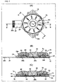
- the operation input device is schematically shown in FIG. 19 .
- the peripheral edge of a rotary member (operation dial) 154 is retained through a retaining ring 164 which is mounted on a base 120 .
- the rotary member (operation dial) 154 is subjected to a turning operation and a depressing operation, thereby to drive any of pushbutton switches not shown.
- the upper peripheral edge of the rotary member 154 abuts against the retaining ring 164 in depressing the peripheral edge of this rotary member 154 , an operation feeling worsens, and hence, some gap G 1 is provided. Due to the provision of the gap G 1 , however, the rotary member 154 becomes rickety in a vertical direction.
- the present invention has for its object to provide an operation input device of good operation feeling, which removes the vertical ricketiness of an operation dial and ensures a smooth turning operation.
- an operation input device consists in comprising a base, a printed circuit board which has a plurality of pushbutton switches and magnetic field detecting elements mounted on its upside and which is stacked on and united with the base, an operation plate which is supported on the base so as to be vertically movable on the printed circuit board, and a disc type operation dial in which an annular magnet with N-poles and S-poles arranged alternately is assembled on an underside of the operation dial and which is turnably assembled on an upside of the operation plate; wherein the disc type operation dial is turned, thereby to sense changes of magnetic fluxes of the annular magnet by the magnetic field detecting elements and to detect a turning direction, while the disc type operation dial is depressed, thereby to operate any of the pushbutton switches through the operation plate.
- a depressing operation function is allotted to the operation plate which is supported on the base so as to be vertically movable, while a turning operation function is allotted to the operation dial which is turnably assembled on the upside of the operation plate. Therefore, the vertical ricketiness can be eliminated, and a smooth turning operation is permitted, so that the operation input device of good operation feeling is obtained.
- the outer peripheral edge parts of a slide sheet which is arranged between the operation plate and the disc type operation dial are supported by the base, thereby to bestow urging forces on the operation plate.
- the slide sheet urges the operation plate downwards, so that the vertical ricketiness of the operation plate can be prevented more reliably, and the operation feeling is enhanced.
- an operation input device may well comprise a base, a printed circuit board which has a plurality of pushbutton switches and magnetic field detecting elements mounted on its upside and which is stacked on and united with the base, an operation plate which is arranged on the printed circuit board, a disc type operation dial in which an annular magnet with N-poles and S-poles arranged alternately is assembled on an underside of the operation dial and which is turnably assembled on an upside of the operation plate, and a flexible slide sheet which is arranged between the operation plate and the disc type operation dial and whose outer peripheral edge parts are supported by the base; wherein the disc type operation dial is turned, thereby to sense changes of magnetic fluxes of the annular magnet by the magnetic field detecting elements and to detect a turning direction, while the disc type operation dial is depressed, thereby to operate any of the pushbutton switches through the operation plate.
- the operation plate is supported through the flexible slide sheet supported on the base.
- a depressing operation function is allotted to the slide sheet and the operation plate, while a turning operation function is allotted to the operation dial which is turnably assembled on the upside of the operation plate. Therefore, the vertical ricketiness can be eliminated, and a smooth turning operation is permitted, so that the operation input device of good operation feeling is obtained.
- the operation plate may well have its underside pushed up by elastic arms cut and raised from the base, thereby to be urged upwards.
- the operation plate is pushed upwards, so that superfluous loads do not act on the pushbutton switches, and any maloperation can be prevented. Moreover, since the operation plate need not be pushed up by elastic arms being separate members, the number of components and the number of assembling man-hour are small, and the operation input device of high productivity is obtained.
- elastic pads may well be arranged between the pushbutton switches and the operation plate.
- the compressed elastic pads urge the operation plate upwards, and the vertical ricketiness can be prevented. Moreover, since the elastic pads absorb an assemblage error, a high assemblage precision is not required, and the fabrication of the operation input device is facilitated.
- An electronic equipment consists in that the operation input device mentioned above is mounted with the disc type operation dial exposed so as to be operable from outside.
- FIG. 1A is a front view of a portable telephone in which the first embodiment of an operation input device according to the present invention is incorporated;
- FIG. 1B is an enlarged front view of the operation input device
- FIGS. 2A and 2B are perspective views in which the operation input device shown in FIGS. 1A and 1B is seen from above and from below, respectively;
- FIG. 3 is an exploded perspective view in which parts of the operation input device shown in FIG. 2A are disassembled and seen from above;
- FIG. 4 is an exploded perspective view in which the operation input device shown in FIG. 2A is seen from above;
- FIG. 5 is an exploded perspective view in which parts of the operation input device shown in FIG. 2B are disassembled and seen from below;
- FIG. 6 is an exploded perspective view in which the operation input device shown in FIG. 2B is seen from below;
- FIGS. 7A , 7 B and 7 C are a front view of the operation input device shown in FIG. 1 , and sectional views taken along a line B-B and a line C-C indicated in FIG. 7A , respectively;
- FIGS. 8A , 8 B and 8 C are a front view of the operation input device shown in FIG. 1 , and sectional views taken along a line B-B and a line C-C indicated in FIG. 8A , respectively;
- FIGS. 9A and 9B are perspective views in which the second embodiment of the operation input device according to the invention is seen from above and from below, respectively;
- FIGS. 10A and 10B are sectional views which correspond to the perspective views shown in FIGS. 9A and 9B , respectively;
- FIG. 11 is an exploded perspective view in which the operation input device shown in FIG. 9A is seen from above;
- FIG. 12 is an exploded perspective view in which the operation input device shown in FIG. 9B is seen from below;
- FIGS. 13A , 13 B and 13 C are a front view of the operation input device shown in FIGS. 9A and 9B , and sectional views taken along a line B-B and a line C-C indicated in FIG. 13A , respectively;
- FIGS. 14A and 14B are perspective views in which the third embodiment of the operation input device according to the invention is seen from above and from below, respectively;
- FIGS. 15A and 15B are sectional views which correspond to the perspective views shown in FIGS. 14A and 14B , respectively;
- FIG. 16 is an exploded perspective view in which the operation input device shown in FIG. 14A is seen from above;
- FIG. 17 is an exploded perspective view in which the operation input device shown in FIG. 14B is seen from below;
- FIG. 18 is a schematic sectional view showing the operating principle of the operation input device according to the invention.
- FIG. 19 is schematic sectional views showing the operating principle of an operation input device in a prior-art example.
- the operation input device in each embodiment is applied to a portable telephone.
- a scroll bar (not shown) within a monitor 2 disposed in the portable telephone 1 is scrolled by the operation input device 3 , whereby a selection instruction can be given through a pushbutton 40 , etc. to be stated below.
- numeral 4 designates ten-keys, numeral 5 a microphone, and numeral 6 a loudspeaker.
- the operation input device 3 includes a metal base 10 on and with which a flexible printed circuit board 20 is stuck and united, a resin-made film cover 30 which has a center pushbutton switch 29 a and four pushbutton switches 29 b - 29 e stuck on its underside beforehand, the pushbutton 40 which operates the center pushbutton switch 29 a , an operation plate 50 which is supported on the metal base 10 , a slide sheet 60 which is placed on the upside of the operation plate 50 , and an operation dial 70 which has an annular magnet 65 fitted and fixed and has a fixation ring 45 clinched and fixed on its underside and which is turnably mounted on the operation plate 50 .
- the metal base 10 is substantially rectangular in plan, and it has a pair of positioning pillars 11 , 11 cut and erected at its central parts and is provided with jig holes 12 , 12 outside the respective positioning pillars. Besides, the metal base 10 has elastic engagement receivers 13 cut and erected centrally of the edges of its respective latera.
- the printed circuit board 20 made of a flexible resin film is formed of a circuit board body 20 a of substantially rectangular shape, whose rear surface is coated with a bonding material and is clad with peeling paper, and a lead portion 20 b which extends from the circuit board body 20 a .
- the circuit board body 20 a is centrally provided with a concentric conductive portion 21 a , and it has concentric conductive portions 21 b , 21 c , 21 d , 21 e arranged crosswise about the conductive portion 21 a thereon.
- the printed circuit board 20 is provided with positioning holes 22 and jig holes 23 at positions which correspond respectively to the positioning pillars 11 and jig holes 12 of the metal base 10 .
- LEDs 24 for notifying an operating state are mounted on the respective corner parts of the circuit board body 20 a , and a pair of Hall elements 25 a , 25 b are mounted on this circuit board body 20 a so as to oppose to each other with the conductive portion 21 a interposed therebetween.
- the conductive portions 21 a - 21 e are not restricted to only the concentric ones.
- Each of these conductive portions may well be, for example, such that one conductive portion which is substantially C-shaped in plan has the other conductive portion arranged centrally so as to be led out.
- the resin-made film cover 30 has a planar shape in which this film cover can be mounted on the circuit board body 20 a .
- This resin-made film cover 30 is provided with sticking portions 31 a - 31 e at those positions of its rear surface coated with a bonding material which correspond to the respective conductive portions 21 a - 21 e .
- Flat dome-shaped inversion springs which form the pushbutton switches 29 a - 29 e , are respectively stuck to the sticking portions 31 a - 31 e .
- the resin-made film cover 30 is provided with positioning holes 32 and jig holes 33 at positions which correspond respectively to the positioning pillars 11 and jig holes 12 of the metal base 10 .
- the pushbutton 40 has an outer peripheral shape in which this pushbutton can be inserted into the operation hole 71 of the operation dial 70 to be stated later.
- a coming-off preventive annular rib 41 is unitarily molded at the edge part of the lower end of the outer periphery of the pushbutton 40 .
- the pushbutton 40 is protrusively provided with a depressing lug 42 ( FIG. 6 ) centrally of its bottom surface, and it is formed with guiding slits 43 which engage the respective positioning pillars 11 of the metal base 10 , in the outer peripheral surface of the annular rib 41 .
- the fixation ring 45 is clinched and fixed onto the underside of the operation dial 70 to be stated later, thereby to turnably assemble the operation dial 70 to the operation plate 50 .
- the operation plate 50 is a resin-molded article which is substantially rectangular in plan, and which can cover the metal base 10 .
- This operation plate 50 is centrally provided with a fitting hole 51 , and it is formed with an annular step 52 at the peripheral edge part of the underside of the fitting hole 51 ( FIG. 6 ).
- the operation plate 50 is protrusively provided with depressing lugs 53 b - 53 e at positions which correspond to the respective sticking portions 31 b - 31 e of the resin-made film cover 30 .
- the operation plate 50 is provided with rectangular holes 54 at positions which correspond to the respective Hall elements 25 a , 25 b , and it is provided with elastic pawls 55 centrally of the edge parts of the respective latera in a manner to protrude sideward.
- the rectangular holes 54 are provided in order to facilitate the passages of magnetic fluxes.
- the slide sheet 60 has a concentric circular shape in which this slide sheet can cover the upside of the operation plate 50 , and it is provided with elastic tongues 61 which engage the respective elastic engagement receivers 13 of the metal base 10 , at its outer peripheral edge parts.
- the annular magnet 65 has N-poles and S-poles arranged alternately, and it is fitted and fixed into the annular groove 75 of the operation dial 70 to be stated later.
- the annular magnet 65 is embedded in the annular groove 75 of the operation dial 70 , and it does not lie in direct touch with the slide sheet 60 .
- the operation dial 70 is centrally provided with the operation hole 71 into which the pushbutton 40 is fitted, and it is provided with antiskid raises 72 at the peripheral parts of its upside in a manner to extend radially and to lie at equal pitches.
- the operation dial 70 is concentrically provided with an annular protrusion 73 for clinching and fixing the fixation ring 45 , at the peripheral edge part of the underside of the operation hole 71 , and it is protrusively provided with clinching projections 74 on the lower surface of the annular projection 73 .
- the operation dial 70 is concentrically provided with the annular groove 75 for fitting and fixing the annular magnet 65 thereinto, outside the annular protrusion 73 .
- the disc type operation dial 70 need not always be circular, but it may well be in the shape of, for example, an equilateral octagon as long as it is turnable.
- the jig holes 12 of the metal base 10 are respectively set to one pair of positioning pins of a jig not shown, thereby to position this metal base 10 .
- the jig holes 23 and positioning holes 22 of the printed circuit board 20 on which the Hall elements 25 a , 25 b and the LEDs 24 are mounted at their predetermined positions are respectively set to the pair of pins of the jig and the positioning pillars 11 of the metal base 10 , thereby to stick and unite the printed circuit board 20 to and with the metal base 10 .
- the dome-shaped inversion springs to become the pushbutton switches 29 a - 29 e are respectively stuck and united to and with the sticking portions 31 a - 31 e of the resin-made film cover 30 .
- the jig holes 33 and positioning holes 32 of the resin-made film cover 30 are respectively set to the pair of positioning pins of the jig and the positioning pillars 11 of the metal base 10 , whereby the resin film 30 is stuck and united to and with the printed circuit board 20 , and the pushbutton switches 29 a - 29 e made up of the inversion springs stuck to the resin film 30 are formed.
- the annular magnet 65 is fitted into the annular groove 75 of the operation dial 70 and is bonded and fixed thereto.
- the slide sheet 60 is positioned onto the upside of the operation plate 50 , and the annular protrusion 73 of the operation dial 70 is fitted into the fitting hole 51 .
- the fixation fitting 45 is positioned to the annular protrusion 73 of the operation dial 70 , and the clinching projections 74 of the annular protrusion 73 are inserted into the clinching holes 46 of the fixation fitting 45 and are clinched.
- the operation plate 50 and the slide sheet 60 are held between the operation dial 70 and the fixation ring 45 , and the operation dial 70 is turnably supported on the operation plate 50 through the slide sheet 60 .
- the pushbutton 40 is positioned over the pushbutton switch 29 a of the printed circuit board 20 . Further, the pushbutton 40 is fitted into the fitting hole 71 of the operation dial 70 , and the elastic pawls 55 of the operation plate 50 and the elastic tongues 61 of the slide sheet 60 are engaged with the elastic engagement receivers 13 of the metal base 10 , whereby the assembling operations are completed.
- the elastic tongues 61 of the slide sheet 60 are engaged with the elastic engagement receivers 13 in a state where they are somewhat bent downward, so as to generate urging forces.
- the operation plate 50 is unturnably fixed to the base 10 , and the operation dial 70 is depressed, thereby to bear the depression operation function of depressing the pushbutton switches 29 a - 29 e .
- the operation dial 70 turnably assembled onto the upside of the operation plate 50 is turned, thereby to bear a turning operation function.
- the elastic pawls 55 of the operation plate 50 are held in engagement with the elastic engagement receivers 13 of the base 10 , so that the operation plate 50 can be prevented from becoming rickety in a horizontal direction.
- the operation plate 50 is urged upwards by the spring forces of the pushbutton switches, so that it undergoes no ricketiness in a vertical direction.
- the elastic tongues 61 of the slide sheet 60 are held in engagement with the elastic engagement receivers 13 , thereby to urge the operation plate 50 downwards, so that the vertical ricketiness of the operation plate 50 can be prevented more reliably.
- the slide sheet 60 urges the operation dial 70 also upwards. Therefore, the operation dial 70 can be restrained from excessively turning due to an inertial force, to bring forth the advantage that any erroneous operation is difficult to occur.
- the operation plate 50 and the operation dial 70 may well be supported in such a way that only the elastic tongues 61 of the slide sheet 60 arranged between the operation plate 50 and the operation dial 70 are engaged with the elastic engagement receivers 13 of the base 10 .
- the results of the detections are reflected as the movement of the scroll bar on the screen display of the monitor 2 through a control circuit not shown. Subsequently, in a case where the scroll bar has arrived at a desired position, the pushbutton 40 is depressed, whereby the center pushbutton switch 29 a is operated by the depressing lug 42 so as to output a selection command.
- the peripheral part of the operation dial 70 as corresponds to, for example, the depressing lug 53 e shown in FIG. 8B may well be depressed, thereby to invert and turn ON the inversion spring of the pushbutton switch 29 e lying directly under the depressing lug 53 e.
- the second embodiment of the invention corresponds to a case where an operation plate 50 is urged upwards by elastic arms 14 which are cut and raised from the peripheral edge parts of a metal base 10 , thereby to prevent the operation plate 50 from becoming rickety in a vertical direction.
- the same parts as in the first embodiment are assigned the same reference numerals and signs, and they shall be omitted from description.
- the operation plate 50 is pushed upwards, so that superfluous loads do not act on pushbutton switches 29 a - 29 e , and any maloperation can be prevented. Moreover, since elastic arms being separate members are not required, the number of components and the number of assembling man-hour are small, and an operation input device of high productivity is obtained.
- the third embodiment of the invention corresponds to a case where elastic pads 34 are respectively placed on pushbutton switches 21 a - 21 e through a resin-made film cover 30 .
- the same parts as in the first embodiment are assigned the same reference numerals and signs, and they shall be omitted from description.
- the resin-made film cover 30 is not shown in FIGS. 14A through 15C .
- the elastic pads 34 are placed so as to push an operation plate 50 upwards, whereby the operation plate 50 can be prevented from becoming rickety in a vertical direction. Especially, since the elastic pads 34 can absorb a cumulative error ascribable to the assemblage of a large number of components, a high assemblage precision is not required, and an operation input device easy of fabrication is obtained.
- FIG. 18 illustrates the principle stated above.
- Elastic members urging the operation plate 50 in the figure correspond to the slide sheet 60 , elastic arms 14 and elastic pads 34 in the respective embodiments stated above.
- the ricketiness may well be prevented in such a way that the elastic pads are arranged between the upside of the printed circuit board 20 and the underside of the operation plate 50 so as to urge this operation plate 50 upwards.
- the operation input device according to the invention is not restricted to the portable telephone, but that it may well be applied to another mobile equipment or any other electronic equipment.
Landscapes
- Engineering & Computer Science (AREA)
- General Engineering & Computer Science (AREA)
- Theoretical Computer Science (AREA)
- Physics & Mathematics (AREA)
- General Physics & Mathematics (AREA)
- Human Computer Interaction (AREA)
- Automation & Control Theory (AREA)
- Mechanical Engineering (AREA)
- Switches With Compound Operations (AREA)
- Position Input By Displaying (AREA)
- Switch Cases, Indication, And Locking (AREA)
Abstract
An operation input device includes a base, a printed circuit board which has a plurality of pushbutton switches and Hall elements mounted on its upside and which is stacked on and united with the base, an operation plate which is supported on the base so as to be vertically movable on the printed circuit board, and a disc type operation dial in which an annular magnet with N-poles and S-poles arranged alternately is assembled on the underside of this operation dial and which is turnably assembled on the upside of the operation plate. Here, the disc type operation dial is turned, thereby to sense the changes of the magnetic fluxes of the annular magnet by the Hall elements and to detect a turning direction, while the disc type operation dial is depressed, thereby to operate any of the pushbutton switches through the operation plate. The operation dial is prevented from becoming rickety in a horizontal direction, and it ensures a smooth turning operation, thereby to afford a good operation feeling.
Description
1. Field of the Invention
The present invention relates to an operation input device which is applicable to a portable telephone or a portable music player.
2. Description of the Related Art
Heretofore, an operation input device for use in a portable telephone or the like has been, for example, one including a base, a printed circuit board which has a plurality of pushbutton switches and magnetic field detecting elements mounted on its upside and which is stacked on and united with the base, an operation plate which is placed on the printed circuit board, and a disc type operation dial in which an annular magnet with N-poles and S-poles arranged alternately is assembled on the underside of the operation dial and which is turnably assembled on the operation plate. With the operation input device, the operation dial is turned, whereby the changes of the magnetic fluxes of the annular magnet are sensed by the magnetic field detecting elements so as to detect a turning direction, while the operation dial is depressed, whereby the pushbutton switch is operated (refer to JP-A-2003-280799).
The operation input device is schematically shown in FIG. 19 . As seen from the figure, the peripheral edge of a rotary member (operation dial) 154 is retained through a retaining ring 164 which is mounted on a base 120. Here, the rotary member (operation dial) 154 is subjected to a turning operation and a depressing operation, thereby to drive any of pushbutton switches not shown. In this case, when the upper peripheral edge of the rotary member 154 abuts against the retaining ring 164 in depressing the peripheral edge of this rotary member 154, an operation feeling worsens, and hence, some gap G1 is provided. Due to the provision of the gap G1, however, the rotary member 154 becomes rickety in a vertical direction. It is therefore considered to urge the rotary member 154 upwards by elastic members. With such a configuration, however, the retaining ring 164 and the upper peripheral edge of the rotary member 154 come into touch, and a friction develops in subjecting the rotary member 154 to the turning operation. This leads to the problem that a smooth turning operation is not attained.
In view of the problem mentioned above, the present invention has for its object to provide an operation input device of good operation feeling, which removes the vertical ricketiness of an operation dial and ensures a smooth turning operation.
In order to accomplish the object, an operation input device according to the invention consists in comprising a base, a printed circuit board which has a plurality of pushbutton switches and magnetic field detecting elements mounted on its upside and which is stacked on and united with the base, an operation plate which is supported on the base so as to be vertically movable on the printed circuit board, and a disc type operation dial in which an annular magnet with N-poles and S-poles arranged alternately is assembled on an underside of the operation dial and which is turnably assembled on an upside of the operation plate; wherein the disc type operation dial is turned, thereby to sense changes of magnetic fluxes of the annular magnet by the magnetic field detecting elements and to detect a turning direction, while the disc type operation dial is depressed, thereby to operate any of the pushbutton switches through the operation plate.
In the invention, a depressing operation function is allotted to the operation plate which is supported on the base so as to be vertically movable, while a turning operation function is allotted to the operation dial which is turnably assembled on the upside of the operation plate. Therefore, the vertical ricketiness can be eliminated, and a smooth turning operation is permitted, so that the operation input device of good operation feeling is obtained.
As an embodiment according to the invention, the outer peripheral edge parts of a slide sheet which is arranged between the operation plate and the disc type operation dial are supported by the base, thereby to bestow urging forces on the operation plate.
According to this embodiment, the slide sheet urges the operation plate downwards, so that the vertical ricketiness of the operation plate can be prevented more reliably, and the operation feeling is enhanced.
In the invention, an operation input device may well comprise a base, a printed circuit board which has a plurality of pushbutton switches and magnetic field detecting elements mounted on its upside and which is stacked on and united with the base, an operation plate which is arranged on the printed circuit board, a disc type operation dial in which an annular magnet with N-poles and S-poles arranged alternately is assembled on an underside of the operation dial and which is turnably assembled on an upside of the operation plate, and a flexible slide sheet which is arranged between the operation plate and the disc type operation dial and whose outer peripheral edge parts are supported by the base; wherein the disc type operation dial is turned, thereby to sense changes of magnetic fluxes of the annular magnet by the magnetic field detecting elements and to detect a turning direction, while the disc type operation dial is depressed, thereby to operate any of the pushbutton switches through the operation plate.
According to the invention, the operation plate is supported through the flexible slide sheet supported on the base. Here, a depressing operation function is allotted to the slide sheet and the operation plate, while a turning operation function is allotted to the operation dial which is turnably assembled on the upside of the operation plate. Therefore, the vertical ricketiness can be eliminated, and a smooth turning operation is permitted, so that the operation input device of good operation feeling is obtained.
As an embodiment according to the invention, the operation plate may well have its underside pushed up by elastic arms cut and raised from the base, thereby to be urged upwards.
According to this embodiment, the operation plate is pushed upwards, so that superfluous loads do not act on the pushbutton switches, and any maloperation can be prevented. Moreover, since the operation plate need not be pushed up by elastic arms being separate members, the number of components and the number of assembling man-hour are small, and the operation input device of high productivity is obtained.
As another embodiment according to the invention, elastic pads may well be arranged between the pushbutton switches and the operation plate.
According to this embodiment, the compressed elastic pads urge the operation plate upwards, and the vertical ricketiness can be prevented. Moreover, since the elastic pads absorb an assemblage error, a high assemblage precision is not required, and the fabrication of the operation input device is facilitated.
An electronic equipment according to the invention consists in that the operation input device mentioned above is mounted with the disc type operation dial exposed so as to be operable from outside.
According to the invention, there is the advantage that the electronic equipment which is capable of a smooth turning operation without vertical ricketiness is obtained.
Embodiments of an operation input device according to the present invention will be described in conjunction with the accompanying drawings of FIG. 1A through FIG. 18 .
The operation input device in each embodiment is applied to a portable telephone. As shown in FIGS. 1A and 1B , a scroll bar (not shown) within a monitor 2 disposed in the portable telephone 1 is scrolled by the operation input device 3, whereby a selection instruction can be given through a pushbutton 40, etc. to be stated below. Incidentally, numeral 4 designates ten-keys, numeral 5 a microphone, and numeral 6 a loudspeaker.
As shown in FIGS. 4 and 6 , the operation input device 3 includes a metal base 10 on and with which a flexible printed circuit board 20 is stuck and united, a resin-made film cover 30 which has a center pushbutton switch 29 a and four pushbutton switches 29 b-29 e stuck on its underside beforehand, the pushbutton 40 which operates the center pushbutton switch 29 a, an operation plate 50 which is supported on the metal base 10, a slide sheet 60 which is placed on the upside of the operation plate 50, and an operation dial 70 which has an annular magnet 65 fitted and fixed and has a fixation ring 45 clinched and fixed on its underside and which is turnably mounted on the operation plate 50.
As shown in FIG. 4 , the metal base 10 is substantially rectangular in plan, and it has a pair of positioning pillars 11, 11 cut and erected at its central parts and is provided with jig holes 12, 12 outside the respective positioning pillars. Besides, the metal base 10 has elastic engagement receivers 13 cut and erected centrally of the edges of its respective latera.
The printed circuit board 20 made of a flexible resin film is formed of a circuit board body 20 a of substantially rectangular shape, whose rear surface is coated with a bonding material and is clad with peeling paper, and a lead portion 20 b which extends from the circuit board body 20 a. Here, the circuit board body 20 a is centrally provided with a concentric conductive portion 21 a, and it has concentric conductive portions 21 b, 21 c, 21 d, 21 e arranged crosswise about the conductive portion 21 a thereon. Besides, the printed circuit board 20 is provided with positioning holes 22 and jig holes 23 at positions which correspond respectively to the positioning pillars 11 and jig holes 12 of the metal base 10. Further, LEDs 24 for notifying an operating state are mounted on the respective corner parts of the circuit board body 20 a, and a pair of Hall elements 25 a, 25 b are mounted on this circuit board body 20 a so as to oppose to each other with the conductive portion 21 a interposed therebetween.
Incidentally, the conductive portions 21 a-21 e are not restricted to only the concentric ones. Each of these conductive portions may well be, for example, such that one conductive portion which is substantially C-shaped in plan has the other conductive portion arranged centrally so as to be led out.
The resin-made film cover 30 has a planar shape in which this film cover can be mounted on the circuit board body 20 a. This resin-made film cover 30 is provided with sticking portions 31 a-31 e at those positions of its rear surface coated with a bonding material which correspond to the respective conductive portions 21 a-21 e. Flat dome-shaped inversion springs which form the pushbutton switches 29 a-29 e, are respectively stuck to the sticking portions 31 a-31 e. Further, the resin-made film cover 30 is provided with positioning holes 32 and jig holes 33 at positions which correspond respectively to the positioning pillars 11 and jig holes 12 of the metal base 10.
The pushbutton 40 has an outer peripheral shape in which this pushbutton can be inserted into the operation hole 71 of the operation dial 70 to be stated later. A coming-off preventive annular rib 41 is unitarily molded at the edge part of the lower end of the outer periphery of the pushbutton 40. Besides, the pushbutton 40 is protrusively provided with a depressing lug 42 (FIG. 6 ) centrally of its bottom surface, and it is formed with guiding slits 43 which engage the respective positioning pillars 11 of the metal base 10, in the outer peripheral surface of the annular rib 41.
The fixation ring 45 is clinched and fixed onto the underside of the operation dial 70 to be stated later, thereby to turnably assemble the operation dial 70 to the operation plate 50.
The operation plate 50 is a resin-molded article which is substantially rectangular in plan, and which can cover the metal base 10. This operation plate 50 is centrally provided with a fitting hole 51, and it is formed with an annular step 52 at the peripheral edge part of the underside of the fitting hole 51 (FIG. 6 ). Besides, the operation plate 50 is protrusively provided with depressing lugs 53 b-53 e at positions which correspond to the respective sticking portions 31 b-31 e of the resin-made film cover 30. Further, the operation plate 50 is provided with rectangular holes 54 at positions which correspond to the respective Hall elements 25 a, 25 b, and it is provided with elastic pawls 55 centrally of the edge parts of the respective latera in a manner to protrude sideward. Incidentally, the rectangular holes 54 are provided in order to facilitate the passages of magnetic fluxes.
The slide sheet 60 has a concentric circular shape in which this slide sheet can cover the upside of the operation plate 50, and it is provided with elastic tongues 61 which engage the respective elastic engagement receivers 13 of the metal base 10, at its outer peripheral edge parts.
The annular magnet 65 has N-poles and S-poles arranged alternately, and it is fitted and fixed into the annular groove 75 of the operation dial 70 to be stated later. In particular, according to this embodiment, the annular magnet 65 is embedded in the annular groove 75 of the operation dial 70, and it does not lie in direct touch with the slide sheet 60. This brings forth the advantage that the operation input device 3 of thin type in which a frictional resistance acting on the operation dial 70 is low and which can be smoothly operated is obtained.
The operation dial 70 is centrally provided with the operation hole 71 into which the pushbutton 40 is fitted, and it is provided with antiskid raises 72 at the peripheral parts of its upside in a manner to extend radially and to lie at equal pitches. Besides, as shown in FIG. 6 , the operation dial 70 is concentrically provided with an annular protrusion 73 for clinching and fixing the fixation ring 45, at the peripheral edge part of the underside of the operation hole 71, and it is protrusively provided with clinching projections 74 on the lower surface of the annular projection 73. Further, the operation dial 70 is concentrically provided with the annular groove 75 for fitting and fixing the annular magnet 65 thereinto, outside the annular protrusion 73. Incidentally, the disc type operation dial 70 need not always be circular, but it may well be in the shape of, for example, an equilateral octagon as long as it is turnable.
Next, there will be described a process for assembling the constituent components stated above.
First, the jig holes 12 of the metal base 10 are respectively set to one pair of positioning pins of a jig not shown, thereby to position this metal base 10. Subsequently, the jig holes 23 and positioning holes 22 of the printed circuit board 20 on which the Hall elements 25 a, 25 b and the LEDs 24 are mounted at their predetermined positions are respectively set to the pair of pins of the jig and the positioning pillars 11 of the metal base 10, thereby to stick and unite the printed circuit board 20 to and with the metal base 10. Further, the dome-shaped inversion springs to become the pushbutton switches 29 a-29 e are respectively stuck and united to and with the sticking portions 31 a-31 e of the resin-made film cover 30. Besides, the jig holes 33 and positioning holes 32 of the resin-made film cover 30 are respectively set to the pair of positioning pins of the jig and the positioning pillars 11 of the metal base 10, whereby the resin film 30 is stuck and united to and with the printed circuit board 20, and the pushbutton switches 29 a-29 e made up of the inversion springs stuck to the resin film 30 are formed.
On the other hand, the annular magnet 65 is fitted into the annular groove 75 of the operation dial 70 and is bonded and fixed thereto. Besides, the slide sheet 60 is positioned onto the upside of the operation plate 50, and the annular protrusion 73 of the operation dial 70 is fitted into the fitting hole 51. Further, the fixation fitting 45 is positioned to the annular protrusion 73 of the operation dial 70, and the clinching projections 74 of the annular protrusion 73 are inserted into the clinching holes 46 of the fixation fitting 45 and are clinched. Thus, the operation plate 50 and the slide sheet 60 are held between the operation dial 70 and the fixation ring 45, and the operation dial 70 is turnably supported on the operation plate 50 through the slide sheet 60.
Besides, as shown in FIG. 3 , the pushbutton 40 is positioned over the pushbutton switch 29 a of the printed circuit board 20. Further, the pushbutton 40 is fitted into the fitting hole 71 of the operation dial 70, and the elastic pawls 55 of the operation plate 50 and the elastic tongues 61 of the slide sheet 60 are engaged with the elastic engagement receivers 13 of the metal base 10, whereby the assembling operations are completed. Here, the elastic tongues 61 of the slide sheet 60 are engaged with the elastic engagement receivers 13 in a state where they are somewhat bent downward, so as to generate urging forces.
According to this embodiment, the operation plate 50 is unturnably fixed to the base 10, and the operation dial 70 is depressed, thereby to bear the depression operation function of depressing the pushbutton switches 29 a-29 e. On the other hand, the operation dial 70 turnably assembled onto the upside of the operation plate 50 is turned, thereby to bear a turning operation function.
Thus, according to this embodiment, the elastic pawls 55 of the operation plate 50 are held in engagement with the elastic engagement receivers 13 of the base 10, so that the operation plate 50 can be prevented from becoming rickety in a horizontal direction.
Moreover, the operation plate 50 is urged upwards by the spring forces of the pushbutton switches, so that it undergoes no ricketiness in a vertical direction.
Furthermore, the elastic tongues 61 of the slide sheet 60 are held in engagement with the elastic engagement receivers 13, thereby to urge the operation plate 50 downwards, so that the vertical ricketiness of the operation plate 50 can be prevented more reliably. Besides, the slide sheet 60 urges the operation dial 70 also upwards. Therefore, the operation dial 70 can be restrained from excessively turning due to an inertial force, to bring forth the advantage that any erroneous operation is difficult to occur.
Incidentally, the operation plate 50 and the operation dial 70 may well be supported in such a way that only the elastic tongues 61 of the slide sheet 60 arranged between the operation plate 50 and the operation dial 70 are engaged with the elastic engagement receivers 13 of the base 10.
Next, there will be described an operation method for the operation input device 3 of the above configuration.
When the operation dial 70 is turned, thereby to turn the annular magnet 65 unitarily with this operation dial, the changes of a magnetic field are respectively sensed by the pair of Hall ICs 25 a, 25 b, and a turning direction and a turning magnitude are detected on the basis of the sensed changes.
Besides, the results of the detections are reflected as the movement of the scroll bar on the screen display of the monitor 2 through a control circuit not shown. Subsequently, in a case where the scroll bar has arrived at a desired position, the pushbutton 40 is depressed, whereby the center pushbutton switch 29 a is operated by the depressing lug 42 so as to output a selection command.
Alternatively, the peripheral part of the operation dial 70 as corresponds to, for example, the depressing lug 53 e shown in FIG. 8B may well be depressed, thereby to invert and turn ON the inversion spring of the pushbutton switch 29 e lying directly under the depressing lug 53 e.
As shown in FIG. 9A through FIG. 13C , the second embodiment of the invention corresponds to a case where an operation plate 50 is urged upwards by elastic arms 14 which are cut and raised from the peripheral edge parts of a metal base 10, thereby to prevent the operation plate 50 from becoming rickety in a vertical direction. The same parts as in the first embodiment are assigned the same reference numerals and signs, and they shall be omitted from description.
According to the second embodiment, the operation plate 50 is pushed upwards, so that superfluous loads do not act on pushbutton switches 29 a-29 e, and any maloperation can be prevented. Moreover, since elastic arms being separate members are not required, the number of components and the number of assembling man-hour are small, and an operation input device of high productivity is obtained.
As shown in FIG. 14A through FIG. 17 , the third embodiment of the invention corresponds to a case where elastic pads 34 are respectively placed on pushbutton switches 21 a-21 e through a resin-made film cover 30. Incidentally, the same parts as in the first embodiment are assigned the same reference numerals and signs, and they shall be omitted from description. For the brevity of illustration, however, the resin-made film cover 30 is not shown in FIGS. 14A through 15C .
According to the third embodiment, the elastic pads 34 are placed so as to push an operation plate 50 upwards, whereby the operation plate 50 can be prevented from becoming rickety in a vertical direction. Especially, since the elastic pads 34 can absorb a cumulative error ascribable to the assemblage of a large number of components, a high assemblage precision is not required, and an operation input device easy of fabrication is obtained.
Incidentally, FIG. 18 illustrates the principle stated above. Elastic members urging the operation plate 50 in the figure correspond to the slide sheet 60, elastic arms 14 and elastic pads 34 in the respective embodiments stated above.
Besides, the ricketiness may well be prevented in such a way that the elastic pads are arranged between the upside of the printed circuit board 20 and the underside of the operation plate 50 so as to urge this operation plate 50 upwards.
It is a matter of course that the operation input device according to the invention is not restricted to the portable telephone, but that it may well be applied to another mobile equipment or any other electronic equipment.
Claims (8)
1. An operation input device comprising:
a base,
a printed circuit board which has a plurality of pushbutton switches and magnetic field detecting elements mounted on its upside and which is stacked on and united with said base,
an operation plate which is arranged on said printed circuit board and whose outer peripheral edge parts are supported by said base,
a disc type operation dial in which an annular magnet with N-poles and S-poles arranged alternately is assembled on an underside of said operation dial and which is turnably assembled on an upside of said operation plate,
a slide sheet which is arranged between said operation plate and said disc type operation dial and whose outer peripheral edge parts are supported by said base, and
a member operable to vertically urge said operation plate;
wherein each outer peripheral edge part of said operation plate and each outer peripheral edge part of said slide sheet are engaged together with an corresponding outer peripheral edge part of said base and supported by said base so as to be vertically movable in a preset range and so as not to be displaced in a rotational direction; and
wherein said disc type operation dial is turned, thereby to sense changes of magnetic fluxes of the annular magnet by the magnetic field detecting elements and to detect a turning direction, while said disc type operation dial is depressed, thereby to operate any of the pushbutton switches through said operation plate.
2. The operation input device according to claim 1 , wherein said operation plate has its underside pushed up by elastic arms cut and raised from said base, thereby to be urged upwards.
3. The operation input device according to claim 1 , wherein elastic pads are arranged between the pushbutton switches and said operation plate.
4. The electronic equipment comprising an operation input device according to claim 1 , which is mounted with said disc type operation dial exposed so as to be operable from outside.
5. The operation input device according to claim 1 , wherein said operation plate has its underside pushed up by elastic arms cut and raised from said base, thereby to be urged upwards.
6. An electronic equipment comprising the operation input device according to claim 1 , which is mounted with said disc type operation dial exposed so as to be operable from outside.
7. An electronic equipment comprising the operation input device according to claim 3 , which is mounted with said disc type operation dial exposed so as to be operable from outside.
8. The operation input device according to claim 1 , wherein the member operable of vertically urge said operation plate is integral with the base.
Applications Claiming Priority (2)
| Application Number | Priority Date | Filing Date | Title |
|---|---|---|---|
| JP2005106126A JP4100409B2 (en) | 2005-04-01 | 2005-04-01 | Operation input device and electronic apparatus using the same |
| JP2005-106126 | 2005-04-01 |
Publications (2)
| Publication Number | Publication Date |
|---|---|
| US20060278011A1 US20060278011A1 (en) | 2006-12-14 |
| US7602268B2 true US7602268B2 (en) | 2009-10-13 |
Family
ID=36607425
Family Applications (1)
| Application Number | Title | Priority Date | Filing Date |
|---|---|---|---|
| US11/396,828 Expired - Fee Related US7602268B2 (en) | 2005-04-01 | 2006-04-03 | Operation input device and electronic equipment employing the same |
Country Status (5)
| Country | Link |
|---|---|
| US (1) | US7602268B2 (en) |
| EP (1) | EP1708073A3 (en) |
| JP (1) | JP4100409B2 (en) |
| KR (1) | KR101022858B1 (en) |
| CN (1) | CN1841276B (en) |
Cited By (6)
| Publication number | Priority date | Publication date | Assignee | Title |
|---|---|---|---|---|
| US20100079225A1 (en) * | 2008-09-26 | 2010-04-01 | Omron Corporation | Input device and electronic apparatus using same |
| US20100188373A1 (en) * | 2001-06-01 | 2010-07-29 | Sony Corporation | Information input device, and electronic apparatus using same |
| US20100201467A1 (en) * | 2007-05-31 | 2010-08-12 | Valeo Klimasysteme Gmbh | Magnetically actuated electric switch |
| US20100200384A1 (en) * | 2008-02-08 | 2010-08-12 | Hosiden Corporation | Rotary Switch |
| US9904380B2 (en) | 2015-02-27 | 2018-02-27 | Samsung Electronics Co., Ltd. | Method for controlling rotation recognition unit of rotating body and electronic device thereof |
| US10082893B2 (en) | 2015-02-27 | 2018-09-25 | Samsung Electronics Co., Ltd | Input device, electronic device including the same, and control method thereof |
Families Citing this family (26)
| Publication number | Priority date | Publication date | Assignee | Title |
|---|---|---|---|---|
| JP4439524B2 (en) * | 2003-11-20 | 2010-03-24 | プレー・ゲゼルシャフト・ミト・ベシュレンクテル・ハフツング | Operation parts |
| JP2006286458A (en) * | 2005-04-01 | 2006-10-19 | Omron Corp | Operation input device and electronic equipment using it |
| JP4100409B2 (en) * | 2005-04-01 | 2008-06-11 | オムロン株式会社 | Operation input device and electronic apparatus using the same |
| KR100797673B1 (en) * | 2006-04-20 | 2008-01-23 | 삼성전기주식회사 | Modular input unit and portable handset and remote controller provided with the same |
| JP4830862B2 (en) | 2007-01-12 | 2011-12-07 | オムロン株式会社 | Operation input device and electronic apparatus using the same |
| US7679362B2 (en) * | 2007-01-18 | 2010-03-16 | Gm Global Technology Operations, Inc. | Hall-effect pressure switch |
| KR100813417B1 (en) | 2007-01-22 | 2008-03-12 | 엘지이노텍 주식회사 | Rotatable multi-key |
| JP4301312B2 (en) * | 2007-03-16 | 2009-07-22 | オムロン株式会社 | Operation input device and electronic apparatus using the same |
| JP4695620B2 (en) * | 2007-04-18 | 2011-06-08 | ホシデン株式会社 | Combined operation type input device |
| WO2009014027A1 (en) * | 2007-07-20 | 2009-01-29 | Alps Electric Co., Ltd. | Input device |
| DE102008012921B4 (en) | 2008-03-06 | 2018-08-09 | Leopold Kostal Gmbh & Co. Kg | Pressure and drehbetätigbares control for a motor vehicle |
| JP4311495B1 (en) * | 2008-03-17 | 2009-08-12 | オムロン株式会社 | Operation input device and electronic apparatus using the same |
| JP5241409B2 (en) * | 2008-09-26 | 2013-07-17 | キヤノン株式会社 | Input device for portable devices |
| KR100983145B1 (en) | 2009-06-23 | 2010-09-20 | 엘지이노텍 주식회사 | Rotatable information input unit |
| TWI464771B (en) * | 2010-03-10 | 2014-12-11 | Ching Tang Chang | Magnetic trigger mechanism |
| US20110230802A1 (en) * | 2010-03-16 | 2011-09-22 | Nanma Manufacturing Co., Ltd. | Massage device with magnetic field effect control capabilities |
| DE102012001997B4 (en) * | 2012-02-03 | 2023-02-09 | Tdk-Micronas Gmbh | Operating device for an electrical device |
| US20140168924A1 (en) * | 2012-12-14 | 2014-06-19 | Htc Corporation | Button assembly and handheld electronic device |
| JP2015027661A (en) * | 2013-07-01 | 2015-02-12 | 東京パーツ工業株式会社 | Tactile type solenoid and attachment structure of the same |
| JP6226425B2 (en) * | 2014-01-31 | 2017-11-08 | アルプス電気株式会社 | Rotation input device |
| JP6451471B2 (en) * | 2015-04-10 | 2019-01-16 | オムロン株式会社 | Switch device |
| TWI592787B (en) * | 2015-08-19 | 2017-07-21 | 信泰光學(深圳)有限公司 | Knob structure |
| US10510501B2 (en) | 2017-04-19 | 2019-12-17 | Danfoss Power Solutions Inc. | Rotary knob controller |
| JP6886902B2 (en) * | 2017-09-08 | 2021-06-16 | シチズン時計株式会社 | Electronic clock movement and electronic clock |
| JP1624527S (en) * | 2018-03-06 | 2019-02-18 | ||
| JP1624526S (en) * | 2018-03-06 | 2019-02-18 |
Citations (24)
| Publication number | Priority date | Publication date | Assignee | Title |
|---|---|---|---|---|
| US4516177A (en) * | 1982-09-27 | 1985-05-07 | Quantum Corporation | Rotating rigid disk data storage device |
| US4806837A (en) * | 1987-05-01 | 1989-02-21 | Alps Electric Co., Ltd | Rotary encoder |
| US5057807A (en) * | 1990-03-19 | 1991-10-15 | Veetronix, Inc. | Keyboard switch |
| US5592079A (en) * | 1992-09-03 | 1997-01-07 | Microtonic A/S | Microelectronic position sensor for volume control |
| US5990772A (en) * | 1995-06-02 | 1999-11-23 | Duraswitch Industries, Inc. | Pushbutton switch with magnetically coupled armature |
| JP2000182477A (en) | 1998-12-15 | 2000-06-30 | Mic Electron Co | Mode switch |
| US6262646B1 (en) * | 1999-10-18 | 2001-07-17 | Duraswitch Industries, Inc. | Island switch |
| US20010026203A1 (en) * | 1999-10-18 | 2001-10-04 | Van Zeeland Anthony J. | Island switch |
| US6369692B1 (en) * | 1999-06-02 | 2002-04-09 | Duraswitch Industries, Inc. | Directionally sensitive switch |
| JP2002197947A (en) | 2000-12-26 | 2002-07-12 | Teikoku Tsushin Kogyo Co Ltd | Multidirectional push switch |
| CN2519328Y (en) | 2001-11-12 | 2002-10-30 | 鸿富锦精密工业(深圳)有限公司 | Portable electronic device key |
| JP2003141972A (en) | 2001-11-01 | 2003-05-16 | Niles Parts Co Ltd | Combination switch |
| JP2003280799A (en) | 2002-03-25 | 2003-10-02 | Sony Corp | Information input device and electronic equipment using the same |
| JP2003296006A (en) | 2001-06-01 | 2003-10-17 | Sony Corp | Information input device and electronic equipment using the same |
| WO2003090008A2 (en) | 2002-04-22 | 2003-10-30 | Ziad Badarneh | Switches, system of switches, and interactive system for use on electronic apparatus |
| US20040233159A1 (en) * | 2001-09-04 | 2004-11-25 | Ziad Badarneh | Operating device for controlling functions in electronic equipment |
| US20050068134A1 (en) * | 2001-01-19 | 2005-03-31 | Nagano Fujitsu Component Limited | Pointing device |
| US20050077988A1 (en) * | 2003-10-14 | 2005-04-14 | Duraswitch | Flexible magnetically coupled pushbutton switch |
| US20060001512A1 (en) * | 2004-07-01 | 2006-01-05 | Garcia Jorge L | Rotary control for a communication device |
| US7057601B2 (en) * | 2002-08-22 | 2006-06-06 | Hsi-Chen Wang | Thin pointing apparatus |
| US7126072B2 (en) * | 2004-08-31 | 2006-10-24 | Polymatech Co., Ltd. | Key switch and electronic device |
| US20060278011A1 (en) * | 2005-04-01 | 2006-12-14 | Omron Corporation | Operation input device and electronic equipment employing the same |
| US20060284710A1 (en) * | 2005-06-21 | 2006-12-21 | Asahi Kasei Electronics Co., Ltd. | Pointing device and key sheet for pointing device |
| US20070120325A1 (en) * | 2003-10-20 | 2007-05-31 | Omron Corporation | Rotating-pressing operation type electronic part and electronic device using this rotating-pressing operation type electronic part |
-
2005
- 2005-04-01 JP JP2005106126A patent/JP4100409B2/en not_active Expired - Fee Related
-
2006
- 2006-03-21 EP EP06111491A patent/EP1708073A3/en not_active Withdrawn
- 2006-03-31 KR KR1020060029366A patent/KR101022858B1/en not_active IP Right Cessation
- 2006-04-03 US US11/396,828 patent/US7602268B2/en not_active Expired - Fee Related
- 2006-04-03 CN CN2006100719477A patent/CN1841276B/en not_active Expired - Fee Related
Patent Citations (29)
| Publication number | Priority date | Publication date | Assignee | Title |
|---|---|---|---|---|
| US4516177A (en) * | 1982-09-27 | 1985-05-07 | Quantum Corporation | Rotating rigid disk data storage device |
| US4806837A (en) * | 1987-05-01 | 1989-02-21 | Alps Electric Co., Ltd | Rotary encoder |
| US5057807A (en) * | 1990-03-19 | 1991-10-15 | Veetronix, Inc. | Keyboard switch |
| US5592079A (en) * | 1992-09-03 | 1997-01-07 | Microtonic A/S | Microelectronic position sensor for volume control |
| US5990772A (en) * | 1995-06-02 | 1999-11-23 | Duraswitch Industries, Inc. | Pushbutton switch with magnetically coupled armature |
| US6130593A (en) * | 1995-06-02 | 2000-10-10 | Duraswitch Industries Inc. | Switch panel having a magnetically-retained overlay |
| JP2000182477A (en) | 1998-12-15 | 2000-06-30 | Mic Electron Co | Mode switch |
| US6369692B1 (en) * | 1999-06-02 | 2002-04-09 | Duraswitch Industries, Inc. | Directionally sensitive switch |
| US6542058B2 (en) * | 1999-10-18 | 2003-04-01 | Duraswitch Industries, Inc. | Island switch |
| US6262646B1 (en) * | 1999-10-18 | 2001-07-17 | Duraswitch Industries, Inc. | Island switch |
| US20010026203A1 (en) * | 1999-10-18 | 2001-10-04 | Van Zeeland Anthony J. | Island switch |
| JP2002197947A (en) | 2000-12-26 | 2002-07-12 | Teikoku Tsushin Kogyo Co Ltd | Multidirectional push switch |
| US20050068135A1 (en) * | 2001-01-19 | 2005-03-31 | Nagano Fujitsu Component Limited | Pointing device |
| US20050068134A1 (en) * | 2001-01-19 | 2005-03-31 | Nagano Fujitsu Component Limited | Pointing device |
| JP2003296006A (en) | 2001-06-01 | 2003-10-17 | Sony Corp | Information input device and electronic equipment using the same |
| EP1394666A1 (en) | 2001-06-01 | 2004-03-03 | Sony Corporation | Information input device and electronic device using the same |
| US20040170270A1 (en) * | 2001-06-01 | 2004-09-02 | Kouichiro Takashima | Information input device and electronic device using the same |
| US20040233159A1 (en) * | 2001-09-04 | 2004-11-25 | Ziad Badarneh | Operating device for controlling functions in electronic equipment |
| JP2003141972A (en) | 2001-11-01 | 2003-05-16 | Niles Parts Co Ltd | Combination switch |
| CN2519328Y (en) | 2001-11-12 | 2002-10-30 | 鸿富锦精密工业(深圳)有限公司 | Portable electronic device key |
| JP2003280799A (en) | 2002-03-25 | 2003-10-02 | Sony Corp | Information input device and electronic equipment using the same |
| WO2003090008A2 (en) | 2002-04-22 | 2003-10-30 | Ziad Badarneh | Switches, system of switches, and interactive system for use on electronic apparatus |
| US7057601B2 (en) * | 2002-08-22 | 2006-06-06 | Hsi-Chen Wang | Thin pointing apparatus |
| US20050077988A1 (en) * | 2003-10-14 | 2005-04-14 | Duraswitch | Flexible magnetically coupled pushbutton switch |
| US20070120325A1 (en) * | 2003-10-20 | 2007-05-31 | Omron Corporation | Rotating-pressing operation type electronic part and electronic device using this rotating-pressing operation type electronic part |
| US20060001512A1 (en) * | 2004-07-01 | 2006-01-05 | Garcia Jorge L | Rotary control for a communication device |
| US7126072B2 (en) * | 2004-08-31 | 2006-10-24 | Polymatech Co., Ltd. | Key switch and electronic device |
| US20060278011A1 (en) * | 2005-04-01 | 2006-12-14 | Omron Corporation | Operation input device and electronic equipment employing the same |
| US20060284710A1 (en) * | 2005-06-21 | 2006-12-21 | Asahi Kasei Electronics Co., Ltd. | Pointing device and key sheet for pointing device |
Non-Patent Citations (7)
| Title |
|---|
| Chinese Office Action issued in Chinese Application No. 2006100719477 mailed on May 18, 2007 and partial English translation thereof, 9 pages. |
| European Search Report issued in European Application No. 06 11 1491 mailed Jul. 23, 2008, 9 pages. |
| Japanese Office Action issued in Japanese Application No. 2005-106126 mailed on Nov. 6, 2007 and English translation thereof, 6 pages. |
| Patent Abstracts of Japan, Publication No. 2002-197947, Publication Date: Jul. 12, 2002, 1 page. |
| Patent Abstracts of Japan, Publication No. 2003-141972, Publication Date: May 16, 2003, 1 page. |
| Patent Abstracts of Japan, Publication No. 2003-280799, Publication Date: Oct. 2, 2003, 1 page. |
| Patent Abstracts of Japan, Publication No. 2003-296006, Publication Date: Oct. 17, 2003, 1 page. |
Cited By (9)
| Publication number | Priority date | Publication date | Assignee | Title |
|---|---|---|---|---|
| US20100188373A1 (en) * | 2001-06-01 | 2010-07-29 | Sony Corporation | Information input device, and electronic apparatus using same |
| US8073138B2 (en) * | 2001-06-01 | 2011-12-06 | Sony Corporation | Information input device, and electronic apparatus using same |
| US20100201467A1 (en) * | 2007-05-31 | 2010-08-12 | Valeo Klimasysteme Gmbh | Magnetically actuated electric switch |
| US20100200384A1 (en) * | 2008-02-08 | 2010-08-12 | Hosiden Corporation | Rotary Switch |
| US8294049B2 (en) * | 2008-02-08 | 2012-10-23 | Hosiden Corporation | Rotary switch |
| US20100079225A1 (en) * | 2008-09-26 | 2010-04-01 | Omron Corporation | Input device and electronic apparatus using same |
| US8143981B2 (en) * | 2008-09-26 | 2012-03-27 | Omron Corporation | Input device and electronic apparatus using same |
| US9904380B2 (en) | 2015-02-27 | 2018-02-27 | Samsung Electronics Co., Ltd. | Method for controlling rotation recognition unit of rotating body and electronic device thereof |
| US10082893B2 (en) | 2015-02-27 | 2018-09-25 | Samsung Electronics Co., Ltd | Input device, electronic device including the same, and control method thereof |
Also Published As
| Publication number | Publication date |
|---|---|
| CN1841276B (en) | 2010-04-14 |
| US20060278011A1 (en) | 2006-12-14 |
| KR20060105629A (en) | 2006-10-11 |
| CN1841276A (en) | 2006-10-04 |
| EP1708073A3 (en) | 2008-08-20 |
| KR101022858B1 (en) | 2011-03-16 |
| JP4100409B2 (en) | 2008-06-11 |
| EP1708073A2 (en) | 2006-10-04 |
| JP2006285743A (en) | 2006-10-19 |
Similar Documents
| Publication | Publication Date | Title |
|---|---|---|
| US7602268B2 (en) | Operation input device and electronic equipment employing the same | |
| US20060230838A1 (en) | Operation input device and electronic equipment employing the same | |
| JP4561394B2 (en) | Operation input device and electronic apparatus using the same | |
| JP4306669B2 (en) | Operation input device and electronic apparatus using the same | |
| US7094979B2 (en) | Switching device and portable terminal device | |
| JP4737197B2 (en) | Operation input device and electronic apparatus using the same | |
| JP4311495B1 (en) | Operation input device and electronic apparatus using the same | |
| JP4301312B2 (en) | Operation input device and electronic apparatus using the same | |
| JP2006073311A (en) | Operation input device and electronic equipment using this | |
| US20080170377A1 (en) | Manipulation input device and electronic instrument using the same | |
| US8445795B2 (en) | Multi function navigational switch | |
| JP4937994B2 (en) | Multi-directional slide switch | |
| JP2010161020A (en) | Operating input device and electronic device using the same | |
| JP2010146805A (en) | Operating input device and electronic equipment using this | |
| JP4187568B2 (en) | Multi-directional push-type switch and multi-directional push-type switch board |
Legal Events
| Date | Code | Title | Description |
|---|---|---|---|
| AS | Assignment |
Owner name: OMRON CORPORATION, JAPAN Free format text: ASSIGNMENT OF ASSIGNORS INTEREST;ASSIGNORS:MIYASAKA, TAKESHI;MIYOSHI, KAZUAKI;REEL/FRAME:018082/0587 Effective date: 20060323 |
|
| FEPP | Fee payment procedure |
Free format text: PAYOR NUMBER ASSIGNED (ORIGINAL EVENT CODE: ASPN); ENTITY STATUS OF PATENT OWNER: LARGE ENTITY |
|
| REMI | Maintenance fee reminder mailed | ||
| LAPS | Lapse for failure to pay maintenance fees | ||
| STCH | Information on status: patent discontinuation |
Free format text: PATENT EXPIRED DUE TO NONPAYMENT OF MAINTENANCE FEES UNDER 37 CFR 1.362 |
|
| FP | Lapsed due to failure to pay maintenance fee |
Effective date: 20131013 |