US7600059B2 - Multiple LUN support for SATA devices - Google Patents
Multiple LUN support for SATA devices Download PDFInfo
- Publication number
- US7600059B2 US7600059B2 US11/443,824 US44382406A US7600059B2 US 7600059 B2 US7600059 B2 US 7600059B2 US 44382406 A US44382406 A US 44382406A US 7600059 B2 US7600059 B2 US 7600059B2
- Authority
- US
- United States
- Prior art keywords
- command
- addressed
- drive
- media changer
- recited
- Prior art date
- Legal status (The legal status is an assumption and is not a legal conclusion. Google has not performed a legal analysis and makes no representation as to the accuracy of the status listed.)
- Active, expires
Links
Images


Classifications
-
- G—PHYSICS
- G06—COMPUTING; CALCULATING OR COUNTING
- G06F—ELECTRIC DIGITAL DATA PROCESSING
- G06F13/00—Interconnection of, or transfer of information or other signals between, memories, input/output devices or central processing units
- G06F13/10—Program control for peripheral devices
- G06F13/102—Program control for peripheral devices where the programme performs an interfacing function, e.g. device driver
-
- G—PHYSICS
- G06—COMPUTING; CALCULATING OR COUNTING
- G06F—ELECTRIC DIGITAL DATA PROCESSING
- G06F3/00—Input arrangements for transferring data to be processed into a form capable of being handled by the computer; Output arrangements for transferring data from processing unit to output unit, e.g. interface arrangements
- G06F3/06—Digital input from, or digital output to, record carriers, e.g. RAID, emulated record carriers or networked record carriers
- G06F3/0601—Interfaces specially adapted for storage systems
- G06F3/0602—Interfaces specially adapted for storage systems specifically adapted to achieve a particular effect
- G06F3/0604—Improving or facilitating administration, e.g. storage management
- G06F3/0607—Improving or facilitating administration, e.g. storage management by facilitating the process of upgrading existing storage systems, e.g. for improving compatibility between host and storage device
-
- G—PHYSICS
- G06—COMPUTING; CALCULATING OR COUNTING
- G06F—ELECTRIC DIGITAL DATA PROCESSING
- G06F3/00—Input arrangements for transferring data to be processed into a form capable of being handled by the computer; Output arrangements for transferring data from processing unit to output unit, e.g. interface arrangements
- G06F3/06—Digital input from, or digital output to, record carriers, e.g. RAID, emulated record carriers or networked record carriers
- G06F3/0601—Interfaces specially adapted for storage systems
- G06F3/0628—Interfaces specially adapted for storage systems making use of a particular technique
- G06F3/0655—Vertical data movement, i.e. input-output transfer; data movement between one or more hosts and one or more storage devices
- G06F3/0661—Format or protocol conversion arrangements
-
- G—PHYSICS
- G06—COMPUTING; CALCULATING OR COUNTING
- G06F—ELECTRIC DIGITAL DATA PROCESSING
- G06F3/00—Input arrangements for transferring data to be processed into a form capable of being handled by the computer; Output arrangements for transferring data from processing unit to output unit, e.g. interface arrangements
- G06F3/06—Digital input from, or digital output to, record carriers, e.g. RAID, emulated record carriers or networked record carriers
- G06F3/0601—Interfaces specially adapted for storage systems
- G06F3/0668—Interfaces specially adapted for storage systems adopting a particular infrastructure
- G06F3/0671—In-line storage system
- G06F3/0683—Plurality of storage devices
Definitions
- Small computer system interface is a ubiquitous parallel interface standard used for data transfer, typically data transfer between a storage drive and a computer. Contained in the SCSI standard are provisions for logical unit numbers (“LUN”) which are unique identifiers used on a SCSI bus to distinguish between different devices that share that same SCSI bus. Typically, eight devices will be given a unique address ranging from 0-7 for an 8-bit bus or 16 devices will be given a unique address ranging from 0-15 for a 16-bit bus. Commands that are sent to a SCSI controller are routed to their correct destination device based on the LUN assignment information associated with the command.
- LUN logical unit numbers
- a SCSI controller may perhaps be embedded in an external drive and additional devices are in turn connected to that drive.
- the external drive would act as a “bridging” device in that the drive can bridge commands received from a host to devices attached, to the drive, via their assigned LUN.
- Such a configuration is sometimes employed in automated media changer systems wherein the media changer system is connected to the external drive.
- SATA serial ATA
- SATA serial ATA
- LUN multiple LUNs.
- One embodiment by way of non-limiting example provides for a device driver embodied in a computer readable medium.
- the device driver includes instructions operative to cause a programmable processor to receive a command and perform a determination as to whether the command is a drive command or a media changer command. The command is then conditionally modified, based on the determination and the command is forwarded.
- the storage drive includes one or more processors, a memory, a target adapter for connection to a host system and a device controller for connection to a media changer system. Also included is a device driver, stored in the memory, that includes instructions that cause the device controller, the one or more processors, the target adapter and the device controller to receive a command from the host system, determine if the command is a media changer command and bridge the command to the media changer system, if the command is the media changer command.
- FIG. 1 is, for didactic purposes, a block diagram of a hardware system, which can be used to implement portions of the claimed embodiments;
- FIG. 2 illustrates an automatic data storage library which can be used in conjunction with the claimed embodiments
- FIG. 3 illustrates a detailed internal view of a frame of the automatic data storage library of FIG. 2 ;
- FIG. 4 is a simplified block diagram of a tape drive, in accordance with principles of the claimed embodiments, operatively connected within a host computing environment;
- FIG. 5 is a block diagram illustrating a host system connected to an automation device in which aspects of the claimed embodiments may operate;
- FIG. 6 is a block diagram illustrating a driver stack, in accordance with an exemplary embodiment
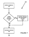
- FIG. 7 is a flowchart illustrating a method for a driver to package a media changer command, in accordance with an exemplary embodiment.
- FIG. 8 is a flowchart illustrating a method for bridging a command to another device, in accordance with an exemplary embodiment.
- the claimed embodiments contemplate systems, apparatuses and methods for processing and delivery of media changer commands through a host and an SATA-type bridging device to a media changer device—in essence, providing for multiple LUN functionality in an SATA device.
- the claimed embodiments take the form of a driver on a host.
- the driver is operative to portray to the host that two peripheral devices are connected when only one actually is. That is, the devices are connected in a serial fashion—host, first device and then second device.
- that first device is an SATA drive and the second device is a media changer system.
- the driver receives a command, determines a command type and packages the command if the command is a media changer system command.
- the host then forwards the command to the SATA drive.
- the command is received, and the drive determines if the command is a media changer command. If it is, the drive bridges the command to the media changer system.
- the claimed embodiments advantageously, are operable to provide multiple LUN functionality in a SATA-type environment.
- FIG. 1 illustrates, for didactic purposes, a hardware system 800 , which can be used to implement portions of the claimed embodiments.
- hardware system 800 includes processor 802 and cache memory 804 coupled to each other as shown.
- hardware system 800 includes high performance input/output (I/O) bus 806 and standard I/O bus 808 .
- Host bridge 810 couples processor 802 to high performance I/O bus 806
- I/O bus bridge 812 couples the two buses 806 and 808 to each other.
- Coupled to bus 806 are network/communication interface 824 , system memory 814 , and video memory 816 .
- display device 818 is coupled to video memory 816 .
- Coupled to bus 808 are mass storage 820 , keyboard and pointing device 822 , and I/O ports 826 .
- Mass storage 820 is used to provide permanent storage for the data and programming instructions to perform the above described functions implemented in the system controller, whereas system memory 814 (e.g., DRAM) is used to provide temporary storage for the data and programming instructions when executed by processor 802 .
- I/O ports 826 are one or more serial and/or parallel communication ports used to provide communication between additional peripheral devices, which may be coupled to hardware system 800 .
- Hardware system 800 may include a variety of system architectures and various components of hardware system 800 may be rearranged.
- cache 804 may be on-chip with processor 802 .
- cache 804 and processor 802 may be packed together as a “processor module”, with processor 802 being referred to as the “processor core”.
- certain implementations of the present invention may not require nor include all of the above components.
- the peripheral devices shown coupled to standard I/O bus 808 may be coupled to high performance I/O bus 806 .
- only a single bus may exist with the components of hardware system 800 being coupled to the single bus.
- additional components may be included in system 800 , such as additional processors, storage devices, or memories.
- the operations of the claimed embodiments are implemented as a series of software routines run by hardware system 800 .
- the hardware system 800 is configured to implement the driver stack illustrated in FIG. 6 .
- These software routines comprise a plurality or series of instructions to be executed by a processor in a hardware system, such as processor 802 .
- the series of instructions are stored on a storage device, such as mass storage 820 .
- the series of instructions can be stored on any suitable storage medium, such as a diskette, CD-ROM, ROM, etc.
- the series of instructions need not be stored locally, and could be received from a remote storage device, such as a server on a network, via network/communication interface 824 .
- the instructions are copied from the storage device, such as mass storage 820 , into memory 814 and then accessed and executed by processor 802 .
- the claimed embodiments are implemented in discrete hardware or firmware.
- FIG. 1 illustrates, for didactic purposes, a typical hardware architecture
- the claimed embodiments can be implemented on a wide variety of computer system architectures, such as network-attached servers, laptop computers, and the like.
- An operating system manages and controls the operation of system 800 , including the input and output of data to and from software applications (not shown).
- the operating system provides an interface, such as a graphical user interface (GUI), between the user and the software applications being executed on the system.
- GUI graphical user interface
- the operating system is the Windows® 95/98/NT/XP operating system, available from Microsoft Corporation of Redmond, Wash.
- the claimed embodiments may be used with other operating systems, such as the Apple Macintosh Operating System, available from Apple Computer Inc. of Cupertino, Calif., UNIX operating systems, LINUX operating systems, and the like.
- FIG. 2 illustrates a typical automated data storage library 10 which can be used in conjunction with the claimed embodiments.
- FIG. 3 illustrates a detailed internal view of a frame ( 11 , 12 , 13 ) of the automatic data storage library 10 of FIG. 2 .
- the library is arranged for accessing data storage media (not shown) in response to commands from at least one external host system (not shown) such as system 800 , and comprises storage shelves 16 on a front wall 17 and a rear wall 19 for storing data storage media.
- the library 10 further comprises at least one data storage drive 15 for reading and/or writing data with respect to the data storage media and at least one robot accessor 18 for transporting the data storage media between the storage shelves 16 and the data storage drive(s) 15 .
- the data storage drives 15 may be optical disk drives or magnetic tape drives and the data storage media may comprise optical or magnetic tape media, respectively, or any other removable media associated with corresponding drives.
- the library 10 may also comprise an operator panel 23 or other user interface, such as a web-based interface, which allows a user to interact with the library 10 . Additionally, a control port (not shown) may be provided, which permits communications between a host and the library, e.g., for receiving commands from a host and forwarding the commands to the library, but which is possibly not a data storage drive.
- the library 10 may comprise one or more frames 11 , 12 and 13 , each having storage shelves 16 accessible by the robot accessor 18 .
- the robot accessor 18 comprises a gripper assembly 20 for gripping one or more data storage media and may also include a bar code scanner 22 or other reading system, such as a smart card reader, mounted on the gripper 20 to “read” identifying information about the data storage media.
- FIG. 4 represents a typical, computing environment for explaining principles of the claimed embodiments.
- a host computer 120 including at least a central processing unit (CPU) 122 and a main memory 124 , communicates with peripheral computing equipment via an interface bus structure 26 , which may be a broad-band parallel or serial bi-directional path, or other suitable interconnection.
- Peripherals may include a hard disk drive 30 , other devices 32 , such as printers, terminals, etc., and a tape drive 34 .
- the tape drive 34 includes a tape drive/host interface circuit 36 for connecting the tape drive 34 to the bus structure 26 .
- the tape drive 34 also includes a data compressor circuit 38 operating in accordance with a conventional data compression and compaction algorithm, such as Lempel-Zev, type 1 (LZ1).
- the tape drive 34 includes a suitably sized cache buffer memory 40 , which in this example may be a four megabyte solid state random access memory array including an array controller (not separately shown).
- the tape drive 34 includes a programmed microcontroller 42 for controlling the various circuit elements and processes as more fully explained hereinafter.
- the tape drive 34 also includes motor speed, tape tensioning, and head positioning servo circuitry 44 , and a data read/write electronics channel 46 leading to a head structure 48 within a tape transport mechanism 50 (which is shown in FIG. 1 to be separated by dashed lines from the rest of the electronics circuitry of the tape drive 34 ).
- Magnetic recording tape 152 supplied from e.g. a single feed reel cartridge 154 , is spooled onto an internal take up reel 156 after having passed sinuously around a plurality of tape guide rollers 58 and past the head structure 48 .
- an automatic tape buckling mechanism not shown and not particularly pertinent to an understanding of the present invention, enables coupling of the tape from the cartridge 154 to a leader attached to the take up reel 156 .
- the tape drive/host interface 36 is connected to the head structure 48 via an internal data path 164 which includes the data compressor 38 , the cache buffer 40 and the read/write circuitry 46 .
- an internal data path 164 which includes the data compressor 38 , the cache buffer 40 and the read/write circuitry 46 .
- two control nodes 166 and 168 span the data compressor 38 within the data path 164 and are interconnected by a bypass path 70 , the function of which will be explained in greater detail hereinafter.
- the microcontroller 42 is connected to an internal control bus structure 162 which enables the microcontroller 42 to monitor and control the tape drive/host interface circuit 36 , the data compressor 38 , the cache buffer 40 , the servos circuitry 44 , and the read/write channel electronics 46 .
- the microcontroller 42 also controls the two control nodes 166 and 168 spanning the data compressor 38 . It will therefore be appreciated that a user data record incoming from the host computer 120 (or disk drive 30 ) may be passed directly into the data compressor 38 and then into the cache buffer 40 in compressed format, or the data record may be passed directly into the cache buffer 40 without being compressed, in accordance with the states of the control nodes 166 and 168 spanning the data compressor 38 within the internal data path 164 . Also, it should be appreciated that some process latency exists within the data compressor 38 , so that some time elapses from the time an un-encoded user data record enters the compressor 38 until compressed data derived from the user data record completes exiting out of the compressor.
- tape drive 34 can utilize removable media such as a tape cassette. It should additionally be noted that the claimed embodiments can be practiced with other removable media such as a CD drive, a DVD drive, a floppy drive, an optical drive, etc.
- FIG. 5 is a block diagram illustrating a host system 500 connected to an automation device 510 in which aspects of the claimed embodiments may operate.
- Host system 500 is similar to system 800 of FIG. 1
- SATA drive 520 is similar to drive 34 of FIG. 4
- automation device, of which drive 520 is part of, is similar to automated data storage library 10 of FIGS. 2-3 .
- Automation device further includes an automation device controller 530 , robotics 540 and magazine 550 . Also included are I/O ports ( 560 and 570 ), bridge controller 600 and various connections ( 610 , 620 and 630 ).
- SATA drive 520 is enabled with LUN functionality. Therefore, automation device commands generated from system 500 can be bridged through drive 520 to the automation device controller 530 .
- drive 520 is separate from automation device 510 .
- FIG. 6 is a block diagram illustrating a driver stack 640 , in accordance with an exemplary embodiment. Included in stack 640 are numerous drivers. Mini port driver 650 and port driver 660 are kernel-mode drivers, specific to an individual device or piece of hardware that is linked to the Windows Driver Model. Typically, either the mini port driver 650 or the port driver 660 will be employed in transmitting commands to drive 520 . The decision on which one to use depends on hardware configuration. For example, if SATA hardware is located on a daughterboard contained in system 500 , then the mini port driver 650 will typically be used. If SATA hardware is located on a motherboard contained in system 500 , then the port driver 660 will typically be employed.
- Filter driver 670 is placed on top of the port drivers ( 650 , 660 ) and is operable to present drive 520 and automation device controller 530 to host system 500 as two separately attached devices even though automation device controller 530 is not directly linked to system 500 .
- filter driver 670 emulates two devices and presents two sets (LUN 0 , LUN 1 ) of SCSI command set layers and class drivers to system 500 .
- a first set for the drive 520 is LUN 0 and includes SCSI command set layer 680 and class driver 690 .
- LUN 1 for the library/automation device controller 530 includes SCSI command set layer 700 and class driver 710 .
- filter driver 670 To ensure that filter driver 670 is able to present two devices to system 500 , it can be loaded twice, for example, at system 500 's startup through two entries in system 500 's registry. As system 500 goes through device discovery, the two entries of filter driver 670 will be loaded. Alternatively, filter driver 670 could present itself as two instances of port drivers. In such an implementation, the filter driver 670 maintains state information to make sure it registers both devices with the operating system at boot up to ensure that higher layer drivers are loaded. Of course, there are other methods for device driver 670 to present two devices to system 500 and the claimed embodiments are not necessarily limited to the preceding examples.
- FIG. 7 is a flowchart illustrating a method 720 for a driver to package a media changer command, in accordance with an exemplary embodiment.
- Method 720 describes how the filter driver 670 , loaded on the system 500 , identifies a media changer command and packages the media command for bridging by the automated storage system. Initially, the driver 720 receives a command ( 730 ) and determines if it is a media changer command ( 740 ). If yes, the driver packages the media changer command for appropriate routing ( 750 ).
- filter driver 670 distinguishes between commands received from the upper layer drivers 690 , 710 corresponding to the drive and the library (media changer), respectively.
- commands received from class driver 710 are packaged or modified for bridging by the SATA Drive 520 , while commands received from class driver 690 are forwarded without addition of an opcode (see below) or other indicator.
- filter driver 670 then forwards the command ( 760 ) to port driver 660 for processing. Eventually, a command is transmitted to SATA drive 520 .
- Packaging the media changer command can be accomplished in a variety of ways.
- the media changer command is encoded with an operational code (“opcode”) instruction and compressed.
- opcode operational code
- an opcode is inserted in the command, for example at the first byte, and the command is strobed to the SATA drive 520 .
- the first byte, with the opcode indicates to the SATA drive 520 that a media changer command is coming through and the balance of the command is then sent in a serial manner.
- the value of the opcode can be any suitable value recognized by the storage system controller.
- FIG. 8 is a flowchart illustrating a method 770 for bridging a command to another device, in accordance with an exemplary embodiment.
- Method 770 describes how the SATA drive 520 handles a command received from the system 500 .
- the drive 520 determines if the received command is a media changer command (in one implementation, by detecting the opcode added by the filter driver 670 of the host system). If it is, the command is bridged to a media changer device.
- the drive 520 receives a command ( 780 ).
- the drive 520 makes a determination ( 790 ) to see if it is a media changer/bridge to library command. If yes, the drive 520 sends the command ( 800 ) to the automation device controller 530 . Otherwise, the drive 520 processes the command, forwarding the command to the next driver layer of the drive 520 ( 810 ).
Landscapes
- Engineering & Computer Science (AREA)
- Theoretical Computer Science (AREA)
- Physics & Mathematics (AREA)
- General Engineering & Computer Science (AREA)
- General Physics & Mathematics (AREA)
- Human Computer Interaction (AREA)
- Stored Programmes (AREA)
Abstract
Description
Claims (20)
Priority Applications (1)
| Application Number | Priority Date | Filing Date | Title |
|---|---|---|---|
| US11/443,824 US7600059B2 (en) | 2006-05-31 | 2006-05-31 | Multiple LUN support for SATA devices |
Applications Claiming Priority (1)
| Application Number | Priority Date | Filing Date | Title |
|---|---|---|---|
| US11/443,824 US7600059B2 (en) | 2006-05-31 | 2006-05-31 | Multiple LUN support for SATA devices |
Publications (2)
| Publication Number | Publication Date |
|---|---|
| US20080127222A1 US20080127222A1 (en) | 2008-05-29 |
| US7600059B2 true US7600059B2 (en) | 2009-10-06 |
Family
ID=39465449
Family Applications (1)
| Application Number | Title | Priority Date | Filing Date |
|---|---|---|---|
| US11/443,824 Active 2027-01-24 US7600059B2 (en) | 2006-05-31 | 2006-05-31 | Multiple LUN support for SATA devices |
Country Status (1)
| Country | Link |
|---|---|
| US (1) | US7600059B2 (en) |
Citations (7)
| Publication number | Priority date | Publication date | Assignee | Title |
|---|---|---|---|---|
| US6574696B1 (en) | 2000-03-07 | 2003-06-03 | Hewlett-Packard Development Company, L.P. | Methods and arrangements for providing bi-directional control between data storage drives and automation controllers |
| US6925519B2 (en) | 2002-07-25 | 2005-08-02 | Lsi Logic Corporation | Automatic translation from SCSI command protocol to ATA command protocol |
| US20050226059A1 (en) * | 2004-02-11 | 2005-10-13 | Storage Technology Corporation | Clustered hierarchical file services |
| US20060107016A1 (en) * | 2004-11-12 | 2006-05-18 | Akira Murotani | Storage device and storage device data life cycle control method |
| US7082483B2 (en) * | 2002-05-13 | 2006-07-25 | Trek Technology (Singapore) Pte. Ltd. | System and apparatus for compressing and decompressing data stored to a portable data storage device |
| US7146476B2 (en) * | 2003-08-05 | 2006-12-05 | Sepaton, Inc. | Emulated storage system |
| US20060282194A1 (en) * | 2005-06-10 | 2006-12-14 | Bdt Ag | Tape library storage bridge |
-
2006
- 2006-05-31 US US11/443,824 patent/US7600059B2/en active Active
Patent Citations (7)
| Publication number | Priority date | Publication date | Assignee | Title |
|---|---|---|---|---|
| US6574696B1 (en) | 2000-03-07 | 2003-06-03 | Hewlett-Packard Development Company, L.P. | Methods and arrangements for providing bi-directional control between data storage drives and automation controllers |
| US7082483B2 (en) * | 2002-05-13 | 2006-07-25 | Trek Technology (Singapore) Pte. Ltd. | System and apparatus for compressing and decompressing data stored to a portable data storage device |
| US6925519B2 (en) | 2002-07-25 | 2005-08-02 | Lsi Logic Corporation | Automatic translation from SCSI command protocol to ATA command protocol |
| US7146476B2 (en) * | 2003-08-05 | 2006-12-05 | Sepaton, Inc. | Emulated storage system |
| US20050226059A1 (en) * | 2004-02-11 | 2005-10-13 | Storage Technology Corporation | Clustered hierarchical file services |
| US20060107016A1 (en) * | 2004-11-12 | 2006-05-18 | Akira Murotani | Storage device and storage device data life cycle control method |
| US20060282194A1 (en) * | 2005-06-10 | 2006-12-14 | Bdt Ag | Tape library storage bridge |
Non-Patent Citations (3)
| Title |
|---|
| 'Shared Storage Model'. SNIA Technical Council [online]. Apr. 13, 2003. [retrieved on Mar. 6, 2006]. Retrieved from the Internet: <URL: http://www.snia.org/tech-activities/shared-storage-model/SNIA-SSM-text-2003-04-13.pdf>. |
| Strange, John. 'New Storage Stack Architecture-Cobra'. Microsoft Corporation [online]. 2004. [retrieved on Mar. 6, 2006]. Retrieved from the Internet: <URL: http://download.microsoft.com/download/1/8/f/18f8cee2-0b64-41f2-893d-a6f22954b40c8/DW4025-WINHEC2004.ppt>. |
| 'The Mass Storage Driver Stack'. Apple Computer Developer Connection [online]. Dec. 6, 2005. [retrieved on Mar. 6, 2006]. Retrieved from the Internet: <URL: http://developer.apple.com/documentation/DeviceDrivers/Conceptual/MassStorage/02-Overview/chapter-2-section-4.html>. |
Also Published As
| Publication number | Publication date |
|---|---|
| US20080127222A1 (en) | 2008-05-29 |
Similar Documents
| Publication | Publication Date | Title |
|---|---|---|
| US8046187B2 (en) | Test systems for media drives of data storage systems | |
| US7831575B2 (en) | Library virtualisation module | |
| US8966174B2 (en) | Storage system | |
| US8898394B2 (en) | Data migration method | |
| JP5159901B2 (en) | Method for facilitating I / O processing for input / output (I / O) operations in a host computer system configured to communicate with a controller | |
| US20060282194A1 (en) | Tape library storage bridge | |
| US7643410B2 (en) | Method and apparatus for managing a connection in a connection orientated environment | |
| US20080010400A1 (en) | Method and apparatus for automatically determining optimal access time of hard disk | |
| EP1308955B1 (en) | Electronic data library system | |
| EP1760578A1 (en) | Storage system and storage control method | |
| US8065466B2 (en) | Library apparatus, library system and method for copying logical volume to disk volume in cache disk with smallest access load | |
| US6973516B1 (en) | Method and apparatus for a controller capable of supporting multiple protocols | |
| EP1785867A2 (en) | Method and apparatus for verifying data in a storage system | |
| US8661237B2 (en) | System and method for booting a plurality of servers from a shared boot image stored on a USB boot image sharer | |
| US20050149645A1 (en) | Storage control device | |
| US7774560B2 (en) | Storage emulator and method thereof | |
| US20070198773A1 (en) | Data storage drive for automated data storage library | |
| US20080005362A1 (en) | SATA odd block handling | |
| TW434491B (en) | Increasing I/O performance through storage of packetized operational information in local memory | |
| US11226756B2 (en) | Indirect storage data transfer | |
| US7600059B2 (en) | Multiple LUN support for SATA devices | |
| US20060277326A1 (en) | Data transfer system and method | |
| US20070127322A1 (en) | Apparatus system and method for managing control path commands in an automated data storage library | |
| US8667188B2 (en) | Communication between a computer and a data storage device | |
| US20070214311A1 (en) | Homogeneous device initialization of data storage library subsystems which may have heterogeneous devices |
Legal Events
| Date | Code | Title | Description |
|---|---|---|---|
| AS | Assignment |
Owner name: QUANTUM CORPORATION, CALIFORNIA Free format text: ASSIGNMENT OF ASSIGNORS INTEREST;ASSIGNORS:WONG, JIM;AWEIDA, OSAMA;MATTHEWS, DON;REEL/FRAME:017947/0229 Effective date: 20060530 |
|
| AS | Assignment |
Owner name: CREDIT SUISSE, NEW YORK Free format text: SECURITY AGREEMENT;ASSIGNORS:QUANTUM CORPORATION;ADVANCED DIGITAL INFORMATION CORPORATION;CERTANCE HOLDINGS CORPORATION;AND OTHERS;REEL/FRAME:019605/0159 Effective date: 20070712 Owner name: CREDIT SUISSE,NEW YORK Free format text: SECURITY AGREEMENT;ASSIGNORS:QUANTUM CORPORATION;ADVANCED DIGITAL INFORMATION CORPORATION;CERTANCE HOLDINGS CORPORATION;AND OTHERS;REEL/FRAME:019605/0159 Effective date: 20070712 |
|
| STCF | Information on status: patent grant |
Free format text: PATENTED CASE |
|
| AS | Assignment |
Owner name: QUANTUM INTERNATIONAL, INC., WASHINGTON Free format text: RELEASE BY SECURED PARTY;ASSIGNOR:CREDIT SUISSE, CAYMAN ISLANDS BRANCH (FORMERLY KNOWN AS CREDIT SUISSE), AS COLLATERAL AGENT;REEL/FRAME:027968/0007 Effective date: 20120329 Owner name: WELLS FARGO CAPITAL FINANCE, LLC, AS AGENT, CALIFO Free format text: SECURITY AGREEMENT;ASSIGNOR:QUANTUM CORPORATION;REEL/FRAME:027967/0914 Effective date: 20120329 Owner name: CERTANCE (US) HOLDINGS, INC., WASHINGTON Free format text: RELEASE BY SECURED PARTY;ASSIGNOR:CREDIT SUISSE, CAYMAN ISLANDS BRANCH (FORMERLY KNOWN AS CREDIT SUISSE), AS COLLATERAL AGENT;REEL/FRAME:027968/0007 Effective date: 20120329 Owner name: CERTANCE, LLC, WASHINGTON Free format text: RELEASE BY SECURED PARTY;ASSIGNOR:CREDIT SUISSE, CAYMAN ISLANDS BRANCH (FORMERLY KNOWN AS CREDIT SUISSE), AS COLLATERAL AGENT;REEL/FRAME:027968/0007 Effective date: 20120329 Owner name: ADVANCED DIGITAL INFORMATION CORPORATION, WASHINGT Free format text: RELEASE BY SECURED PARTY;ASSIGNOR:CREDIT SUISSE, CAYMAN ISLANDS BRANCH (FORMERLY KNOWN AS CREDIT SUISSE), AS COLLATERAL AGENT;REEL/FRAME:027968/0007 Effective date: 20120329 Owner name: CERTANCE HOLDINGS CORPORATION, WASHINGTON Free format text: RELEASE BY SECURED PARTY;ASSIGNOR:CREDIT SUISSE, CAYMAN ISLANDS BRANCH (FORMERLY KNOWN AS CREDIT SUISSE), AS COLLATERAL AGENT;REEL/FRAME:027968/0007 Effective date: 20120329 Owner name: QUANTUM CORPORATION, WASHINGTON Free format text: RELEASE BY SECURED PARTY;ASSIGNOR:CREDIT SUISSE, CAYMAN ISLANDS BRANCH (FORMERLY KNOWN AS CREDIT SUISSE), AS COLLATERAL AGENT;REEL/FRAME:027968/0007 Effective date: 20120329 |
|
| FPAY | Fee payment |
Year of fee payment: 4 |
|
| AS | Assignment |
Owner name: TCW ASSET MANAGEMENT COMPANY LLC, AS AGENT, MASSACHUSETTS Free format text: SECURITY INTEREST;ASSIGNOR:QUANTUM CORPORATION;REEL/FRAME:040451/0183 Effective date: 20161021 Owner name: TCW ASSET MANAGEMENT COMPANY LLC, AS AGENT, MASSAC Free format text: SECURITY INTEREST;ASSIGNOR:QUANTUM CORPORATION;REEL/FRAME:040451/0183 Effective date: 20161021 |
|
| AS | Assignment |
Owner name: PNC BANK, NATIONAL ASSOCIATION, PENNSYLVANIA Free format text: SECURITY INTEREST;ASSIGNOR:QUANTUM CORPORATION;REEL/FRAME:040473/0378 Effective date: 20161021 Owner name: QUANTUM CORPORATION, CALIFORNIA Free format text: RELEASE BY SECURED PARTY;ASSIGNOR:WELLS FARGO CAPITAL FINANCE, LLC, AS AGENT;REEL/FRAME:040474/0079 Effective date: 20161021 |
|
| FPAY | Fee payment |
Year of fee payment: 8 |
|
| AS | Assignment |
Owner name: U.S. BANK NATIONAL ASSOCIATION, AS AGENT, OHIO Free format text: SECURITY INTEREST;ASSIGNORS:QUANTUM CORPORATION, AS GRANTOR;QUANTUM LTO HOLDINGS, LLC, AS GRANTOR;REEL/FRAME:049153/0518 Effective date: 20181227 Owner name: QUANTUM CORPORATION, CALIFORNIA Free format text: RELEASE BY SECURED PARTY;ASSIGNOR:TCW ASSET MANAGEMENT COMPANY LLC, AS AGENT;REEL/FRAME:047988/0642 Effective date: 20181227 |
|
| AS | Assignment |
Owner name: PNC BANK, NATIONAL ASSOCIATION, PENNSYLVANIA Free format text: SECURITY INTEREST;ASSIGNOR:QUANTUM CORPORATION;REEL/FRAME:048029/0525 Effective date: 20181227 |
|
| MAFP | Maintenance fee payment |
Free format text: PAYMENT OF MAINTENANCE FEE, 12TH YEAR, LARGE ENTITY (ORIGINAL EVENT CODE: M1553); ENTITY STATUS OF PATENT OWNER: LARGE ENTITY Year of fee payment: 12 |
|
| AS | Assignment |
Owner name: BLUE TORCH FINANCE LLC, AS AGENT, NEW YORK Free format text: SECURITY INTEREST;ASSIGNORS:QUANTUM CORPORATION;QUANTUM LTO HOLDINGS, LLC;REEL/FRAME:057107/0001 Effective date: 20210805 |
|
| AS | Assignment |
Owner name: QUANTUM CORPORATION, CALIFORNIA Free format text: RELEASE BY SECURED PARTY;ASSIGNOR:U.S. BANK NATIONAL ASSOCIATION;REEL/FRAME:057142/0252 Effective date: 20210805 Owner name: QUANTUM LTO HOLDINGS, LLC, CALIFORNIA Free format text: RELEASE BY SECURED PARTY;ASSIGNOR:U.S. BANK NATIONAL ASSOCIATION;REEL/FRAME:057142/0252 Effective date: 20210805 |