US759865A - Sandpapering-machine. - Google Patents
Sandpapering-machine. Download PDFInfo
- Publication number
- US759865A US759865A US15444003A US1903154440A US759865A US 759865 A US759865 A US 759865A US 15444003 A US15444003 A US 15444003A US 1903154440 A US1903154440 A US 1903154440A US 759865 A US759865 A US 759865A
- Authority
- US
- United States
- Prior art keywords
- gage
- shaft
- clamp
- drum
- angle
- Prior art date
- Legal status (The legal status is an assumption and is not a legal conclusion. Google has not performed a legal analysis and makes no representation as to the accuracy of the status listed.)
- Expired - Lifetime
Links
Images


Classifications
-
- B—PERFORMING OPERATIONS; TRANSPORTING
- B24—GRINDING; POLISHING
- B24B—MACHINES, DEVICES, OR PROCESSES FOR GRINDING OR POLISHING; DRESSING OR CONDITIONING OF ABRADING SURFACES; FEEDING OF GRINDING, POLISHING, OR LAPPING AGENTS
- B24B27/00—Other grinding machines or devices
- B24B27/0076—Other grinding machines or devices grinding machines comprising two or more grinding tools
Definitions
- My invention has relation to sandpaperingmachines, more especially such as may be used in the manufacture of patterns and that class of work; and the object is to provide a sandpapering-machine which can be adapted to nearly every surface for finishing or polishing wood or metal patterns.
- leading features of the invention conor other roughenedsurfaces and a table adapted to be adjusted at any angle with reference to the disk and to hold the work in operative relation to the disk at any such adjustment.
- 1t also consists in the means attached to the table for the bringing into position and holding circular, cylindrical, cone, and conic shaped bodies and the like, whereby they may be operated upon by the sandpapering-disk, and in providing a gage for the purpose of assisting in operating upon square or angular work.
- drum or cylinder covered with sandpaper and in the appliances for holding work whereby the drum may be conveniently adapted to operate upon the centers and the insides of cylindrical and other concave surfaces.
- Fig. 5 is a front elevation of the disk and attach- Fig. 6 is a plan view of the table with ments.
- Fig. 7 is a vertical section of the table and of the clamping device for the slide in the table with part cut away.
- Fig. 8 is a perspective view of the gage for the drum and the device for setting the gage at an angle to the drum.
- Fig. 9 is a detail of the supporting-plate of the angle-bracket.
- Fig. l() is a perspective view in detail of one of the operating-levers.
- Fig. 11 is a perspective view of the machine with table turned down.
- Fig. 12 is a detail of part of the appliances for operating the gage for the drum.
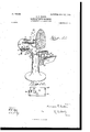
- 2 designates the frame, which is preferably of cylindrical shape and spreading at the base, through which it may be secured to the floor.
- the upper end terminates in two arms 3 and .4, which provide the bearings fora shaft 5 and also the usual lubricating-boxes 1 for the shaft.
- a driving-pulley 6 which is beltedfto the power.
- adisk 8 Upon one end of the shaft outside of the arm 3 is fastened adisk 8, and upon the saine shaft outside of the arm 4 is secured a drum 9.- I The disk 8 and the drum 9 are supplied withsandpaper, emery, or otherwise roughened. Against the opposite sides of the frame are secured the lugs or plates and 12. To the plate 1() is attached the appliances for operating a gage 14 and to the plate 12 means for operating atable 15.
- brace35 For the purpose of additionally sustaining the table at right ang'les to the disk 8 there is hinged to the end of the shaft 21 a brace35,
- a slide 55 (see Figs. 6 and 7 in which a pin 56 is set, preferably near one end.
- This slide is held by a thumbscrew 58, which engages a tapering bolt 60, passing' through the table. Between this bolt and the slide is The manner of use of this pin is as follows: The Work is pressed down on this pin 56, which acts as a pivot for the work, and the thumb-screw 58 is turned, drawing down the bolt 60 and crowding the slide 61 against the slide 55, and thus holdingthe slide 55 firmly in the groove.
- a gage 14 which is preferably of the shape shown in Figs. 3 and 8.
- a square bar 68 is secured in the gage at right angles to it, and around the bar is a clamp 70, pro# vided with outwardly projecting lugs 71, through which passes a screw 72.
- This scr'ew is operated by a lever 75, pivoted in the head of the screw in a similar manner to the screw 30 and the lever 42. This permits the gage to be moved along the drum and set an any position relative to the drum.
- the gage 14 For the purpose of adjusting the gage 14 to an angle to the drum there is adjustably fas tened tothe plate 1() another plate, 78, provided with a slot 8() and held adjustably by a screw 81.
- the plate is provided with two arms 82, which project upwardly, and on their top is cast a plate 84.
- a right-angle plate 86 On the top of the plate 84 is a right-angle plate 86, in which is a slot 88 and a bolt 89, provided with a nut passing through the slot 88 and also through a plate 90, subsequently to be described, and holds adjustably the gage 14.
- Beneath the plate 84 is another plate, 90, which is slotted at 92, and at one end are lugs 93, adapted to enga-ge the end of the plate 84.
- a cam 95 In the slot 92 'is pivoted a cam 95, having a handle 96 for operating the same,
- the plate 86 is preferably cast integral with the clamp 70.
- the screw 72 is IOO released by the lever 75, and this releases the p clamp upon the shaft 68, and the shaft, with the gage attached, is slid along in the clamp 70 to the point desired or may be withdrawn entirely from the clamp.
- the bolt 89 is released by lifting the handle 96 and turning the cam 95. This permits the plate 86 to be moved long'itudinally or turned at any angle on the bolt 89, and in this manner the gage is also turned to anyangle to the drum.
- gage 14 may be set at any position along the drum and at right angles to it cylinders having their ends at right angles to the plane of their surfaces can be readily operated upon in their inner sides by inserting the drum within the cylinder and pressing the end of the cylinder against the gage. It will also be seen that since the gage may be set at any angle to the drum cylinders or concave surfaces which have ends cut at any angle other than a right angle to the plane of its surface may be readily oper- IIO ated'upon by simply turning the gage 14 to correspond to the angle of the ends of the concave surfaces and operating as before.
- a frame In a sandpapering-machine, a frame, a shaft, a cylindrical sanded surface adapted to rotate with the shaft, a gage substantially as described and shovvn, and means for setting and holding the gage at any position along the sanded surface or at an angle to it.
- a frame In a sandpapering-machine, a frame, a shaft journaled in the frame, a sanded surface adapted to be rotated by the said shaft, a gage, means for setting the gage in operative relation along the sanded surface consisting of a shaft attached to the gage a clamp on the shaft and a lever for operating the clamp.
- a frame In a sandpapering-machine, a frame, a shaft journaled in the frame, a cylindrical sanded surface adapted to be rotated with the shaft, a gage 14, curved at its inner edge to shaft journaled in the frame, a cylindrical sanded surface adapted to rotate with the shaft, and a gage 14 adapted to be set at any position along the sanded surface and at an angle to it consisting of arms attached to the frame, a plate 84, a plate 86 adjustably attached to the arms,- a clamp attached to the plate 86, a shaft engaging said clamp to which the gage is attached and a lever for operating said clamp.
Description
Nofvses. PATENTED MAY 17, 1904.
N. P. coLLls.
SANDPAPERING MACHINE.
APPLwATloN FILED APR. 27, 190s. No MODEL. a sums-SHEET 1.
Jwwm@ @mmm '60 PATENTBD MAY 17, 1904.
Y N. P. GOLLIS. SANDPAPERING MACHINE.
APPLICATION FILED APB.. 27, 1903.
3 SHEETS--SHEET 2 NO MODEL.
5 wu@ what )www @a @www wifhwmm,
W WL bmi? Hoang No. 759,865. v PATENTED MAY 17, 1904.` N. P. GGLLIS.
SANDIAPERING MACHINE.
APPLICATION FILED APR. 27, 1903.
No MODEL. s SHEETS-slums.
www (a gangli);
fr i uw@ @mi m: nonms Putas no. uom-mma. wnsmuaromp. c.
Patented May 1'?, 1904.
UNITED STATES PATENT OFFICE.
' NORMAN r. ooLLIs, OE DUBUOUE, IOWA.
SANDPAFERING-MACHINE.
SPECIFICATION forming part of Letters Patent No. I759,865, dated May 1'?, 1904.
Application filed April 27, 1903. Serial No. IMA/i0. (No model.)
To @ZZ whom it may concern:
Beit known that I, NORMAN P. CoLLIs, a citizen of the United States, residing inthe city and county of Dubuque and State of Iowa, have invented certain new and useful Improvements in Sandpapering-Machines; and I do hereby declare the following to be a full, clear, and exact description of the invention, which will enable others skilled in the art-to which it appertains to make and use the same.
My invention has relation to sandpaperingmachines, more especially such as may be used in the manufacture of patterns and that class of work; and the object is to provide a sandpapering-machine which can be adapted to nearly every surface for finishing or polishing wood or metal patterns.
sist in a disk upon which is placed sandpaper The leading features of the invention conor other roughenedsurfaces and a table adapted to be adjusted at any angle with reference to the disk and to hold the work in operative relation to the disk at any such adjustment.
1t also consists in the means attached to the table for the bringing into position and holding circular, cylindrical, cone, and conic shaped bodies and the like, whereby they may be operated upon by the sandpapering-disk, and in providing a gage for the purpose of assisting in operating upon square or angular work.
It further consists in a drum or cylinder covered with sandpaper and in the appliances for holding work whereby the drum may be conveniently adapted to operate upon the centers and the insides of cylindrical and other concave surfaces.
The nature and operation of my improve- Inents will be readily understood by all conversant with such matters after the following cx'planation, when taken and read in connec- `tion with the drawings accompanying the section through the line A A of Fig. 1. Fig. 5 is a front elevation of the disk and attach- Fig. 6 is a plan view of the table with ments.
slide and gage. Fig. 7 is a vertical section of the table and of the clamping device for the slide in the table with part cut away. Fig. 8 is a perspective view of the gage for the drum and the device for setting the gage at an angle to the drum. Fig. 9 is a detail of the supporting-plate of the angle-bracket. Fig. l() is a perspective view in detail of one of the operating-levers. Fig. 11 is a perspective view of the machine with table turned down. Fig. 12 is a detail of part of the appliances for operating the gage for the drum.
Like figures of reference denote corresponding parts in each of the drawings.
Referring to the drawings, 2 designates the frame, which is preferably of cylindrical shape and spreading at the base, through which it may be secured to the floor. The upper end terminates in two arms 3 and .4, which provide the bearings fora shaft 5 and also the usual lubricating-boxes 1 for the shaft. Between the arms on the shaft is secured a driving-pulley 6, which is beltedfto the power.
Upon one end of the shaft outside of the arm 3 is fastened adisk 8, and upon the saine shaft outside of the arm 4 is secured a drum 9.- I The disk 8 and the drum 9 are supplied withsandpaper, emery, or otherwise roughened. Against the opposite sides of the frame are secured the lugs or plates and 12. To the plate 1() is attached the appliances for operating a gage 14 and to the plate 12 means for operating atable 15.
For the purpose of operating the table 15 there is attached to the plate 12 two parallel arms 20, which project out at nearly right angles to the frame, and on their outer ends is secured a shaft 2l, around which is secured a clamp 22, provided with arms 25. In the top of the arms is pinned a round shaft 26, around which is secured a clamp 28, having lugs or ears 27 and tothe top of the clamp is fastened a table 15 by the screws 29. Through the outer ends of the clamp is inserted a screw 30 to hold the clamp by friction on` the shaft 21. For the purpose of operating this screw, whereby the table may be turned away from the disk, in the screw-head 32 is pivoted a swivel-handle or operating-lever 42, adapted a slide 61.
to be raised and lowered vertically or turned to operate the screw 30. By this mode of attaching the table it may be turned entirely away from the disk by simply loosening' the screw by the lever 42 and turning the table down, as shown in Fig. 11.
Whenever it is desired to adjust the table at an angle to the disk or sanded surface 8, there is inserted through the' ears 27 of the clamp 28 a screw 40, in the head of which is pivoted a lever or swivel-handle 33 and operated in the same manner as the screw 30 is operated by the lever 42. In this manner by loosening the screw by the lever 33 the table may be adjusted at an angle, and then by the lever 33 the screw 40 is drawn up and holds the table at such an adjusted angle.
For the purpose of additionally sustaining the table at right ang'les to the disk 8 there is hinged to the end of the shaft 21 a brace35,
which may be brought up and engage the under edge 36 of the table. -When it is desired to use the table at an angle to the disk, as shown by the dotted lines in Fig. 2, it will be seen that if the brace 35 is removed and the clamp 28 loosened and the outer edge of the table pressed down at that ang'le the edge next to the disk would be thrown considerably away from the disk and too far for successfully operating the work, and to avoid this and to have the table assume the position as shown in dotted lines, with the edge 45 in its proper relation to the disk, there is attached upon the clamp 22 a lug 48. (Shown in Figs. 2 and 4.) Between the two arms 2O is secured a bracket by a screwl. Upon the bracket is fastened a slide 52, on which the lug 48 rests or engages the top of the slide when the table is at right angles to the disk, as shown in full lines in Fig'. 2; but when the table is tipped to an angle this slide 52 is withdrawn, and the lug 48 will move down past the slide 52 and will allow the table to be tipped and the edge of the table assume the position shown in dotted llnes, with the edge 45 in proper relation to the disk for operating upon the work effectively.
When it is desired to operate upon the outside of cylinders, cones, or concave surfaces, there is set in a groove in the face of the table 15 a slide 55, (see Figs. 6 and 7 in which a pin 56 is set, preferably near one end. This slide is held by a thumbscrew 58, which engages a tapering bolt 60, passing' through the table. Between this bolt and the slide is The manner of use of this pin is as follows: The Work is pressed down on this pin 56, which acts as a pivot for the work, and the thumb-screw 58 is turned, drawing down the bolt 60 and crowding the slide 61 against the slide 55, and thus holdingthe slide 55 firmly in the groove.
Upon the table is pivoted a gage 62 by the pivot-pin 64, adapted to be set at any angle bythe set-screw 65 in the slot 66.
For the purpose of operating upon the drum 9, whereby the inside of cylinders, concave surfaces, and the like are finished, there is provided a gage 14, which is preferably of the shape shown in Figs. 3 and 8. A square bar 68 is secured in the gage at right angles to it, and around the bar is a clamp 70, pro# vided with outwardly projecting lugs 71, through which passes a screw 72. This scr'ew is operated by a lever 75, pivoted in the head of the screw in a similar manner to the screw 30 and the lever 42. This permits the gage to be moved along the drum and set an any position relative to the drum.
For the purpose of adjusting the gage 14 to an angle to the drum there is adjustably fas tened tothe plate 1() another plate, 78, provided with a slot 8() and held adjustably by a screw 81. The plate is provided with two arms 82, which project upwardly, and on their top is cast a plate 84. On the top of the plate 84 is a right-angle plate 86, in which is a slot 88 and a bolt 89, provided with a nut passing through the slot 88 and also through a plate 90, subsequently to be described, and holds adjustably the gage 14.
Beneath the plate 84 is another plate, 90, which is slotted at 92, and at one end are lugs 93, adapted to enga-ge the end of the plate 84. In the slot 92 'is pivoted a cam 95, having a handle 96 for operating the same, The plate 86 is preferably cast integral with the clamp 70.
In operating the gage 14 it is set as shown in Figs. l, 3, and 8, with the inner edge nearly to the surface of the drum, and the lever 75 is turned, drawing' up the screw 72, which closes the clamp 70 on the bar or shaft 68, and the gage will then be rigidly held where it is set.
When it is desired to change the'position of the gage along vthe drum, the screw 72 is IOO released by the lever 75, and this releases the p clamp upon the shaft 68, and the shaft, with the gage attached, is slid along in the clamp 70 to the point desired or may be withdrawn entirely from the clamp. l
WV hen it is desired to vary the angle of the gage to the drum, the bolt 89 is released by lifting the handle 96 and turning the cam 95. This permits the plate 86 to be moved long'itudinally or turned at any angle on the bolt 89, and in this manner the gage is also turned to anyangle to the drum.
It is manifest that since the gage 14 may be set at any position along the drum and at right angles to it cylinders having their ends at right angles to the plane of their surfaces can be readily operated upon in their inner sides by inserting the drum within the cylinder and pressing the end of the cylinder against the gage. It will also be seen that since the gage may be set at any angle to the drum cylinders or concave surfaces which have ends cut at any angle other than a right angle to the plane of its surface may be readily oper- IIO ated'upon by simply turning the gage 14 to correspond to the angle of the ends of the concave surfaces and operating as before.
With this construction and operation of the sanded surfaces, together with the manipulation of the table and gages, there will rarely be found a surface which cannot be operated upon, and not necessarily by an expert.
Having now described my invention, what I claim is- 1. In a sandpapering-machine, a frame, a shaft, a cylindrical sanded surface adapted to rotate with the shaft, a gage substantially as described and shovvn, and means for setting and holding the gage at any position along the sanded surface or at an angle to it. i
2. In a sandpapering-machine, a frame, a shaft journaled in the frame, a sanded surface adapted to be rotated by the said shaft, a gage, means for setting the gage in operative relation along the sanded surface consisting of a shaft attached to the gage a clamp on the shaft and a lever for operating the clamp.
3. In a sandpapering-machine, a frame, a shaft journaled in the frame, a cylindrical sanded surface adapted to be rotated with the shaft, a gage 14, curved at its inner edge to shaft journaled in the frame, a cylindrical sanded surface adapted to rotate with the shaft, and a gage 14 adapted to be set at any position along the sanded surface and at an angle to it consisting of arms attached to the frame, a plate 84, a plate 86 adjustably attached to the arms,- a clamp attached to the plate 86, a shaft engaging said clamp to which the gage is attached and a lever for operating said clamp.
In testimony whereof I have signed my name to this specification in the presence of two subscribing Witnesses.
NORMAN P. COLLIS.
Witnesses:
M. M. CADY, A. GENGLER.
Priority Applications (1)
| Application Number | Priority Date | Filing Date | Title |
|---|---|---|---|
| US15444003A US759865A (en) | 1903-04-27 | 1903-04-27 | Sandpapering-machine. |
Applications Claiming Priority (1)
| Application Number | Priority Date | Filing Date | Title |
|---|---|---|---|
| US15444003A US759865A (en) | 1903-04-27 | 1903-04-27 | Sandpapering-machine. |
Publications (1)
| Publication Number | Publication Date |
|---|---|
| US759865A true US759865A (en) | 1904-05-17 |
Family
ID=2828354
Family Applications (1)
| Application Number | Title | Priority Date | Filing Date |
|---|---|---|---|
| US15444003A Expired - Lifetime US759865A (en) | 1903-04-27 | 1903-04-27 | Sandpapering-machine. |
Country Status (1)
| Country | Link |
|---|---|
| US (1) | US759865A (en) |
Cited By (3)
| Publication number | Priority date | Publication date | Assignee | Title |
|---|---|---|---|---|
| US2741073A (en) * | 1953-09-08 | 1956-04-10 | Schwabe Herman | Shoe upper roughing machine |
| US3071889A (en) * | 1959-04-08 | 1963-01-08 | Silver Julian | Convertible wood type machine shop toy |
| US20030092366A1 (en) * | 2001-11-15 | 2003-05-15 | New Tech S.R.L. | Tubular workpiece notching machine usable for general grinding operations |
-
1903
- 1903-04-27 US US15444003A patent/US759865A/en not_active Expired - Lifetime
Cited By (3)
| Publication number | Priority date | Publication date | Assignee | Title |
|---|---|---|---|---|
| US2741073A (en) * | 1953-09-08 | 1956-04-10 | Schwabe Herman | Shoe upper roughing machine |
| US3071889A (en) * | 1959-04-08 | 1963-01-08 | Silver Julian | Convertible wood type machine shop toy |
| US20030092366A1 (en) * | 2001-11-15 | 2003-05-15 | New Tech S.R.L. | Tubular workpiece notching machine usable for general grinding operations |
Similar Documents
| Publication | Publication Date | Title |
|---|---|---|
| US2889757A (en) | Machine tool vise | |
| US1528536A (en) | Woodworking machinery | |
| US2726693A (en) | Fixture clamp with pivotally mounted actuating screw | |
| US759865A (en) | Sandpapering-machine. | |
| US2436152A (en) | Portable flange serrating tool | |
| US2349087A (en) | Work clamp | |
| GB607188A (en) | Improvements in or relating to angle measuring devices | |
| US2768485A (en) | Drill grinding fixture | |
| US1741923A (en) | Screw clamp | |
| US1282022A (en) | Lens-slotting machine. | |
| US466303A (en) | Schied | |
| US871053A (en) | Cutter-head setter. | |
| US3378001A (en) | Diamond dressing device | |
| US1992147A (en) | Workholder | |
| US1046296A (en) | Holder for templet-gages for setting cutters in cutter-heads. | |
| US2771723A (en) | Radius grinding fixture | |
| US2683385A (en) | Sharpening device with angular and longitudinal adjustments | |
| US837112A (en) | Plate or negative squaring machine. | |
| US1295982A (en) | Device for positioning tools to be dressed. | |
| US2515877A (en) | Cam-operated pivoted-jaw clamp having plural positions for cam and jaw fulcrums | |
| US223315A (en) | Waltbe s | |
| US481737A (en) | Work-holder for boring-machines | |
| US2328826A (en) | Clearance angle radius dressing attachment for surface grinding machines | |
| US1394392A (en) | Apparatus for edging tiles and the like | |
| US2498892A (en) | Slidably and tiltably adjustable bench dog |