US7597531B2 - Method of controlling mover device - Google Patents
Method of controlling mover device Download PDFInfo
- Publication number
- US7597531B2 US7597531B2 US11/044,632 US4463205A US7597531B2 US 7597531 B2 US7597531 B2 US 7597531B2 US 4463205 A US4463205 A US 4463205A US 7597531 B2 US7597531 B2 US 7597531B2
- Authority
- US
- United States
- Prior art keywords
- base
- processing
- movable base
- processing base
- movable
- Prior art date
- Legal status (The legal status is an assumption and is not a legal conclusion. Google has not performed a legal analysis and makes no representation as to the accuracy of the status listed.)
- Expired - Fee Related, expires
Links
Images


Classifications
-
- G—PHYSICS
- G05—CONTROLLING; REGULATING
- G05D—SYSTEMS FOR CONTROLLING OR REGULATING NON-ELECTRIC VARIABLES
- G05D3/00—Control of position or direction
- G05D3/12—Control of position or direction using feedback
-
- H10P72/3202—
-
- G—PHYSICS
- G05—CONTROLLING; REGULATING
- G05D—SYSTEMS FOR CONTROLLING OR REGULATING NON-ELECTRIC VARIABLES
- G05D13/00—Control of linear speed; Control of angular speed; Control of acceleration or deceleration, e.g. of a prime mover
- G05D13/02—Details
-
- H10P72/30—
-
- H10P72/3204—
-
- H10P72/50—
-
- Y—GENERAL TAGGING OF NEW TECHNOLOGICAL DEVELOPMENTS; GENERAL TAGGING OF CROSS-SECTIONAL TECHNOLOGIES SPANNING OVER SEVERAL SECTIONS OF THE IPC; TECHNICAL SUBJECTS COVERED BY FORMER USPC CROSS-REFERENCE ART COLLECTIONS [XRACs] AND DIGESTS
- Y10—TECHNICAL SUBJECTS COVERED BY FORMER USPC
- Y10S—TECHNICAL SUBJECTS COVERED BY FORMER USPC CROSS-REFERENCE ART COLLECTIONS [XRACs] AND DIGESTS
- Y10S414/00—Material or article handling
- Y10S414/135—Associated with semiconductor wafer handling
Definitions
- the present invention generally relates to methods of controlling mover devices, cooperative devices of the mover devices, cooperative methods of the mover devices, semiconductor manufacturing devices, liquid crystal manufacturing devices, and mechanical scan ion implantation devices.
- the present invention is related to a method of controlling a mover device causing a moving force when a processing base reciprocates at high speed, an cooperative device of the mover device, an cooperative method of the mover device, a semiconductor manufacturing device having the cooperative device, a liquid crystal manufacturing device having the cooperative device, and a mechanical scan ion implantation device having the cooperative device.
- a sputtering process for physically forming a thin film on a substrate
- a CVD sputtering process for forming a thin film on a substrate through chemical vapor deposition
- a lithography process for processing the shape of a thin film formed on a substrate
- an impurity adding process for adding impurities to a film formed on a substrate
- an etching process for etching a thin film formed on a substrate
- an electronic beam process for performing minute processing on the surface of a substrate, using electronic beams
- an ion beam process for performing minute processing on the surface of a substrate, using ion beams
- an ion implanting process for implanting ions, using ion beams
- a testing process for conducting a test on a substrate
- an exposure process to be carried out to form a pattern on a substrate.
- a processor to carry out each of the processes is equipped with a mover device that accurately moves a stage (a processing base) within a processing chamber or a vacuum processing chamber at high speed. Each substrate is attached to the stage (the processing base) prior to an operation.
- processing is performed on the entire area of the substrate. Therefore, it is necessary to repeatedly move and stop the processing base in one direction, or to reciprocate the processing base throughout the operation or in a part of the operation.
- a mover device that exhibits a higher stopping accuracy, moves at a higher speed, and has a processing base with a higher performance normally has a greater mass than a conventional mover device.
- greater driving reaction forces are generated from accelerating, decelerating, starting, reversing, and stopping movements of the processing base of such a mover device.
- a mover device with a higher performance tends to have a heaver processing base. This also causes greater driving reaction forces.
- conventional methods of preventing driving reaction force generation cannot effectively restrict undesirable impact, vibration, and noise in a mover device.
- a general object of the present invention is to provide methods of controlling mover devices, cooperative devices of the mover devices, cooperative methods of the mover devices, semiconductor manufacturing devices, liquid crystal manufacturing devices, and mechanical scan ion implantation devices in which the above disadvantages are eliminated.
- a more specific object of the present invention is to provide a method of controlling a mover device, an cooperative device of the mover device, an cooperative method of the mover device, a semiconductor manufacturing device, a liquid crystal manufacturing device, and a mechanical scan ion implantation device, in which a processing base can reciprocate at high speed without undesirable impact, vibration, and noise.
- a method of controlling a mover device that includes: a fixed base; a movable base that is moveable in a linear direction with respect to the fixed base; a processing base that is movable in a linear direction with respect to the movable base, the linear direction being in parallel with the linear moving direction of the movable base; and a moving force generating unit that is provided between the processing base and the movable base, and forms a main moving unit in cooperation with the processing base and the movable base,
- the method including the steps of:
- the mover base may be moveable in the linear direction with respect to the fixed base by a second linear support guide;
- the processing base that may be moveable in the linear direction with respect to the movable base by a first linear support guide
- the mover device may include a first precise relative position measuring unit that is provided between the processing base and the fixed base, and a second precise relative position measuring unit that is provided between the movable and the fixed base;
- the processing base may move with respect to the fixed base by virtue of a moving force acting in the opposite direction as a result of the movement of the processing base with respect to the movable base;
- the moving velocity of the processing base with respect to the fixed base may be controlled by using a detection signal generated from the first precise relative position measuring unit;
- the processing base may be supported by the first linear guide so as to move with respect to the fixed base;
- the movable base may be supported by the second linear guide so as to move with respect to the processing base.
- the processing base may be supported by the first linear guide so as to move with respect to the fixed base
- the movable base may be supported by the second linear guide so as to move with respect to the fixed base.
- the reaction force caused by the accelerating or decelerating movement of the processing base is absorbed by the movable base, and does not reach the fixed base. Accordingly, even when the processing base is moved at high speed, undesirable vibration is not caused in the mover device at the times of acceleration and deceleration of the processing base. Thus, the processing base can be stably moved with high precision.
- a method of controlling a mover device that includes: a fixed base; a movable base that is moveable in a linear direction with respect to the fixed base; a processing base that is movable in a linear direction with respect to the movable base, the linear direction being in parallel with the linear moving direction of the movable base; and a moving force generating unit that is provided between the processing base and the movable base, and forms a main moving unit in cooperation with the processing base and the movable base,
- Disturbance correction controls of the movable base and the processing base may be independently performed by the moving force generating unit and the auxiliary driving unit.
- the movable base and the processing base may be controlled so that moving time of acceleration and deceleration motions and a uniform velocity motion of the processing base and the movable base is same and constant.
- the movable base and the processing base may be set so that moving time of acceleration and deceleration motions and a uniform velocity motion of the processing base and the movable base is same and constant by a position-time control;
- the movable base and the processing base may be driven by a control whereby the movable base and the processing base are synchronized in intervals of the acceleration and deceleration motions and the uniform velocity motion.
- the reaction force caused by the acceleration or deceleration movement of the processing base can be completely absorbed. Also, cogging force generation can be prevented.
- the auxiliary driving unit can smoothly move the processing base and the movable base with high precision. Furthermore, the moving velocity of the processing base can be adjusted to a predetermined uniform velocity promptly, and the processing base can be stopped promptly. Accordingly, the uniform velocity region can be widened.
- the processing base and the movable base change moving states at the same time (for example, from an accelerating state to a uniform velocity moving state), the processing base and the movable base can interact with each other so as to prevent a positional deviation.
- the velocity controlling unit may control the processing base to reciprocate in a predetermined range.
- the velocity controlling unit may control the processing base to reciprocate in a predetermined range in such a manner that the processing base moves in both directions at the same velocity in each uniform velocity reciprocation movement.
- the velocity controlling unit may repeat acceleration control, uniform velocity control, and deceleration control, while moving the processing base with respect to the fixed base.
- the mover device further includes a first belt connecting one end and the other end of the processing base, and a second belt connecting one end and the other end of the movable base;
- the first and second belts are connected by pulley step parts for the processing base and the movable base, the pulley step parts including two-step pulleys provided one at each end part of the fixed base;
- the pulley step parts are formed as pulley steps whose corresponding diameters for an inverse ratio of the ratio of masses of the processing base and the movable base;
- the first belt and the second belt wind around the pulley step parts in opposite directions.
- an cooperative device of a mover device that includes: a fixed base; a movable base that is moved in a linear direction with respect to the fixed base by a second linear support guide; a processing base that is moved in a linear direction with respect to the movable base by a first linear support guide, the linear direction being in parallel with the linear moving direction of the movable base; a first precise relative position measuring unit that is provided between the processing base and the fixed base; a second precise relative position measuring unit that is provided between the movable base and the fixed base; and a moving force generating unit that is provided between the processing base and the movable base, and forms a main moving unit in cooperation with the processing base and the movable base;
- the movable base is moved on the fixed base in the opposite direction to the moving direction of the processing base by virtue of a reaction force caused by the moving force generated from the moving force generating unit to move the processing base, so that the movable base moves in the opposite direction to the moving direction of the processing base on the fixed base;
- the moving velocity of the processing base with respect to the fixed base is controlled, using a detection signal generated from the first precise relative position measuring unit;
- the mover device further includes a first belt connecting one end and the other end of the processing base, and a second belt connecting one end and the other end of the movable base;
- the first and second belts are connected by pulley step parts for the processing base and the movable base, the pulley step parts including two-step pulleys provided one at each end part of the fixed base;
- the pulley step parts are formed as pulley steps whose corresponding diameters form an inverse ratio of the ratio of masses of the processing base and the movable base;
- the first belt connecting both ends of the processing base and the second belt connecting both ends of the movable base wind around the pulley step parts in opposite directions. Accordingly, even when the processing base is moved at high speed, undesirable vibration is not caused in the mover device at the times of acceleration and deceleration of the processing base. Thus, the processing base can be stably moved with high precision.
- the processing base and the movable base may be driven by a fluid actuator using fluid as transfer means.
- the processing base and the movable base are driven by the fluid actuator using fluid as the transfer means, even when the processing base is moved at high speed, undesirable vibration is not caused in the mover device at the times of acceleration and deceleration of the processing base.
- the processing base can be stably moved with high precision.
- An excess tension adjust member may be provided at both ends of the processing base and both ends of the movable base so as to adjust excess tension between the first belt and the second belt.
- the excess tension adjust member is provided at the first and second belts, the tensions acting at the first and second belts are absorbed by the excess tension adjust member. Accordingly, even when the processing base is moved at high speed, undesirable vibration is not caused in the mover device at the times of acceleration and deceleration of the processing base. Thus, the processing base can be stably moved with high precision.
- An adjustment mechanism may be provided so as to adjust tensions of the first belt and the second belt.
- the adjustment mechanism is provided so as to adjust tensions of the first belt and the second belt, the tensions acting at the first and second belts are properly adjusted. Accordingly, even when the processing base is moved at high speed, undesirable vibration is not caused in the mover device at the times of acceleration and deceleration of the processing base. Thus, the processing base can be stably moved with high precision.
- the cooperative device of the mover device may further include:
- processing base may be moved with respect to the movable base by the moving force generation unit.
- the actuator is provided to rotate two-step pulleys, and the processing base is moved with respect to the movable base by the moving force generation unit. Accordingly, even when the processing base is moved at high speed, undesirable vibration is not caused in the mover device at the times of acceleration and deceleration of the processing base. Thus, the processing base can be stably moved with high precision.
- the cooperative device including the mover device may be provided in a vertical state
- the processing base and the movable base may be moved in a vertical direction.
- the processing base can be stably moved with high precision.
- a semiconductor manufacturing device having an cooperative device including a mover device that includes: a fixed base; a movable base that is moved in a linear direction with respect to the fixed base by a second linear support guide; a processing base that is moved in a linear direction with respect to the movable base by a first linear support guide, the linear direction being in parallel with the linear moving direction of the movable base; a first precise relative position measuring unit that is provided between the processing base and the fixed base; a second precise relative position measuring unit that is provided between the movable base and the fixed base; and a moving force generating unit that is provided between the processing base and the movable base, and forms a main moving unit in cooperation with the processing base and the movable base;
- a moving force is generated from the moving force generating unit to move the processing base with respect to the movable base, thereby the processing base is moved with respect to the fixed base by virtue of a moving force acting in the opposite direction as a result of the movement of the processing base with respect to the movable base;
- the movable base is moved on the fixed base in the opposite direction to the moving direction of the processing base by virtue of a reaction force caused by the moving force generated from the moving force generating unit to move the processing base, so that the movable base moves in the opposite direction to the moving direction of the processing base on the fixed base;
- the moving velocity of the processing base with respect to the fixed base is controlled, using a detection signal generated from the first precise relative position measuring unit;
- the mover device further includes a first belt connecting one end and the other end of the processing base, and a second belt connecting one end and the other end of the movable base;
- the first and second belts are connected by pulley step parts for the processing base and the movable base, the pulley step parts including two-step pulleys provided one at each end part of the fixed base;
- the pulley step parts are formed as pulley steps whose corresponding diameters form an inverse ratio of the ratio of masses of the processing base and the movable base;
- the first belt and the second belt wind around the pulley step parts in opposite directions.
- this semiconductor manufacturing device it is possible to implant ions in the wafer as a processed substrate with high precision.
- a liquid crystal device having an cooperative device including a mover device that includes: a fixed base; a movable base that is moved in a linear direction with respect to the fixed base by a second linear support guide; a processing base that is moved in a linear direction with respect to the movable base by a first linear support guide, the linear direction being in parallel with the linear moving direction of the movable base; a first precise relative position measuring unit that is provided between the processing base and the fixed base; a second precise relative position measuring unit that is provided between the movable base and the fixed base; and a moving force generating unit that is provided between the processing base and the movable base, and forms a main moving unit in cooperation with the processing base and the movable base;
- a moving force is generated from the moving force generating unit to move the processing base with respect to the movable base, thereby the processing base is moved with respect to the fixed base by virtue of a moving force acting in the opposite direction as a result of the movement of the processing base with respect to the movable base;
- the movable base is moved on the fixed base in the opposite direction to the moving direction of the processing base by virtue of a reaction force caused by the moving force generated from the moving force generating unit to move the processing base, so that the movable base moves in the opposite direction to the moving direction of the processing base on the fixed base;
- the moving velocity of the processing base with respect to the fixed base is controlled, using a detection signal generated from the first precise relative position measuring unit;
- the mover device further includes a first belt connecting one end and the other end of the processing base, and a second belt connecting one end and the other end of the movable base;
- the first and second belts are connected by pulley step parts for the processing base and the movable base, the pulley step parts including two-step pulleys provided one at each end part of the fixed base;
- the pulley step parts are formed as pulley steps whose corresponding diameters form an inverse ratio of the ratio of masses of the processing base and the movable base;
- the first belt and the second belt wind around the pulley step parts in opposite directions.
- this crystal liquid manufacturing device it is possible to implant ions in the liquid crystal substrate as a processed substrate with high precision.
- a one-axis mechanical scan ion implantation device having an cooperative device including a mover device that includes: a fixed base; a movable base that is moved in a linear direction with respect to the fixed base by a second linear support guide; a processing base that is moved in a linear direction with respect to the movable base by a first linear support guide, the linear direction being in parallel with the linear moving direction of the movable base; a first precise relative position measuring unit that is provided between the processing base and the fixed base; a second precise relative position measuring unit that is provided between the movable base and the fixed base; and a moving force generating unit that is provided between the processing base and the movable base, and forms a main moving unit in cooperation with the processing base and the movable base;
- a moving force is generated from the moving force generating unit to move the processing base with respect to the movable base, thereby the processing base is moved with respect to the fixed base by virtue of a moving force acting in the opposite direction as a result of the movement of the processing base with respect to the movable base;
- the moving velocity of the processing base with respect to the fixed base is controlled, using a detection signal generated from the first precise relative position measuring unit;
- the mover device further includes a first belt connecting one end and the other end of the processing base, and a second belt connecting one end and the other end of the movable base;
- the first and second belts are connected by pulley step parts for the processing base and the movable base, the pulley step parts including two-step pulleys provided one at each end part of the fixed base,
- the pulley step parts are formed as pulley steps whose corresponding diameters form an inverse ratio of the ratio of masses of the processing base and the movable base, and
- the first belt and the second belt wind around the pulley step parts in opposite directions.
- this one-axis mechanical scan ion implantation device it is possible to implant ions in the processed substrate with high precision.
- a two-axis mechanical scan ion implantation device having an cooperative device including a mover device that includes: a fixed base; a movable base that is moved in a linear direction with respect to the fixed base by a second linear support guide; a processing base that is moved in a linear direction with respect to the movable base by a first linear support guide, the linear direction being in parallel with the linear moving direction of the movable base; a first precise relative position measuring unit that is provided between the processing base and the fixed base; a second precise relative position measuring unit that is provided between the movable base and the fixed base; and a moving force generating unit that is provided between the processing base and the movable base, and forms a main moving unit in cooperation with the processing base and the movable base;
- a moving force is generated from the moving force generating unit to move the processing base with respect to the movable base, thereby the processing base is moved with respect to the fixed base by virtue of a moving force acting in the opposite direction as a result of the movement of the processing base with respect to the movable base;
- the movable base is moved on the fixed base in the opposite direction to the moving direction of the processing base by virtue of a reaction force caused by the moving force generated from the moving force generating unit to move the processing base, so that the movable base moves in the opposite direction to the moving direction of the processing base on the fixed base;
- the moving velocity of the processing base with respect to the fixed base is controlled, using a detection signal generated from the first precise relative position measuring unit;
- the mover device further includes a first belt connecting one end and the other end of the processing base, and a second belt connecting one end and the other end of the movable base;
- the first and second belts are connected by pulley step parts for the processing base and the movable base, the pulley step parts including two-step pulleys provided one at each end part of the fixed base,
- the pulley step parts are formed as pulley steps whose corresponding diameters form an inverse ratio of the ratio of masses of the processing base and the movable base, and
- the first belt and the second belt wind around the pulley step parts in opposite directions.
- the moving force generating unit may perform asynchronous driving so as to shift timings of pulse driving of the main moving device and pulse driving of the auxiliary driving unit to achieve non-driving interference.
- the moving force generating unit performs asynchronous driving so as to shift the timings of pulse driving of the main moving device and pulse driving of the auxiliary driving unit to achieve non-driving interference, even when the processing base is moved at high speed, undesirable vibration is not caused in the mover device at the times of acceleration and deceleration of the processing base.
- the processing base can be stably moved with high precision.
- the auxiliary driving unit may be provided between the fixed base and the movable base;
- the movable base with respect to the fixed base may be controlled by the auxiliary driving unit so as to have a uniform velocity in a uniform velocity control interval by driving of the moving force generating unit of the processing base;
- a gap of the movable base against the fixed base may be adjusted by the auxiliary driving unit in the acceleration and deceleration intervals.
- the gap of the movable base against the fixed base is adjusted by the auxiliary driving unit in the acceleration and deceleration intervals.
- a method of controlling a mover device that includes: a fixed base; a movable base that is moved in a linear direction with respect to the fixed base by a second linear support guide; a processing base that is moved in a linear direction with respect to the movable base by a first linear support guide, the linear direction being in parallel with the linear moving direction of the movable base; a first precise relative position measuring unit that is provided between the processing base and the fixed base; a second precise relative position measuring unit that is provided between the movable base and the fixed base; and a moving force generating unit that is provided between the processing base and the movable base, and forms a main moving unit in cooperation with the processing base and the movable base;
- the method including the steps of:
- processing base with respect to the movable base is velocity-controlled by a detection signal of a third precise relative position measuring unit provided between the processing base and the movable base;
- a moving velocity of the processing base with respect to the fixed base in the uniform velocity region is correction-controlled by the first precise relative position measuring unit.
- the processing base with respect to the movable base is velocity-controlled by the detection signal of the third precise relative position measuring unit provided between the processing base and the movable base, and the moving velocity of the processing base with respect to the fixed base in the uniform velocity region is correction-controlled by the first precise relative position measuring unit. Accordingly, even when the processing base is moved at high speed, undesirable vibration is not caused in the mover device at the times of acceleration and deceleration of the processing base. Thus, the processing base can be stably moved with high precision.
- starting friction, dynamic friction, and actual driving torque diagram of the movable base and the processing base may be preliminarily calculated
- the moving force generating unit may be controlled by a preliminary correction trapezoid so that the processing base has a uniform velocity with respect to the fixing base.
- the starting friction, dynamical friction, and actual driving torque diagram of the movable base and the processing base are preliminarily calculated, and the moving force generating unit is controlled by the preliminary correction trapezoid so that the processing base has a uniform velocity with respect to the fixed base. Hence, it is possible to reciprocate the processing base more stably.
- the movable base and the processing base may be reciprocated designated times in advance, so that moving data obtained from the preliminary reciprocation are sampled,
- main sampling correction trapezoid data may be obtained from the data having been sampled
- the moving force generating unit may be program-controlled so that the velocity of the processing base has a uniform velocity with respect to the fixed base.
- the movable base and the processing base are reciprocated designated times in advance, so that moving data obtained from the preliminary reciprocation are been sampled, the main sampling correction trapezoid data are obtained from the data having been sampled, and the moving force generating unit is program-controlled so that the processing base has a uniform velocity with respect to the fixed base. Accordingly, even when the processing base is moved at high speed, undesirable vibration is not caused in the mover device at the times of acceleration and deceleration of the processing base. Thus, the processing base can be stably moved with high precision.
- FIG. 1A is a left side view of a mover device in accordance with a first embodiment of the present invention
- FIG. 1B is a plan view of the mover device in accordance with the first embodiment
- FIG. 1C is a right side view of the mover device in accordance with the first embodiment
- FIG. 1D is a section view of the mover device, taken along the line A-A of FIG. 1B ;
- FIG. 1E is a section view of the mover device, taken along the line B-B of FIG. 1B ;
- FIG. 1F is a section view of the mover device, taken along the line C-C of FIG. 1B ;
- FIG. 2A is a plan view of the fixed base of the mover device in accordance with the first embodiment
- FIG. 2B is a right side view of the fixed base of the mover device in accordance with the first embodiment
- FIG. 2C is a front view of the fixed base of the mover device in accordance with the first embodiment
- FIG. 3A is a plan view of the movable base of the mover device in accordance with the first embodiment
- FIG. 3B is a right side view of the movable base of the mover device in accordance with the first embodiment
- FIG. 3C is a section view of the movable device, taken along the line A-A of FIG. 3A ;
- FIG. 4A is a plan view of the processing base of the mover device in accordance with the first embodiment
- FIG. 4B is a right side view of the processing base of the mover device in accordance with the first embodiment
- FIG. 4C is a front view of the processing base of the mover device in accordance with the first embodiment
- FIGS. 5A through 5H illustrate the center of composite gravity between the processing base and the movable base
- FIG. 6 is a control block diagram of the mover device in accordance with the first embodiment of the present invention.
- FIG. 7 is a flowchart of a movement control operation to be performed on the processing base
- FIG. 8 is a flowchart of an origin return process
- FIG. 9 is a flowchart of an acceleration control process to be carried out for the processing base
- FIG. 10 is a flowchart of an acceleration control process to be carried out for the movable base
- FIG. 11 is a flowchart of a uniform velocity control process to be carried out for the processing base
- FIG. 12 is a flowchart of a uniform velocity control process to be carried out for the movable base
- FIG. 13 is a flowchart of a deceleration control process to be carried out for the processing base
- FIG. 14 is a flowchart of a deceleration control process to be carried out for the movable base
- FIG. 15 is a flowchart of a deviation correcting process to be carried out for the movable base
- FIG. 16 is a flowchart of a deviation correcting process to be carried out for the processing base
- FIG. 17 shows examples of the velocity setting trapezoids of the processing base and the movable base
- FIGS. 18A through 18F illustrate the hardware structure of a mover device in accordance with a second embodiment of the present invention
- FIGS. 19A through 19F illustrate the hardware structure of a mover device in accordance with a third of the present invention
- FIGS. 20A through 20C illustrate the hardware structure of a mover device in accordance with a fourth embodiment of the present invention
- FIGS. 21A through 21C illustrate the hardware structure of a mover device in accordance with a fifth embodiment of the present invention
- FIG. 22A is a plan view illustrating the hardware structure of an ion implanter apparatus in accordance with a sixth embodiment of the present invention.
- FIG. 22B is a front view illustrating the ion implanter apparatus in accordance with the sixth embodiment.
- FIG. 22C is a right side view illustrating the ion implanter apparatus in accordance with the sixth embodiment.
- FIG. 23A is a plan view illustrating the hardware structure of an ion implanter apparatus in accordance with a seventh embodiment of the present invention.
- FIG. 23B is a front view illustrating the ion implanter apparatus in accordance with the seventh embodiment.
- FIG. 23C is a right side view illustrating the ion implanter apparatus in accordance with the seventh embodiment.
- FIGS. 24A and 24B illustrate operations of the ion implanter apparatus in accordance with the seventh embodiment
- FIG. 25A is a plan view illustrating the hardware structure of an ion implanter apparatus in accordance with an eighth embodiment of the present invention.
- FIG. 25B is a front view illustrating the ion implanter apparatus in accordance with the eighth embodiment.
- FIG. 25C is a right side view illustrating the ion implanter apparatus in accordance with the eighth embodiment.
- FIG. 26 is a schematic view of details of a structure of a mover device in accordance with a ninth embodiment
- FIG. 27 is a side cross-sectional view of a support structure of a pulley seen from a side;
- FIG. 28A is a left side view of a mover device in accordance with a tenth embodiment
- FIG. 28B is a plan view of the mover device in accordance with the tenth embodiment.
- FIG. 28C is a right side view of the mover device in accordance with the tenth embodiment.
- FIG. 28D is a section view of the mover device, taken along the line A-A of FIG. 28B ;
- FIG. 28E is a section view of the mover device, taken along the line B-B of FIG. 28B ;
- FIG. 28F is a section view of the mover device, taken along the line C-C of FIG. 28B ;
- FIG. 29A is a left side view of a mover device in accordance with an eleventh embodiment
- FIG. 29B is a plan view of the mover device in accordance with the eleventh embodiment.
- FIG. 29C is a right side view of the mover device in accordance with the eleventh embodiment.
- FIG. 29D is a section view of the mover device, taken along the line A-A of FIG. 29B ;
- FIG. 29E is a section view of the mover device, taken along the line B-B of FIG. 29B ;
- FIG. 29F is a section view of the mover device, taken along the line C-C of FIG. 29B ;
- FIG. 30 is an enlarged view of a structure of two-step pulleys in the eleventh embodiment.
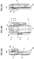
- FIG. 31A is a left side view of a mover device in accordance with a twelfth embodiment
- FIG. 31B is a plan view of the mover device in accordance with the twelfth embodiment.
- FIG. 31C is a right side view of the mover device in accordance with the twelfth embodiment.
- FIG. 31D is a section view of the mover device, taken along the line A-A of FIG. 31B ;
- FIG. 31E is a section view of the mover device, taken along the line B-B of FIG. 31B ;
- FIG. 31F is a section view of the mover device, taken along the line C-C of FIG. 31B ;
- FIG. 32 is an enlarged view of a structure of two-step pulley in the twelfth embodiment
- FIG. 33A is a left side view of a mover device in accordance with a thirteenth embodiment
- FIG. 33B is a plan view of the mover device in accordance with the thirteenth embodiment.
- FIG. 33C is a right side view of the mover device in accordance with the thirteenth embodiment.
- FIG. 33D is a section view of the mover device, taken along the line A-A of FIG. 33B ;
- FIG. 33E is a section view of the mover device, taken along the line B-B of FIG. 33B ;
- FIG. 33F is a section view of the mover device, taken along the line C-C of FIG. 33B ;
- FIG. 34A is a left side view of a mover device in accordance with a fourteenth embodiment
- FIG. 34B is a plan view of the mover device in accordance with the fourteenth embodiment.
- FIG. 34D is a section view of the mover device, taken along the line A-A of FIG. 34B ;
- FIG. 34F is a section view of the mover device, taken along the line C-C of FIG. 34B ;
- FIG. 35B is a plan view of the mover device in accordance with the fifteenth embodiment.
- FIG. 35C is a right side view of the mover device in accordance with the fifteenth embodiment.
- FIG. 35D is a section view of the mover device, taken along the line A-A of FIG. 35B ;
- FIG. 35E is a section view of the mover device, taken along the line B-B of FIG. 35B ;
- FIG. 35F is a section view of the mover device, taken along the line C-C of FIG. 35B .
- FIGS. 1A through 4C illustrate the hardware structure of a mover device 10 A in accordance with a first embodiment of the present invention.
- FIGS. 1A through 1F illustrate the entire structure of the mover device 10 A.
- FIGS. 2A through 2C illustrate a fixed base 11 A.
- FIGS. 3A through 3C illustrate a movable base 12 A.
- FIGS. 4A through 4C illustrate a processing base 13 A.
- the fixed base 11 A will be first described. As shown in FIGS. 1A through 1F and FIGS. 2A through 2C , the fixed base 11 A has a linear guide block 30 in the vicinity of each of the four corners.
- the linear guide blocks 30 are to be engaged with first linear guide rails 60 formed in the movable base 12 A that will be described later. With the linear guide blocks 30 being engaged with the first linear guide rails 60 , the movable base 12 A can be movable in the directions of the arrows X 1 and X 2 with respect to the fixed base 11 A.
- Sub linear motor magnets 31 that form the sub linear motor 15 are provided at the center left in the fixed base 11 A shown in FIG. 2A .
- the sub linear motor magnets 31 are provided at predetermined intervals, and are divided into two rows, with a space being formed between the two rows.
- a sub linear motor coil unit 56 (provided on the movable base 12 A) that is a part of the sub linear motor 15 is inserted in the space.
- the sub linear motor coil unit 56 is movable in the directions of the arrows X 1 and X 2 .
- the holder board 32 is a board material standing on the fixed base 11 A, and extends in the directions of X 1 and X 2 , as shown in FIG. 2B .
- the F-P linear scale 33 and the F-P overrun detecting pieces 43 are provided on the upper surface of the holder board 32 , as shown in FIGS. 2A and 2C .
- the F-P linear scale 33 extends in the directions of X 1 and X 2 on the upper surface of the holder board 32 .
- the length of the F-P linear scale 33 should be longer than the moving range of the processing base 13 A in the directions of X 1 and X 2 .
- the F-P linear scale 33 has an alternating multi-phase (A, B, . . . Z phases) structure in which high light reflectance parts and low light reflectance parts are alternately arranged at predetermined intervals.
- the F-P linear scale 33 forms a F-P sensor 16 in cooperation with an optical sensor 35 provided on the processing base 13 A.
- the F-P sensor 16 detects the location of the movable base 12 A with respect to the fixed base 11 A.
- the location information as to the movable base 12 A with respect to the fixed base 11 A that is detected by the F-P sensor 16 is sent to the control device 80 (see FIG. 6 ).
- the F-M linear scale 34 extends in the directions of X 1 and X 2 on the upper surface of the fixed base 11 A, and is longer than the moving range of the movable base 12 A in the directions of X 1 and X 2 with respect to the fixed base 11 A.
- the F-M linear scale 34 has a multi-phase (A, B, . . . Z phases) structure in which high light reflectance parts and low light reflectance parts are alternately arranged at predetermined intervals.
- the F-M linear scale 34 having such a structure forms a F-M sensor 17 in cooperation with an optical sensor 37 (shown in FIG. 3C ) provided in the movable base 12 A.
- the pair of F-M overrun detecting pieces 44 are provided at a predetermined distance from each other on the fixed base 11 A. As shown in FIG. 2C , each of the F-M overrun detecting pieces 44 is a bent claw-like piece having an L-shape. The F-M overrun detecting pieces 44 form a F-M overrun sensor 19 in cooperation with a photointerrupter 38 provided in the movable base 12 A.
- the F-M overrun sensor 19 detects a movement of the movable base 12 A outside the predetermined allowable moving range due to an external disturbance or the like. Such a movement of the movable base 12 A will be hereinafter referred to as an overrun.
- the positions of the F-M overrun detecting pieces 44 are restricted within the allowable reciprocation moving range of the movable base 12 A in the directions of X 1 and X 2 .
- the overrun detection information is sent to the control device 80 (see FIG. 6 ).
- the movable base origin detecting sensor 22 detects the location of the movable base 12 A with respect to the fixed base 11 A when the mover device 10 A is activated. Therefore, the control device 80 cannot grasp the current location of the movable base 12 A immediately before and after the mover device 10 A is activated.
- the control device 80 moves the movable base 12 A until the photointerrupter 38 detects the movable base origin mark 45 .
- the control device 80 sets an origin that is to be used in software operations (this origin will be hereinafter referred to as the software origin).
- the F-M sensor 17 (including the F-M linear scale 34 and the optical sensor 37 ) can detect the location of the movable base 12 A with respect to the location of the fixed base 11 A.
- the pair of sideboards 50 is provided at a distance from each other in the directions of the arrows X 1 and X 2 .
- the side connecting bodies 51 are provided on the left side and the right side in FIG. 3A .
- the center part connecting body 52 is provided at the center point between the two sideboards 50 .
- the side connecting body 51 which is provided on the left side in FIG. 3A , has a motor arm that is located at the center with respect to the directions of X 1 and X 2 , and extends to the left in FIG. 3A .
- the motor arm 55 has the sub linear motor coil unit 56 extending downward.
- the sub linear motor coil unit 56 has coils provided therein. These coils are cooled down to a predetermined temperature by a cooling mechanism (not shown), and are capable of generating a strong magnetic field though small in size.
- a linear motor with a core.
- a control operation may be performed to make a correction. If cogging force is generated from a linear motor with a core driven at a uniform velocity, a correcting operation needs to be performed to generate positive acceleration to cancel the cogging force. Since the size of the cogging force generated from the linear motor is a known value, the correcting operation to cancel the cogging force is relatively easy.
- the side connecting body 51 provided on the right side in FIG. 3A has a sensor arm 54 that is located at the center with respect to the directions of the X 1 and X 2 , and extends to the right in FIG. 3A . Also, a cable bearing arm 57 to which the cable bearing 46 B is connected is provided at a location slightly shifted from the location of the sensor arm 54 in the direction of X 2 .
- the center part connecting body 52 has three walls, and main linear motor magnets 53 that form the main linear motor 14 are provided on the inner surfaces of the walls.
- the main linear motor magnets 53 are arranged at predetermined intervals, and are divided into two rows, with a space being formed in between.
- a main linear motor coil unit 74 (provided on the processing base 13 A) that is also a part of the main linear motor 14 is inserted in the space between the two rows of the main linear motor magnets 53 .
- the main linear motor coil unit 74 is movable in the directions of the arrows X 1 and X 2 .
- reverse facilitating magnets 62 are formed on each of the inner surfaces of the two facing sideboards 50 of the movable base 12 A. There are eight reverse facilitating magnets 62 provided on the inner surfaces of the two facing sideboards 50 of the movable base 12 A.
- the reverse facilitating magnets 62 help the processing base 13 A to reverse near an end of the movable base 12 A by virtue of magnetic repulsion. More specifically, when the processing base 13 A reverses in an reciprocation movement, the reverse facilitating magnets 78 exhibit a braking effect, a stopping effect, and a reverse directing effect.
- Each of the side connecting bodies 51 has a first linear guide rail 60 provided at the lower end (on the Z 2 side in FIG. 3C ), and has a second linear guide rail 61 at the upper end (on the Z 1 side in FIG. 3C ).
- the first linear guide rails 60 and the second linear guide rails 61 extend in the directions of the arrows X 1 and X 2 , and are flanked by the pair of sideboards 50 .
- the first linear guide rails 60 are to be engaged with the linear guide blocks 30 provided on the fixed base 11 A. Accordingly, the movable base 12 A moves in the directions of the arrows X 1 and X 2 , being guided by the linear guide blocks 30 and the first linear guide rails 60 . Even in a high speed movement, the movable base 12 A can remain positioned with high precision, and move in a stable state.
- the second linear guide rails 61 are to be engaged with linear guide blocks provided on the processing base 13 A. Accordingly, the processing base 13 A moves in the directions of the arrows X 1 and X 2 , being guided by the second linear guide rails 61 and the linear guide blocks 75 . Even in a high speed movement, the processing base 13 A can remain positioned with high precision, and move in a stable state.
- the P-M linear scale 39 is formed over a longer range than the moving range of the processing base 13 A in the directions of X 1 and X 2 with respect to the movable base 12 A.
- the P-M linear scale 39 has a multi-phase (A, B, . . . Z phases) structure in which high light reflectance parts and low light reflectance parts are alternately arranged at predetermined intervals.
- the P-M linear scale 39 having such a structure forms a P-M sensor 18 in cooperation with an optical sensor 40 (see FIG. 4C ) provided in the processing base 13 A.
- the processing base origin mark 41 is located at the center point of the center part connecting body 52 extending in the directions of X 1 and X 2 in this embodiment.
- the processing base origin mark 41 is a mark (a reflection sheet) that includes only the high reflectance parts of the linear scale.
- the processing base origin mark 41 forms a processing base origin detecting sensor 21 in cooperation with an optical sensor 42 provided in the processing base 13 A.
- the processing base origin detecting sensor 21 detects the location of the processing base 13 A with respect to the movable base 12 A when the mover device 10 A is activated. Therefore, the control device 80 cannot grasp the current location of the processing base 13 A immediately before and after the mover device 10 A is activated.
- the location of the processing base 13 A with respect to the location of the movable base 12 A can be detected from the software origin. Therefore, after the setting of the software origin, the P-M sensor 18 (including the P-M linear scale 39 and the optical sensor 40 ) can detect the location of the processing base 13 A with respect to the location of the movable base 12 A.
- the movement of the processing base 13 A with respect to the fixed base 11 A is also detected by the F-P sensor 16 (including the F-P linear scale 33 and the optical sensor 35 ). It is therefore necessary to set a software origin for the F-P sensor 16 in the same manner as the setting of the software origins for the F-M sensor 17 and the P-M sensor 18 .
- This software origin will be hereinafter referred to as the F-P software origin.
- the F-P software origin is determined through an arithmetic operation. More specifically, the movable base 12 A moves with respect to the fixed base 11 A, and the processing base 13 A moves with respect to the movable base 12 A.
- the software origin of the movable base 12 A with respect to the fixed base 11 A (this origin will be hereinafter referred to as the F-M software origin) and the software origin of the processing base 13 A with respect to the movable base 12 A (this software origin will be hereinafter referred to as the P-M software origin) are set in the above described manner. Accordingly, the F-P software origin can be determined through an arithmetic operation based on the F-M software origin and the P-M software origin.
- the processing base 13 A will be described next. As shown in FIGS. 1A through 1F and FIGS. 4A through 4C , the processing base 13 A includes a housing 70 , a stay frame 71 , a platen 72 , and the main linear motor coil unit 74 .
- the housing 70 has a rectangular shape, with a hollow being formed inside.
- the stay frame 71 stands on the upper part of the housing 70 .
- the platen 72 to which an object to be processed, such as a wafer, is to be attached, is provided at the upper end of the stay frame 71 .
- the platen 72 can be rotated by a platen motor 73 built in the processing base origin mark 41 .
- the main linear motor coil unit 74 As shown in FIG. 4C , the main linear motor coil unit 74 , the optical sensor 40 , and the optical sensor 42 are provided inside the housing 70 .
- the main linear motor coil unit 74 has coils provided therein. The coils are cooled down to a predetermined temperature by a cooling mechanism (not shown), and accordingly, can generate a strong magnetic field.
- the main linear motor 14 moves (or drives) the processing base 13 A in the directions of the arrows X 1 and X 2 with respect to the movable base 12 A.
- the main linear motor 14 is controlled by the controlling device 80 (see FIG. 6 ).
- a linear motor that can linearly reciprocate and can be easily controlled is employed as the moving force generator for the movable base 12 A in this embodiment, highly responsive control operations can be performed through simple processes.
- the main linear motor 14 may be a linear motor with a core.
- the housing 70 has a sensor arm 76 that extends to the right in FIGS. 4A and 4C .
- This sensor arm 76 has the optical sensor 35 and the photointerrupter 36 attached thereto.
- the optical sensor 35 forms the F-P sensor 16 in cooperation with the F-P linear scale 33 .
- the photointerrupter 36 forms the F-P overrun sensor 20 in cooperation with the F-P overrun detecting pieces 43 .
- a cable bearing arm 77 to which the cable bearing 46 A is to be connected is provided at the end of the sensor arm 76 .
- the second linear guide rails 61 provided in the movable base 12 A are engaged with the linear guide blocks 75 provided on the processing base 13 A, so as to guide the processing base 13 A in a linear movement.
- the second linear guide rails 61 can be omitted.
- the housing 70 further has the reverse facilitating magnets 78 .
- the reverse facilitating magnets 78 face the reverse facilitating magnets 62 provided on the sideboards 50 of the movable base 12 A. More specifically, the reverse facilitating magnets 78 face the reverse facilitating magnets 62 in the moving direction of the movable base 12 A.
- the reverse facilitating magnets 62 provided on the sideboards 50 facing each other have the same polarity as the reverse facilitating magnets 78 provided on the housing 70 .
- the reverse facilitating magnets 62 and 78 help the reverse movements in the reciprocating movements of the processing base 13 A. Referring now to FIG. 1B , the reverse helping operation of the reverse facilitating magnets 62 and 78 will be described below.
- the processing base 13 A has reached the limit in the direction of the arrow X 1 , and is about to reverse the moving direction and move in the direction of the arrow X 2 . Under the control of the controlling device 80 that will be described later, the processing base 13 A slows down after the constant movement in the X 1 direction.
- the reverse facilitating magnets 78 provided on the housing 70 approach the reverse facilitating magnets 62 provided on the sideboards 50 (the movable base 12 A). Since the reverse facilitating magnets 62 have the same polarity as the reverse facilitating magnets 78 , repulsion forces are caused between the reverse facilitating magnets 62 and the reverse facilitating magnets 78 . As the processing base 13 A approaches the sideboards 50 , the repulsion forces between the magnets 62 and the magnets 78 gradually increase, and finally push the processing base 13 A in the direction of the arrow X 2 (i.e., the reverse direction).
- FIGS. 5A through 5H the basic operation of the mover device 10 A having the above described structure will be described. Although various control operations are performed by the sub linear motor 15 in an actual moving operation of the processing base 13 A, the following description of the basic operation of the mover device 10 A illustrated in FIGS. 5A through 5H does not involve the sub linear motor 15 , for ease of explanation.
- the mover device 10 A of this embodiment has the movable base 12 A provided movably in the directions of X 1 and X 2 on the fixed base 11 A, and the processing base 13 A provided movably in the directions of X 1 and X 2 on the movable base 12 A.
- the main linear motor 14 drives the processing base 13 A to linearly reciprocate in the directions of X 1 and X 2 with respect to the movable base 12 A.
- the reaction force generated from the moving force of the processing base 13 A does not reach the fixed base 11 A, and is absorbed by the movement of the movable base 12 A.
- the main linear motor 14 overcomes the force to start the movable base 12 A, and moves the processing base 13 A with a greater force than the moving force of the movable base 12 A in the opposite direction.
- the force F 1 that is required to move the movable base 12 A in the directions of X 1 and X 2 with respect to the fixed base 11 A is greater than the force F 2 that is required to move the processing base 13 A in the directions of X 1 and X 2 with respect to the movable base 12 A (F 1 >F 2 ).
- the weight of the processing base 13 A is made lighter than the weight of the movable base 12 A, for example.
- the processing base 13 A can be started with certainty, while the movable base 12 A can also be started.
- FIG. 5A illustrates a situation in which the processing base 13 A and the movable base 12 A are located in the movement center position (indicated by the dashed lines denoted by A in FIG. 5A ).
- the centers of gravity G 1 , G 2 , and G 3 are all located in the movement center position A. More specifically, the center of gravity G 1 of the processing base 13 A, the center of composite gravity G 3 , and the center of gravity G 2 of the movable base 12 A are located in this order, seen from the top in FIG. 5A .
- the center of composite gravity G 3 of the center of gravity G 1 of the processing base 13 A and the center of gravity G 2 of the movable base 12 A remains at the predetermined point over the fixed base 11 A. Accordingly, the fixed base 11 A can be prevented from vibrating due to shifting of the center of composite gravity G 3 . Thus, vibration and noise can be eliminated from the mover device 10 A, and the processing base 13 A can be steadily moved with high precision.
- the center of composite gravity G 3 of the center of gravity G 1 of the processing base 13 A and the center of gravity G 2 of the movable base 12 A is substantially the same as a composite application point at which the main linear motor 14 and the sub linear motor 15 cooperate to apply a moving force to the processing base 13 A.
- FIG. 5E illustrates a situation in which the processing base 13 A and the movable base 12 A are located in the movement center position (indicated by the dashed lines denoted by A in FIG. 5E ).
- the centers of gravity G 1 , G 2 , and G 3 are all located at the same point.
- FIG. 5F illustrates a situation in which the processing base 13 A has moved in the X 2 direction.
- the processing base 13 A has moved in the X 2 direction
- the movable base 12 A has moved in the X 1 direction by the reaction force, as shown in FIG. 5F .
- the acceleration in the movement is inversely proportional to the mass ratio of the processing base 13 A to the movable base 12 A.
- the center of gravity G 1 of the processing base 13 A and the center of gravity G 2 of the movable base 12 A move.
- the center of composite gravity G 3 remains at a predetermined point over the fixed base 11 A, despite the movements of the processing base 13 A and the movable base 12 A.
- the center of gravity G 1 of the processing base 13 A and the center of gravity G 2 of the movable base 12 A are located on the horizontal line that passes through the center of composite gravity G 3 and extends in parallel with the fixed base 11 A.
- FIG. 5G illustrates a situation in which the processing base 13 A has moved in the X 1 direction.
- the movable base 12 A has moved in the X 2 direction by the reaction force.
- the center of composite gravity G 3 remains at the predetermined point (located in the movement center position A) over the fixed base 11 A, despite the movements of the processing base 13 A and the movable base 12 A.
- the center of gravity G 1 of the processing base 13 A and the center of gravity G 2 of the movable base 12 A are located on the horizontal line that passes through the center of composite gravity G 3 and extends in parallel with the fixed base 11 A.
- the sub linear motor magnets 31 that form the sub linear motor 15 are provided on the fixed base 11 A, and the sub linear motor coil unit 56 is provided on the movable base 12 A.
- the sub linear motor coil unit 56 it is possible to provide the sub linear motor coil unit 56 on the fixed base 11 A and to provide the sub linear motor magnets 31 on the movable base 12 A.
- FIG. 6 is a control block diagram of the mover device 10 A. As shown in FIG. 6 , the mover device 10 A includes the control device 80 that controls all movement of the processing base 13 A.
- the control device 80 is formed by a computer (such as a microcomputer, a controller, a workstation, or a sequencer).
- the F-P sensor 16 , the F-M sensor 17 , the P-M sensor 18 , the F-M overrun sensor 19 , the F-P overrun sensor 20 , the processing base origin detecting sensor 21 , the movable base origin detecting sensor 22 , and an input device 24 are all connected to the input port side of the control device 80 .
- the main linear motor 14 and the sub linear motor 15 are connected to the output port side of the control device 80 .
- the control device 80 controls movements of the movable base 12 A and the processing base 13 A in accordance with a control program that will be described later.
- the control device 80 performs various control operations to move the processing base 13 A. In the following, those control operations to be performed by the control device 80 will be described.
- FIG. 7 is a flowchart of a processing base movement control operation that is performed by the control device 80 so as to move the processing base 13 A.
- the processing base movement control operation is performed to control the mover device 10 A including the sub linear motor 15 that has been described with reference to FIGS. 1A through 6 .
- an initial condition input process is first carried out in step S 10 .
- various initial conditions that are required to move the processing base 13 A are input.
- Specific initial conditions include the diameter of each wafer, a target uniform velocity, the distance of a uniform velocity required range, the number N 0 of wafers to be processed, allowable positional deviations QMAX and RMAX from predetermined reference positions, and a velocity setting trapezoid that represents an ideal moving velocity of the processing base 13 A (see FIG. 17 ).
- Each of the initial conditions is input to the control device 80 by the input device 24 .
- Specific initializing processes to be carried out by the control device 80 include: a diagnostic process of checking the control device 80 for problems; an operation checking process for the linear motors 14 and 15 ; a normality checking process for the coil units 56 and 57 (checking for a problem such as disconnection, a change in the coil resistance value, and a coil cooling temperature); a checking process for power sources; and a normality checking process for the processor into which the mover device 10 A is incorporated.
- step S 14 the mover device 10 A and the processor, into which the mover device 10 A is incorporated, are determined whether to be in a normal state and to be ready for the processing base movement control operation, based on the initialing performed in step S 12 . If the mover device 10 A and the processor are determined not to be in a normal state and not to be ready for the processing base movement control operation (“NO” in step S 14 ), steps S 16 through S 28 are not carried out, and the operation comes to an end. If the mover device 10 A and the processor are determined to be in a normal state and to be ready for the processing base movement control operation (“YES” in step S 14 ), the operation moves on to step S 16 .
- step S 16 an origin return process is carried out to return the movable base 12 A and the processing base 13 A to the original positions.
- FIG. 8 is a flowchart of the origin return process.
- the control device 80 first drives the sub linear motor 15 to move the movable base 12 A with respect to the fixed base 11 A in step S 110 .
- the moving of the movable base 12 A continues until the photointerrupter 38 that forms the movable base origin detecting sensor 22 detects the movable base origin mark 45 (step S 112 ).
- step S 112 When the photointerrupter 38 detects the movable base origin mark 45 in step S 112 , the operation moves to step S 114 .
- the control device 80 stops the movable base 12 A in step S 114 , and sets the F-M software origin in step S 116 . Having set the F-M software origin, the control device 80 can recognize the location of the movable base 12 A with respect to the fixed base 11 A, and hereafter controls movements of the movable base 12 A with respect to the fixed base 11 A, using the F-M software origin as the reference point.
- step S 120 When the optical sensor 42 detects the processing base origin mark 41 in step S 120 , the operation moves to step S 122 .
- the control device 80 then stops the processing base 13 A, and sets the P-M software origin in step S 124 . Having set the P-M software origin, the control device 80 can recognize the location of the processing base 13 A with respect to the movable base 12 A, and hereafter controls movements of the processing base 13 A with respect to the movable base 12 A, using the P-M software origin as the reference point.
- step S 125 based on the F-M software origin set in step S 116 and the P-M software origin set in step S 124 , the control device 80 performs an arithmetic operation to determine the F-P software origin, which is the movement origin between the fixed base 11 A and the processing base 13 A.
- the control device 80 can recognize the location of the processing base 13 A with respect to the fixed base 11 A, and hereafter controls movements of the processing base 13 A with respect to the fixed base 11 A, using the F-P software origin as the reference point. After the F-M software origin, the P-M software origin, and the F-P software origin have been determined in the above manner, the origin return process shown in FIG. 8 comes to an end.
- the movable base 12 A and the processing base 13 A are reciprocated designated times in advance (preliminary reciprocation), so that moving data obtained from the preliminary reciprocation are been sampled.
- main sampling correction trapezoid data are obtained, and the main linear motor 14 (moving force generating unit) is program-controlled so that the processing base 13 A has a uniform velocity against the fixed base 11 A. That is, driving data with respect to starting friction, dynamic friction, and actual driving torque diagram of the movable base 12 A and the processing base 13 A are sampled and the main sampling correction (deformation) trapezoid data are obtained through the sampling data. While a minor correction via a position sensor is input following the speed trapezoid, the velocity of the processing base 13 A against the fixed base 11 A is controlled to be a uniform velocity.
- step S 22 the control device 80 carries out a process of setting the X 2 direction as the moving direction of the processing base 13 A. If the counter value N is determined to be an even number in step S 20 , the operation moves on to step S 24 . In step S 24 , the control device 80 carries out a process of setting the X 1 direction as the moving direction of the processing base 13 A.
- steps S 20 through S 24 are carried out to make the processing base 13 A reciprocate. More specifically, after the series of accelerating, uniform velocity, and decelerating processes for the processing base 13 A, the counter value N is incremented by “1” in step S 36 . After the procedures of steps S 20 through S 38 are carried out for the first time, the determination result of step S 38 is “NO”, and the procedures of steps S 20 through S 38 are repeated. If the counter value N is an odd number when the procedures of steps S 20 through S 38 are carried out for the first time, the counter value N is an even number when the procedures of steps S 20 through S 38 are carried out for the second time. If the counter value N is an even number for the first time, the counter value N is an odd number for the second time. Accordingly, every time the procedures of steps S 20 through S 38 are completed, the moving direction of the processing base 13 A is reversed. Thus, the processing base 13 A reciprocates.
- the acceleration control process of step S 26 After the moving direction of the processing base 13 A is set in steps S 24 through 24 , the acceleration control process of step S 26 , the uniform velocity control process of step S 28 , and the deceleration control process of step S 30 are carried out in this order.
- the linear motors 14 and 15 Using the linear motors 14 and 15 , movements of the processing base 13 A and the movable base 12 A are simultaneously controlled through the acceleration, uniform velocity, and deceleration control processes.
- the acceleration, uniform velocity, and deceleration control processes to be carried out by the control device 80 on the movable base 12 A and the processing base 13 A will be described.
- FIG. 9 is a flowchart of the acceleration control process to be carried out on the processing base 13 A.
- FIG. 10 is a flowchart of the acceleration control process to be carried out on the movable base 12 A.
- the control device 80 drives the main linear motor 14 in step S 210 , and an acceleration process for the processing base 13 A starts. In step S 212 , the control device 80 determines whether there has been an output from the F-P overrun sensor 20 .
- step S 214 the output from the F-P sensor 16 is read.
- step S 216 based on the output from the F-P sensor 16 read in step S 214 , the control device 80 performs an arithmetic operation to determine the velocity of the processing base 13 A with respect to the fixed base 11 A.
- step S 218 the control device 80 performs acceleration control based on an acceleration correcting value ,,1 and the velocity setting trapezoid (indicated by the bold solid line A in FIG. 17 ) that represents the ideal moving velocity of the processing base 13 A and has been input in advance in step S 10 .
- the acceleration control based on the velocity setting trapezoid A is performed to control the moving velocity of the processing base 13 A, so that the moving velocity of the processing base 13 A conforms to the acceleration region of the velocity setting trapezoid A shown in FIG. 17 .
- the bold solid line denoted by A in FIG. 17 represents the ideal moving velocity in an reciprocation movement of the processing base 13 A with respect to the fixed base 11 A.
- the ordinate axis indicates velocity, while the abscissa axis indicates time.
- the region between time t 0 and time t 1 is an acceleration region in which the processing base 13 A accelerates in the X 1 direction.
- the region between time t 1 and time t 2 is a uniform velocity region in which the processing base 13 A moves in the X 1 direction at a uniform velocity.
- the region between time t 2 and time t 3 is a deceleration region in which the processing base 13 A decelerates in the X 1 direction.
- the moving velocity of the processing base 13 A with respect to the fixed base 11 A is controlled to conform to the velocity setting trapezoid A shown in FIG. 17 , so that the uniform velocity region of the processing base 13 A can be maximized while the processing base 13 A smoothly reciprocates.
- the processing base 13 A might deviate from the reference position due to an external disturbance, such as errors in the linear motors 14 and 15 , or loads on the cable bearings 46 A and 46 B. If the positional deviation is not corrected, the accuracy in the movement control operation for the processing base 13 A decreases. Therefore, if the processing base 13 A deviates from the reference position, the positional deviation needs to be corrected. However, if the positional deviation is corrected in the uniform velocity region of the processing base 13 A, the moving velocity is changed, and the processing base 13 A cannot move at a uniform velocity.
- the positional deviation of the processing base 13 A is corrected in the acceleration region in this embodiment. More specifically, the positional deviation of the processing base 13 A from the predetermined reference position is measured, and the acceleration correcting value ,,1 is determined based on the measured positional deviation. Using the acceleration correcting value ,,1, the velocity setting trapezoid A is corrected. In this manner, acceleration control is performed on the processing base 13 A, so that the moving velocity of the processing base 13 A corresponds to the velocity setting trapezoid A, and that the positional deviation of the processing base 13 A can be automatically corrected. For convenience of explanation, the process of determining the acceleration correcting value ,,1 will be described later.
- step S 218 the moving velocity of the processing base 13 A with respect to the fixed base 11 A determined in step S 216 is compared with the velocity setting trapezoid A (which is corrected with the acceleration correcting value ,,1, if the processing base 13 A has deviated from the reference position) in step S 220 . Through the comparison, it is determined whether there is a difference between the moving velocity of the processing base 13 A and the velocity setting trapezoid A.
- step S 220 If there is not a difference detected in step S 220 , the operation moves on to step S 222 .
- step S 224 the deviation correcting value ,,1 to be used for returning the moving velocity of the processing base 13 A to the velocity setting trapezoid A is calculated.
- the deviation correcting value ,,1 calculated in step S 224 is a value to be reflected in the acceleration control process (step S 326 in FIG. 10 ) for the movable base 12 A that will be described later.
- step S 226 the control device 80 determines whether the processing base 13 A has entered the uniform velocity region. If the processing base 13 A has entered the uniform velocity region (“YES” in step S 226 ), the acceleration control process comes to an end, and the velocity control operation for the processing base 13 A switches to the uniform velocity control process of step S 28 in FIG. 7 . If the control device 80 determines that the processing base 13 A has not entered the uniform velocity region (“NO” in step S 226 ), the operation moves on to step S 228 . In step S 228 , the control device 80 determines whether the moving velocity of the processing base 13 A has reached a predetermined uniform velocity.
- step S 228 If the control device 80 determines that the moving velocity of the processing base 13 A has not reached the predetermined uniform velocity (“NO” in step S 228 ), the procedures of steps S 212 through S 228 are repeated. If the control device 80 determines that the moving velocity of the processing base 13 A has reached the predetermined uniform velocity (“YES” in step S 228 ), the acceleration control process comes to an end, and the velocity control operation for the processing base 13 A switches to the uniform velocity control process of step S 28 . In this manner, the acceleration control process for the processing base 13 A continues until the processing base 13 A enters the uniform velocity region or the moving velocity of the processing base 13 A reaches the predetermined uniform velocity.
- the acceleration control process for the movable base 12 A will be described.
- the control device 80 drives the sub linear motor 15 to start an acceleration process for the movable base 12 A in step S 310 .
- the control device 80 determines whether there has been an output from the F-M overrun sensor 19 .
- step S 314 the output of the F-M sensor 17 is read.
- step S 316 based on the output of the F-M sensor 17 read in step S 314 , the control device 80 performs an arithmetic operation to determine the moving velocity of the movable base 12 A with respect to the fixed base 11 A.
- step S 318 the control device 80 performs acceleration control based on an acceleration correcting value ,,2 and the velocity setting trapezoid (indicated by the thin solid line B in FIG. 17 ) that represents the ideal moving velocity of the movable base 12 A and has been input in advance in step S 10 .
- the acceleration control based on the velocity setting trapezoid B is performed to control the moving velocity of the movable base 12 A, so that the moving velocity of the movable base 12 A conforms to the acceleration region of the velocity setting trapezoid B shown in FIG. 17 .
- the thin solid line denoted by B in FIG. 17 represents the ideal moving velocity in one reciprocation movement of the movable base 12 A with respect to the fixed base 11 A.
- the region between time t 0 and time t 1 is an acceleration region in which the movable base 12 A accelerates in the X 2 direction.
- the region between time t 1 and time t 2 is a uniform velocity region in which the movable base 12 A moves in the X 2 direction at a uniform velocity.
- the region between time t 2 and time t 3 is a deceleration region in which the movable base 12 A decelerates in the X 2 direction.
- the region between time t 3 and time t 4 is an acceleration region in which the movable base 12 A accelerates in the X 1 direction.
- the region between time t 4 and time t 5 is a uniform velocity region in which the movable base 12 A moves in the X 1 direction at a uniform velocity.
- the region between time t 5 and time t 6 is a deceleration region in which the movable base 12 A decelerates in the X 1 direction.
- the moving velocity of the movable base 12 A with respect to the fixed base 11 A is controlled to conform to the velocity setting trapezoid B shown in FIG. 17 , so that the movable base 12 A can smoothly reciprocate.
- the velocity setting trapezoid A of the processing base 13 A and the velocity setting trapezoid B of the movable base 12 A are designed to synchronize with each other, as shown in FIG. 17 . More specifically, each switching point from an acceleration region to a uniform velocity region in the velocity setting trapezoid A of the processing base 13 A synchronizes with each corresponding switching point from an acceleration region to a uniform velocity region in the velocity setting trapezoid B of the movable base 12 A (at time t 1 and time t 4 ).
- each switching point from a uniform velocity region to a deceleration region in the velocity setting trapezoid A of the processing base 13 A synchronizes with each corresponding switching point from a uniform velocity region to a deceleration region in the velocity setting trapezoid B of the movable base 12 A (at time t 2 and time t 5 ).
- the processing base 13 A and the movable base 12 A change the moving states at the same time (for example, a change from an acceleration state to a uniform velocity state). Accordingly, at each transition point in the moving state, the processing base 13 A and the movable base 12 A interact with each other to prevent positional deviations. Also, accurate movement control operations can be performed on the processing base 13 A and the movable base 12 A.
- the moving velocity of the processing base 13 A is controlled to conform to the velocity setting trapezoid A, while the moving velocity of the movable base 12 A is controlled to conform to the velocity setting trapezoid B.
- the moving velocity of the processing base 13 A can be quickly adjusted to the predetermined uniform velocity, and the processing base 13 A can be promptly stopped.
- the uniform velocity region of the processing base 13 A can be widened, and a longer processing time can be reserved for each wafer to be placed on the processing base 13 A.
- the throughput in the wafer processing can be increased.
- the velocity setting trapezoids A and B are employed as the representation of the ideal velocities for the processing base 13 A and the movable base 12 A.
- the acceleration regions and the deceleration regions show linear changes in this embodiment.
- the acceleration regions and the deceleration regions may represent other types of changes, such as quadric changes, S-shaped changes, or exponential changes.
- the acceleration correcting value ,,2 used in the acceleration control process for the movable base 12 A is used for correcting the positional deviation of the movable base 12 A from a predetermined reference position.
- the F-M software origin is determined through the origin return process in step S 16 in FIG. 7 , and a movement control operation is performed on the movable base 12 A based on the F-M software origin as the reference point.
- the movable base 12 A might deviate from the reference position due to an external disturbance, such as errors in the linear motors 14 and 15 , or loads on the cable bearings 46 A and 46 B. If the positional deviation is not corrected, the accuracy in the movement control operation for the movable base 12 A decreases.
- the positional deviation of the movable base 12 A is also corrected in the acceleration region of the processing base 13 A in this embodiment.
- the positional deviation of the movable base 12 A from the predetermined reference position is measured, and the acceleration correcting value ,,2 is determined based on the measured positional deviation.
- the acceleration correcting value ,,2 is corrected.
- acceleration control is performed on the movable base 12 A, so that the moving velocity of the movable base 12 A corresponds to the velocity setting trapezoid B, and that the positional deviation of the movable base 12 A can be automatically corrected.
- the process of determining the acceleration correcting value ,,2 will be described later.
- step S 318 the moving velocity of the movable base 12 A with respect to the fixed base 11 A determined in step S 316 is compared with the velocity setting trapezoid B (which is corrected with the acceleration correcting value ,,2, if the movable base 12 A has deviated from the reference position) in step S 320 . Through the comparison, it is determined whether there is a difference between the moving velocity of the movable base 12 A and the velocity setting trapezoid B.
- step S 326 the deviation correcting value ,,1 of the processing base 13 A determined in steps S 222 and S 224 and the deviation correcting value ,,1 of the movable base 12 A determined in steps S 322 and 324 are added to obtain a target correcting value ,,1.
- This target correcting value ,,1 is a correcting value to be used for correcting a positional deviation of the movable base 12 A and a positional deviation of the processing base 13 A at the same time.
- step S 328 the control device 80 controls the driving of the sub linear motor 15 , using the target correcting value ,,1 determined in step S 326 . In this manner, the control device 80 controls the driving of the sub linear motor 15 using the target correcting value ,,1, so that a positional deviation of the movable base 12 A and a positional deviation of the processing base 13 A are corrected in the acceleration region of the movable base 12 A.
- the processing base 13 A moves on the movable base 12 A, the processing base 13 A moves with respect to the fixed base 11 A when the movable base 12 A moves with respect to the fixed base 11 A. Accordingly, the drive control based on the target correcting value ,,1 is performed on the sub linear motor 15 to correct movements of the movable member 12 A with respect to the fixed base 11 A, and to correct deviations of the movable member 12 A and the processing base 13 A.
- the mover device 10 A of this embodiment has a positional deviation correcting means that is formed by the procedures of steps S 220 through S 224 and steps S 320 through S 328 , as described above.
- a positional deviation correcting means With the positional deviation correcting means, a positional deviation of the processing base 13 A from the reference position with respect to the fixed base 11 A can be corrected. Thus, a decrease of the moving accuracy of the processing base 13 A can be prevented.
- the device structure of this embodiment is simpler than a structure in which a positional deviation correcting means is employed as well as the sub linear motor 15 .
- the main linear motor 14 moves the processing base 13 A
- the sub linear motor 15 controls the moving velocity of the processing base 13 A. Accordingly, the moving operation and the moving velocity control operation can be performed separately from each other in this embodiment. Thus, a greater degree of freedom can be allowed in control operations to be performed on the processing base 13 A.
- step S 330 the control device 80 determines whether the movable base 12 A has entered the uniform velocity region. If the control device 80 determines that the movable base 12 A has entered the uniform velocity region (“YES” in step S 330 ), the acceleration control process comes to an end, and the velocity control operation for the movable base 12 A switches to the uniform velocity control process of step S 28 shown in FIG. 7 .
- step S 330 the control device 80 determines that the movable base 12 A has not entered the uniform velocity region (“NO” in step S 330 ). If the control device 80 determines that the movable base 12 A has not entered the uniform velocity region (“NO” in step S 330 ), the operation moves on to step S 332 . In step S 332 , the control device 80 determines whether the moving velocity of the movable base 12 A has reached a predetermined uniform velocity.
- step S 332 If the control device 80 determines that the moving velocity of the movable base 12 A has not reached the predetermined uniform velocity (“NO” in step S 332 ), the procedures of steps S 312 through S 332 are repeated. If the control device 80 determines that the moving velocity of the movable base 12 A has reached the predetermined uniform velocity (“YES” in step S 332 ), the acceleration control process comes to an end, and the velocity control operation for the movable base 12 A switches to the uniform velocity control process of step S 28 . In this manner, the acceleration control process for the movable base 12 A continues until the movable base 12 A enters the uniform velocity region or the moving velocity of the movable base 12 A reaches the predetermined uniform velocity.
- FIG. 11 is a flowchart of the uniform velocity control process to be carried out for the processing base 13 A.
- FIG. 12 is a flowchart of the uniform velocity control process to be carried out for the movable base 12 A.
- the control device 80 controls the driving of the main linear motor 14 to move the processing base 13 A at a uniform velocity in step S 410 .
- step S 412 the control device 80 determines whether there has been an output from the F-P overrun sensor 20 . If the control device 80 determines that there has been an output from the F-P overrun sensor 20 in step S 412 , the procedures of steps S 414 through S 420 are not carried out, and the uniform velocity control process comes to an end.
- step S 414 the output of the F-P sensor 16 is read.
- step S 416 based on the output of the F-P sensor 16 read in step S 414 , the control device 80 calculates the moving velocity of the processing base 13 A with respect to the fixed base 11 A.
- step S 418 the control device 80 performs uniform velocity control based on the velocity setting trapezoid A (see FIG. 17 ) that has been input and stored in advance in step S 10 and represents the ideal moving velocity of the processing base 13 A.
- the uniform velocity control based on the velocity setting trapezoid A is performed to control the moving velocity of the processing base 13 A to conform to the uniform velocity region of the velocity setting trapezoid A shown in FIG. 17 .
- the moving velocity of the processing base 13 A with respect to the fixed base 11 A is controlled to conform to the velocity setting trapezoid A shown in FIG. 17 , so that the processing base 13 A smoothly moves at a uniform velocity.
- Specific control methods to be employed by the control device 80 to smoothly move the processing base 13 A at a uniform velocity involve smooth feed correction control, feed control using an extended Kalman filter (both being introduced in “Mechanical Design”, Vol. 43, No. 16, December 1999, pp. 24-25), robust control (introduced in “Mechanical Design”, Vol. 34, No. 17, December 1990, pp. 145-157), or a disturbance observer (introduced in “Mechanical Design”, Vol. 43, No. 1, January 1999, pp. 26-27).
- the processing base 13 A can be smoothly moved at a uniform velocity, and the processor can perform the same processing on each wafer to be placed on the platen 72 .
- step S 420 the control device 80 determines whether the processing base 13 A has entered the deceleration region. If the control device 80 determines that the processing base 13 A has not entered the deceleration region (“NO” in step S 420 ), the operation returns to step S 412 , and the procedures of steps S 412 through S 420 are repeated.
- step S 420 If the control device 80 determines that the processing base 13 A has entered the deceleration region (“YES” in step S 420 ), the uniform velocity control process comes to an end, and the velocity control operation for the processing base 13 A switches to the deceleration control process of step S 30 shown in FIG. 7 . In this manner, the uniform velocity control process for the processing base 13 A continues until the processing base 13 A enters the deceleration region.
- the uniform velocity control process for the movable base 12 A will be described.
- the control device 80 controls the driving of the sub linear motor 15 to move the movable base 12 A at a uniform velocity in step S 510 .
- step S 512 the control device 80 determines whether there has been an output from the F-M overrun sensor 19 . If the control device 80 determines that there has been an output from the F-M overrun sensor 19 in step S 512 , the procedures of steps S 514 through S 520 are not carried out, and the uniform velocity control process comes to an end.
- step S 512 If the control device 80 determines that there has not been an output from the F-M overrun sensor 19 (“NO” in step S 512 ), the output of the F-M sensor 17 is read. In step S 516 , based on the output of the F-M sensor 17 read in step S 514 , the control device 80 calculates the moving velocity of the movable base 12 A with respect to the fixed base 11 A.
- step S 518 the control device 80 performs uniform velocity control based on the velocity setting trapezoid B (indicated by the thin solid line in FIG. 17 ) that has been input and stored in advance in step S 10 and represents the ideal moving velocity of the movable base 12 A.
- the uniform velocity control based on the velocity setting trapezoid B is performed to control the moving velocity of the movable base 12 A to conform to the uniform velocity region of the velocity setting trapezoid B shown in FIG. 17 .
- the moving velocity of the movable base 12 A with respect to the fixed base 11 A is controlled to conform to the velocity setting trapezoid B shown in FIG. 17 , so that the movable base 12 A can smoothly move at a uniform velocity.
- control device 80 The specific control methods that are employed here by the control device 80 to smoothly move the movable base 12 A at a uniform velocity are the same as the above described control methods that are employed in the uniform velocity control process for the processing base 13 A (smooth feed correction control, feed control using an extended Kalman filter, robust control, and a disturbance observer).
- the movable base 12 A can be smoothly moved at a uniform velocity, and accordingly, the processing base 13 A can be stably moved at a uniform velocity.
- the processor can perform the same processing on each wafer to be placed on the platen 72 .
- step S 520 the control device 80 determines whether the movable base 12 A has entered the deceleration region. If the control device 80 determines that the movable base 12 A has not entered the deceleration region (“NO” in step S 520 ), the operation returns to step S 512 , and the procedures of steps S 512 through S 520 are repeated.
- step S 520 If the control device 80 determines that the movable base 12 A has entered the deceleration region (“YES” in step S 520 ), the uniform velocity control process comes to an end, and the velocity control operation for the movable base 12 A switches to the deceleration control process of step S 30 shown in FIG. 7 . In this manner, the uniform velocity control process for the movable base 12 A continues until the movable base 12 A enters the deceleration region.
- FIG. 13 is a flowchart of a deceleration control process to be carried out for the processing base 13 A.
- FIG. 14 is a flowchart of a deceleration control process to be carried out for the movable base 12 A.
- the control device 80 controls the main linear motor 14 to start a deceleration process for the processing base 13 A in step S 610 .
- the control device 80 determines whether there has been an output from the F-P overrun sensor 20 . If the control device 80 determines that there has been an output from the F-P overrun sensor 20 in step S 612 , the procedures of steps S 614 through S 628 are not carried out, and the deceleration control process comes to an end.
- step S 614 the output of the F-P sensor 16 is read.
- step S 616 based on the output of the F-P sensor 16 read in step S 614 , the control device 80 calculates the moving velocity of the processing base 13 A with respect to the fixed base 11 A.
- step S 618 the control device 80 performs deceleration control based on the velocity setting trapezoid A shown in FIG. 17 that has been input and stored in advance in step S 10 and represents the ideal moving velocity of the processing base 13 A.
- the deceleration control based on the velocity setting trapezoid A is performed to control the moving velocity of the processing base 13 A to conform to the deceleration region of the velocity setting trapezoid A shown in FIG. 17 .
- the moving velocity of the processing base 13 A with respect to the fixed base 11 A is controlled to conform to the velocity setting trapezoid A shown in FIG. 17 , so that the processing base 13 A can promptly and smoothly start decelerating.
- step S 620 the moving velocity of the processing base 13 A with respect to the fixed base 11 A calculated in step S 616 is compared with the velocity setting trapezoid A, so as to determine whether there is a difference between the moving velocity of the processing base 13 A and the velocity setting trapezoid A.
- step S 622 If there is not a difference detected in step S 620 , the operation moves on to step S 622 .
- step S 624 the deviation correcting value ,,2 to be used for returning the moving velocity of the processing base 13 A to the velocity setting trapezoid A is calculated.
- the deviation correcting value ,,2 calculated in step S 624 will be reflected in step S 726 in the later described deceleration control process for the movable base 12 A (see FIG. 14 ).
- step S 626 the control device 80 determines whether the processing base 13 A has reached a predetermined stop point. If the control device 80 determines that the processing base 13 A bas reached the predetermined stop point (“YES” in step S 622 ), the deceleration control process comes to an end. If the control device 80 determines that the processing base 13 A has not reached the predetermined stop point (“NO” in step S 626 ), a forced stop process is carried out to stop the processing base 13 A immediately. The operation then moves on to step S 628 , and the control device 80 determines whether the processing base 13 A has stopped (whether the moving velocity has becomes zero).
- step S 628 If the control device 80 determines that the processing base 13 A has not stopped (“NO” in step S 628 ), the operation returns to step S 612 , and the procedures of steps S 612 through S 628 are repeated. If the control device 80 determines that the processing base 13 A has stopped (“YES” in step S 628 ), the deceleration control process comes to an end. In this manner, the deceleration control process for the processing base 13 A continues until the processing base 13 A reaches the predetermined stop point or comes to a stop.
- step S 710 the control device 80 controls the driving of the sub linear motor 15 in step S 710 , so that the movable base 12 A starts decelerating.
- step S 712 the control device 80 determines whether there has been an output from the F-M overrun sensor 19 . If the control device 80 determines that there has been an output from the F-M overrun sensor 19 , the procedures of steps S 714 through S 732 are not carried out, and the deceleration control process comes to an end.
- step S 714 the output of the F-M sensor 17 is read.
- step S 716 based on the output of the F-M sensor 17 read in step S 714 , the control device 80 calculates the moving velocity of the movable base 12 A with respect to the fixed base 11 A.
- step S 718 the control device 80 performs deceleration control based on the velocity setting trapezoid B shown in FIG. 17 that has been input and stored in advance in step S 10 , and represents the ideal moving velocity of the movable base 12 A.
- the deceleration control based on the velocity setting trapezoid B is performed to control the moving velocity of the movable base 12 A to conform to the deceleration region of the velocity setting trapezoid B shown in FIG. 17 .
- the moving velocity of the movable base 12 A with respect to the fixed base 11 A is controlled to conform to the velocity setting trapezoid B, so that the movable base 12 A can promptly and smoothly start decelerating.
- step S 720 the moving velocity of the movable base 12 A with respect to the fixed base 11 A calculated in step S 716 is compared with the velocity setting trapezoid B, so as to determine whether there is a difference between the moving velocity of the movable base 12 A and the speed setting trapezoid B.
- step S 726 the deviation correcting value ,,2 of the processing base 13 A obtained in steps S 622 and S 624 in FIG. 13 is added to the deviation correcting value ,,2 of the movable base 12 A obtained in steps S 722 and S 724 , so as to obtain a target correcting value ,,2.
- the target correcting value ,,2 is a correcting value to be used for correcting a positional deviation of the movable base 12 A and a positional deviation of the processing base 13 A at the same time.
- step S 728 based on the target correcting value ,,2 obtained in step S 726 , the control device 80 controls the driving of the sub linear motor 15 . Accordingly, based on the target correcting value ,,2, the control device 80 controls the driving of the sub linear motor 15 in the deceleration region of the movable base 12 A, so as to correct a positional deviation of the movable base 12 A and a positional deviation of the processing base 13 A. In this manner, the driving of the sub linear motor 15 is controlled based on the target correcting value ,,2, so that movements of the movable base 12 A with respect to the fixed base 11 A are corrected. Thus, deviations of the movable base 12 A and the processing base 13 A can be corrected at the same time.
- the mover device 10 A of this embodiment has a positional deviation correcting means formed by the procedures of steps S 620 through S 624 and steps S 720 through S 728 , any positional deviation of the processing base 13 A with respect to the fixed base 11 A can be readily corrected, and a decrease of the moving accuracy of the processing base 13 A can be prevented. Furthermore, the main linear motor 14 moves the processing base 13 A in the deceleration region, and the sub linear motor 15 controls the moving velocity of the processing base 13 A. Accordingly, the moving operation and the movement control operation can be performed separately. Thus, a greater degree of freedom can be allowed in control operations to be performed on the processing base 13 A.
- step S 730 the control device 80 determines whether the movable base 12 A has reached a predetermined stop point. If the control device 80 determines that the movable base 12 A has reached the predetermined stop point (“YES” in step S 730 ), the deceleration control process comes to an end. If the control device 80 determines that the movable base 12 A has not reached the predetermined stop point (“NO” in step S 730 ), a forced stopping process is carried out, and the operation moves on to step S 732 . In step S 732 , the control device 80 determines whether the movable base 12 A has stopped.
- step S 732 If the control device 80 determines that the movable base 12 A has not stopped (“NO” in step S 732 ), the operation returns to step S 712 , and the procedures of steps S 712 through S 732 are repeated. If the control device 80 determines that the movable base 12 A has stopped (“YES” in step S 732 ), the deceleration control process comes to an end. In this manner, the deceleration control process for the movable base 12 A continues until the movable base 12 A comes to a stop.
- step S 26 the procedures shown in FIGS. 9 and 10
- step S 28 the procedures shown in FIGS. 11 and 12
- step S 30 the procedures shown in FIGS. 13 and 14
- step S 32 a deviation correcting process is carried out for the movable base 12 A.
- FIG. 15 is a flowchart of the deviation correcting process for the movable base 12 A to be carried out in step S 32 in FIG. 7 .
- the control device 80 determines whether the movable base 12 A has stopped moving in step S 810 , based on the determination result of step 732 shown in FIG. 14 . If the control device 80 determines that the movable base 12 A has not stopped moving (“NO” in step S 810 ), the deviation correcting process comes to an end, because a positional deviation of the movable base 12 A that is still moving cannot be measured with accuracy.
- step S 810 If the control device 80 determines that the movable base 12 A has stopped moving (“YES” in step S 810 ), the operation moves on to step S 812 .
- step S 812 the position of the movable base 12 A is detected. More specifically, the position of the movable base 12 A with respect to the fixed base 11 A is calculated from the output of the F-M sensor 17 .
- step S 814 the positional deviation R of the movable base 12 A from the normal position with respect to the fixed base 11 A is calculated. More specifically, so as to calculate the positional deviation R, the actual stopping position of the movable base 12 A detected in step S 812 is compared with a predetermined stopping position. If the actual stopping position is the same as the predetermined stopping position, there is not a positional deviation. If the actual stopping position is different from the predetermined stopping position, the difference is regarded as the positional deviation R.
- step S 816 the control device 80 determines whether the positional deviation R calculated in step S 814 is equal to or greater than a predetermined allowable positional deviation RMAX. If the control device 80 determines that the positional deviation R is not equal to or greater than the predetermined allowable positional deviation RMAX (“NO” in step S 816 ), the procedure of step S 818 is not carried out, and the positional deviation correcting process for the movable base 12 A comes to an end, because the positional deviation R in this case is too small to be corrected.
- step S 816 If the control device 80 determines that the positional deviation R is equal to or greater than the predetermined allowable positional deviation RMAX (“YES” in step S 816 ), the operation moves on to step S 818 , because the positional deviation R in this case is so large as to hinder accurate movements of the movable base 12 A.
- the acceleration correcting value ,,2 calculated in step S 818 is temporarily stored in the control device 80 , and is reflected in the acceleration control performed on the movable base 12 A in step S 318 in the acceleration control process for the movable base 12 A shown in FIG. 10 .
- the control device 80 determines whether the processing base 13 A has stopped moving in step S 910 , based on the determination result of step S 628 shown in FIG. 13 . If the control device 80 determines that the processing base 13 A has not stopped moving (“NO” in step S 910 ), the deviation correcting process comes to an end, because a positional deviation of the processing base 13 A that is still moving cannot be measured with accuracy.
- step S 910 If the control device 80 determines that the processing base 13 A has stopped moving (“YES” in step S 910 ), the operation moves on to step S 912 .
- step S 912 the position of the processing base 13 A is detected. More specifically, based on the output of the P-M sensor 18 , the control device 80 calculates the position of the processing base 13 A with respect to the movable base 12 A.
- step S 914 a positional deviation Q of the processing base 13 A from the normal position with respect to the movable base 12 A is calculated. More specifically, the positional deviation Q is calculated by comparing the actual stopping position of the processing base 13 A detected in step S 912 with a predetermined stopping position. If the actual stopping position is the same as the predetermined stopping position, there is not a positional deviation. If the actual stopping position is different from the predetermined stopping position, the difference is regarded as the positional deviation Q.
- step S 916 If the control device 80 determines that the positional deviation Q is equal to or greater than the predetermined allowable positional deviation QMAX (“YES” in step S 916 ), the operation moves on to step S 918 , because the positional deviation Q in this case is so large as to hinder accurate movements of the processing base 13 A.
- step S 918 the acceleration correcting value ,,1 is calculated based on the positional deviation Q calculated in step S 914 .
- the calculation of the acceleration correcting value ,,1 is performed in the following manner. First, the stopping position of the processing base 13 A is determined whether to be before or after the predetermined stopping position, so as to decide the sign of the acceleration correcting value ,,1. The absolute value of the acceleration correcting value ,,1 is then decided from the distance between the actual stopping position and the predetermined stopping position.
- the positional deviations R and Q of the movable base 12 A and the processing base 13 A are detected, and the acceleration correcting values ,,2 and ,,1 are determined from the positional deviations R and Q.
- the acceleration correcting values ,,2 and ,,1 are reflected in the acceleration control to be performed in accordance with the velocity setting trapezoids A and B, so that positional deviations of the movable base 12 A and the processing base 13 A can be automatically corrected at the time of the acceleration control.
- positional deviations of the movable base 12 A and the processing base 13 A can be readily corrected with accuracy.
- the processor does not perform processing on wafers. Therefore, positional deviations of the movable base 12 A and the processing base 13 A are corrected at the time of the acceleration control. By doing so, the precision in wafer processing is not adversely affected by a change of the moving velocity from the ideal moving velocity in the acceleration region.
- positional deviations of the movable base 12 A and the processing base 13 A are detected by the F-M sensor 17 and the P-M sensor 18 that are also used for movement control operations. Accordingly, the mover device 10 A has a simpler structure and requires fewer components than a structure in which a positional deviation detector is employed as well as the sensors 17 and 18 .
- the method of detecting positional deviations of the movable base 12 A and the processing base 13 A is not limited to the above described method. It is possible to employ a method of detecting positional deviations of the movable base 12 A and the processing base 13 A based on the phases of the coils and the magnets of the linear motors 14 and 15 . By such a method, the mover device 10 A can have a simpler structure and requires fewer components than a structure in which a positional deviation detector is employed separately from other components.
- FIGS. 18A through 20C mover devices 10 B through 10 D in accordance with second through fourth embodiments of the present invention will be described.
- FIGS. 18A through 20C the same components as those shown in FIGS. 1A through 5H are denoted by the same reference numerals as those in FIGS. 1A through 5H , and explanation of them will be omitted.
- the main linear motor 14 as moving force generation means performs asynchronous driving so as to shift timings of pulse driving to a coil unit for the main linear motor 14 as a main moving device and pulse driving of the coil unit 56 for the sub linear motor 15 as auxiliary driving means to achieve non-driving interference.
- a management adjustment device of the pulse is provided at the control device 80 .
- the management adjustment device watches a pulse cycle for preventing the coil unit 74 for the main linear motor 14 and the coil unit 56 for the sub linear motor 15 from simultaneously driving for a minute time and preventing the driving pulse from synchronizing. For example, in a case of the same cycle and same pulse width, the management adjustment device manages so as to shift the cycle, so that when one is a mountain (maximum) of the pulse and the other is a value of zero.
- FIGS. 18A through 18F illustrate the mover device 10 B in accordance with the second embodiment.
- the mover device 10 A of the first embodiment has only one moving force generator, which is the main linear motor 14 .
- the mover device 10 B of this embodiment has two main linear motors 14 A and 14 B. With the two main linear motors 14 A and 14 B that function as moving force generators, the acceleration and the deceleration of the processing base 13 A can be increased. Also, even if the weight of the processing base 13 A increases as the parts of the processing base 13 A become larger to accommodate larger wafers, the processing base 13 A of this embodiment can stably reciprocate with precision.
- FIGS. 19A through 19F illustrate the mover device 10 C in accordance with the third embodiment.
- the wafer attaching face of the platen 72 is perpendicular to the fixed base 11 A.
- the wafer attaching face of the platen 72 provided on the processing base 13 A is in parallel with the fixed base 11 A.
- FIGS. 20A through 20C illustrate the mover device 10 D in accordance with the fourth embodiment.
- the mover device 10 A in accordance with the first embodiment has the sub linear motor 15 .
- the mover device 10 D of this embodiment does not include the sub linear motor 15 .
- the movable base 12 A Since a driving means for moving the movable base 12 A with respect to a fixed base 11 B does not exist in this embodiment, the movable base 12 A is moved by the repulsion force generated from the processing base 13 A moving with respect to the movable base 12 A.
- the sub linear motor 15 is used for correcting a positional deviation of the movable base 12 A in the first embodiment. In the mover device 10 D of this embodiment, however, the sub linear motor 15 does not exist, and deviation correcting operations cannot be performed. Therefore, the mover device 10 D of this embodiment is equipped with positional deviation correcting mechanisms 81 instead.
- the positional deviation correcting mechanisms 81 are provided on sideboards 84 that stand at the X 1 -side end and the X 2 -side end of the fixed base 11 B.
- Each of the positional deviation correcting mechanisms 81 includes a spring 82 and an adjuster 83 that shifts the spring 82 to the X 1 side or the X 2 side.
- Each spring 82 faces the outer face of the corresponding sideboard 84 attached to the movable base 12 A.
- Each adjuster 83 has a rotation lever that is rotated by an operator to shift the corresponding spring 82 to the X 1 side or the X 2 side.
- the movable base 12 A reciprocates between the pair of springs 82 .
- the movable base 12 A might deviate from the predetermined position due to the load of the cable bearings 46 A and 46 B, for example. More specifically, if the movable base 12 A deviates to the X 1 side from the predetermined stopping position shown in FIG. 20A , the movable base 12 A moves in the X 1 direction and comes in contact with the spring 82 on the X 1 side.
- the positional deviation correcting mechanism 81 on the X 1 side pushes the movable base 12 A to the X 2 side (pushes the movable base 12 A back) by virtue of the elasticity of the spring 82 . In this manner, a positional deviation of the movable base 12 A is corrected.
- the positional deviation correcting mechanisms 81 directly correct positional deviations of movable base 12 A.
- Each of the positional deviation correcting mechanisms 81 can also adjust the position of the spring 82 with the adjuster 83 , so as to control a positional deviation correcting range. Accordingly, the positional deviation correcting mechanisms 81 can readily cope with a case where the moving force generated from the main linear motor 14 increases or decreases, or a case where the condition setting of the mover device 10 D is changed.
- FIGS. 21A through 21C illustrate a mover device 10 E in accordance with a fifth embodiment of the present invention.
- the main linear motor 14 is used as a moving force generator to move the processing base 13 A with respect to the movable base 12 A.
- a fluid actuator 90 is employed instead of the main linear motor 14 .
- the fluid actuator 90 of this embodiment is an air pressure actuator, it is possible to employ an actuator using a fluid other than air.
- the fluid actuator 90 includes a guide shaft that has both ends fixed to a movable base 12 C and is formed integrally with the center part connecting body 52 , and a slider that is formed integrally with a processing base 13 C that moves along the center part connecting body 52 .
- the slider is a cylindrical body that surrounds the guide shaft. A space to be used as a pressure chamber is formed between the outer surface of the guide shaft and the slider.
- a static pressure air bearing is provided at either end of the slider (the processing base 13 C). Further, either end of the slider is connected to a cylinder air supply system, so that compressed air can leave and enter two cylinder chambers formed in the slider.
- the pair of cylinder air supply systems each has a servo valve that is connected to a compressed air supply source.
- the processing base 13 C When compressed air is supplied to the static pressure air bearings in this structure, the processing base 13 C (the slider) slightly lifts off the center part connecting body 52 (the guide shaft). Here, one of the servo valves is opened to the air while the other one is connected to the compressed air supply source. As a result, the processing base 13 C (the slider) moves in one direction on the movable base 12 C. If the connection to the compressed air supply source is switched between the servo valves, the processing base 13 C moves in the opposite direction. The opening of the pair of servo valves is controlled in such a manner that the processing base 13 C can reciprocate with respect to the movable base 12 C.
- a driving force generated from the compressed air supply source for the processing base 13 C can be greater than a driving force generated from the main linear motor 14 .
- the mover device 10 E of this embodiment can move the processing base 13 C at high speed.
- the springs 82 are employed to directly correct positional deviations of the movable base 12 A ( 12 C).
- linear motors are employed as moving force generators.
- a fluid actuator or an air actuator
- a moving force generator instead of a linear motor.
- FIGS. 22A through 22C illustrate an ion implanter apparatus 100 A in accordance with a sixth embodiment of the present invention.
- the ion implanter apparatus 100 A includes the mover device 10 A.
- the ion implanter apparatus 100 A includes the mover device 10 A, a vacuum processing chamber 111 , and driving mechanisms 113 A and 115 A.
- the driving mechanism 113 A moves the mover device 10 A in the directions of the arrows Y 1 and Y 2 shown in the drawings.
- the driving mechanism 115 A tilts the mover device 10 A.
- the mover device 10 A is provided inside the vacuum processing chamber 111 , and the driving mechanisms 113 A and 115 A are provided outside the vacuum processing chamber 111 .
- the wafer attaching face 12 is vertical. Accordingly, ion beams (hereinafter referred to as IB) are horizontally emitted to the platen 72 .
- IB ion beams
- a Faraday cup 135 is provided behind the platen 72 (on the side of the arrow Z 2 in FIGS. 22A and 22C ).
- the Faraday cup 135 measures the current of the IB emitted to each wafer attached to the platen 72 , and is located at the IB impinging point, facing the emitted IB.
- a power source for the mover device 10 A and cooling media for the coil units 56 and 74 need to be drawn into the vacuum chamber 111 from the outside.
- these components are collectively provided through a collective cable 129 , and the collective cable 129 is connected to the movable device 10 A in the vacuum chamber via a hollow pillar 125 .
- the hollow pillar 125 rotates in the directions of the arrows A 1 and A 2 (shown in FIG. 22B ) and moves up and down in the directions of the arrows Y 1 and Y 2 .
- the driving mechanism 113 A moves the mover device 10 A in the directions of the arrows Y 1 and Y 2 shown in the drawings.
- the driving mechanism 113 A is provided outside the vacuum processing chamber 111 .
- the driving mechanism 113 A includes a Y-direction driving motor 121 , an elevating mechanism 122 , a table 124 , and the pillar 125 .
- the Y-direction driving motor 121 drives the elevating mechanism 122 .
- the elevating mechanism 122 is formed by a ball screw, or the like.
- the lower end of the ball screw is connected to the Y-direction driving motor 121 with a belt 133 .
- the ball screw is engaged with an engaging part 123 , and a flange 136 fixed to the lower end of the pillar 125 is integrally joined to the engaging part 123 .
- the ball screw of the elevating mechanism 122 rotates, and the engaging part 123 selectively moves up and down in the directions of the arrows Y 1 and Y 2 in accordance with the rotational direction of the Y-direction driving motor 121 . Since the flange 136 fixed to the lower end of the pillar 125 is integrally joined to the engaging part 123 , the pillar 125 moves up and down with the flange 136 as the engaging part 123 moves up and down.
- the upper part (a part on the Y 2 side) of the pillar 125 is located inside the vacuum processing chamber 111 , and the lower part (a part on the Y 1 side) of the pillar 125 is located outside the vacuum processing chamber 111 .
- the vacuum processing chamber 111 is provided above a base 118 placed on an installation board 117 .
- the inside of the vacuum processing chamber 111 is maintained at a predetermined degree of vacuum by a vacuum pump (not shown).
- the pillar 125 is inserted in the vacuum processing chamber 111 via an air bearing 126 .
- the air bearing 126 is formed by a differential exhaust part 127 and a jetting part 128 .
- the pillar 125 is designed to rotate, with respect to the vacuum processing chamber 111 , in the directions of A 1 and A 2 on an axis (denoted by reference numeral 137 A) that is perpendicular to the moving directions (the X 1 and X 2 directions) of the processing base 13 A.
- the pillar 125 is also designed to move in the directions of the arrows Y 1 and Y 2 .
- the mover device 10 A is provided at the upper end (the Y 2 -side end) of the pillar 125 .
- the processing base 13 A having the platen 72 can be smoothly moved at high speed. Accordingly, each wafer that is attached to the platen 72 can be moved with IB at high speed. Thus, the throughput of ion implanting into each wafer can be increased.
- the mover device 10 A can be tilted, and can rotate on the axis 137 A that is perpendicular to the moving directions of the processing base 13 A.
- the processing base 13 A can be arbitrarily moved with the IB impinging direction with respect to each wafer attached to the platen 72 .
- the ion implanting condition for each wafer can be arbitrarily set.
- the ion implanter apparatus 100 B in accordance with a seventh embodiment of the present invention will now be described.
- FIGS. 23A through 24B illustrate the ion implanter apparatus 100 B in accordance with the seventh embodiment.
- FIGS. 23A through 24B and 25 A through 25 C the same components as those shown in FIGS. 22A through 22C are denoted by the same reference numerals as those in FIGS. 22A through 22C , and explanation of them will be omitted in the following description.
- the driving mechanism 113 A is provided outside the vacuum processing chamber 111 .
- a driving mechanism 113 B that moves the mover device 10 A in the directions of the arrows Y 1 and Y 2 is also provided inside the vacuum processing chamber 111 .
- the mover device 10 A is provided on a base board 141 A that is axially held by a rotational shaft 144 in the vacuum processing chamber 111 .
- the driving mechanism 113 B moves the mover device 10 A in the directions of the arrows Y 1 and Y 2 with respect to the base board 141 A. Accordingly, the platen 72 , to which each wafer is to be attached, is moved in the directions of the arrows X 1 and X 2 at high speed by the mover device 10 A, and is also moved in the directions of the arrows Y 1 and Y 2 by the driving mechanism 113 B. Thus, IB can be emitted onto the entire surface of each wafer that is attached to the platen 72 .
- the mover device 10 A is moved in the directions of the arrows Y 1 and Y 2 by a linear guide 146 that is provided between the mover device 10 A and the base board 141 A.
- the mover device 10 A which is a heavy device, can be smoothly moved in the directions of Y 1 and Y 2 with precision.
- the driving mechanism 115 B is formed by a tilting motor 132 B and the base board 141 A.
- the base board 141 A has the rotational shaft 144 at either end.
- the rotational shaft 144 is axially held by bearings 145 provided on the vacuum processing chamber 111 .
- the base board 141 A is axially and movable held by the vacuum processing chamber 111 .
- the X 2 -side end of the rotational shaft 144 extends outward from the vacuum processing chamber 111 , and the extending part of the rotational shaft 144 is connected to the tilting motor 132 B with a belt 134 .
- the tilting motor 132 B is driven, the base board 141 A swings about the rotational shaft 144 .
- the rotation center of the rotational shaft 144 is designed to pass through the center S of each wafer to be attached to the platen 72 .
- the tilting motor 132 B is driven, the platen 72 (each wafer) tilts with respect to the center axis of the rotational shaft 144 (the center axis being a tilting axis 137 B).
- the tilting axis 137 B lies in parallel with the moving directions (the directions of the arrows X 1 and X 2 in this embodiment) of the platen 72 .
- the arrow D 1 indicates a situation in which the driving mechanism 115 B tilts the platen 72 through an angle of 60 degrees.
- the driving mechanism 115 B rotates (tilts) the mover device 10 A, so that the IB impinging angle with respect to each wafer can be arbitrarily set.
- the arrow D 2 indicates a situation in which the driving mechanism 115 B tilts the platen 72 through an angle of approximately 90 degrees. In this situation, the platen 72 faces upward, and a wafer is attached to or detached from the platen 72 .
- FIGS. 25A through 25C illustrate the ion implanter apparatus 100 C in accordance with the eighth embodiment.
- the ion implanter apparatus 100 C is characterized by the mover device 10 C of the third embodiment.
- the mover device 10 C is designed to have the wafer attaching face of the platen 20 in parallel with the fixed base 11 A, as described earlier.
- the mover device 10 C of the ion implanter apparatus 100 C does not include the stay frame 71 , the moment generated at the platen 72 in the reciprocation movements (in the directions of X 1 and X 2 ) is smaller.
- the vacuum processing chamber 111 can be made smaller, and accordingly, the ion implanter apparatus 100 C and the vacuum pump to be connected to the vacuum processing chamber 111 can be made smaller.
- a mover device 10 F of the ninth embodiment of the present invention is discussed.
- the movable base 12 A is driven by the main linear motor 14 and the processing base 13 is driven by the sub linear motor 15 .
- the movable base 12 A is moved by virtue of the reaction force caused by the moving force to move the processing base 13 A.
- the reaction force generated at the time of accelerating or decelerating the processing base 13 A is absorbed by the movement of the movable base 12 A, and does not reach the fixed base 11 A.
- the mover device 10 F having a pulley driving type cooperative device is used.
- FIG. 26 is a schematic view of details of a structure of the mover device 10 F in accordance with the ninth embodiment.
- FIG. 27 is a side cross-sectional view of a support structure of a pulley seen from a side.
- the mover device 10 F of the ninth embodiment includes an cooperative device 158 F formed by two-step pulleys 150 F and 152 F (first pulley 150 F and second pulley 152 F) and two belts 154 and 156 .
- the two-step pulleys 150 F and 152 F are provided in the vicinity of corresponding ends in X 1 -X 2 directions of a fixed base 11 F.
- the belts 154 and 156 made of resin, wind around pulley step parts formed by a trapezoid-shaped concave part of the two-step pulleys 150 F and 152 F.
- a movable base 12 F is driven by the above-mentioned main linear motor 14 .
- Low friction members 168 and 170 are respectively provided at lower surfaces of the movable base 12 F and a processing base 13 F. Accordingly, the processing base 13 F is guided so as to move on an upper surface of the movable base 12 F with low friction due to the low friction members 168 . The movable base 12 F is guided so as to move on an upper surface of the fixed base 11 F with low friction due to the low friction members 170 . Mass M 1 of the processing base 13 F is set to be lower than mass M 2 of the movable base 12 F (M 1 ⁇ M 2 ).
- Both ends of the processing base 13 F are connected to each other by the first belt 154 . Both ends of the movable base 12 F are connected to each other by the second belt 156 .
- the first belt 154 and the second belt 156 wind around the pulley step parts of the two-step pulleys 150 F and 152 F in opposite directions from each other. Under this structure, it is possible to make a moving direction of the processing base 13 F opposite to a moving direction of the movable base 12 F. As described below, it is possible to ease an impact at the time of a contra-rotating motion of movement of a center of gravity due to reciprocating motion in the X 1 -X 2 directions of the processing base 13 F and the movable base 12 F.
- the fixed base 11 F having a plane plate shaped configuration, is formed so as to extend in the X 1 -X 2 directions.
- Support members 160 and 162 stand at corresponding ends in the X 1 -X 2 directions of an upper surface of the fixed base 11 F.
- the support members 160 and 162 support the two-step pulleys 150 and 152 rotatably at designated heights.
- Shafts 164 and 166 are bridged in a horizontal direction in the vicinities of upper ends of the support members 160 and 162 , respectively.
- the shafts 160 and 162 pierce centers of rotation of the two-step pulleys 150 F and 152 F.
- the two-step pulleys 150 F and 152 F are supported so as to rotate around the shafts 164 and 166 .
- bearings 164 a and 166 a permitting the shafts 164 and 166 rotate, are engaged with the centers of rotation of the two-step pulleys 150 F and 152 F.
- the two-step pulleys 150 and 152 have unified structures where large diameter pulleys 150 a and 152 a and small diameter pulleys 150 b and 152 b are provided in concentric states.
- the large diameter pulleys 150 a and 152 a form the pulley step parts where the first belt connected to the processing base 13 F is wound.
- the small diameter pulleys 150 b and 152 b form the pulley step parts where the second belt 156 is wound.
- Diameters D 1 of the large diameter pulleys 150 a and 152 a are set to be larger than diameters D 2 of the small diameter pulleys 150 b and 152 b (D 1 >D 2 ).
- the mass M 2 of the movable base 12 F is set to be much greater than the mass M 1 of the fixed base 13 F and may not be influenced by a reaction force when the movement of the processing base 13 F is accelerated or decelerated.
- a tooth non-slide belt, wire, chain, or the like can be used as the belts 154 and 156 which respectively wind around the large diameter pulleys 150 a and 152 a and the small diameter pulleys 150 b and 152 b.
- One end of the first belt 154 winding around the large diameter pulley 150 a and 152 a is connected to an end part of an X 1 direction side of the processing base 13 F and other end of the first belt 154 is connected to an end part of an X 2 direction side of the processing base 13 F. Therefore, the large diameter pulleys 150 a and 152 a are rotated counter-clockwise by driving the processing base 13 F in the X 1 direction with the main linear motor 14 . The large diameter pulleys 150 a and 152 a are rotated clockwise by driving the processing base 13 F in the X 2 direction with the main linear motor 14 .
- one end of the second belt 156 winding around the small diameter pulley 150 b and 152 b is connected to an end part of an X 1 direction side of the movable base 12 F and other end of the second belt 156 is connected to an end part of an X 2 direction side of the movable base 12 F. Therefore, by the movement in the X 1 direction of the processing base 13 F, the large diameter pulleys 150 a and 152 a are rotated counter-clockwise and the small diameter pulleys 150 b and 152 b are also rotated counter-clockwise. As a result of this, the movable base 12 F is moved in the X 2 direction opposite to the direction of the movement of the processing base 13 F, via the second belt 156 .
- the large diameter pulleys 150 a and 152 a are rotated clockwise and the small diameter pulleys 150 b and 152 b are also rotated clockwise.
- the movable base 12 F is moved in the X 1 direction opposite to the direction of the movement of the processing base 13 F, via the second belt 156 .
- the cooperative device 158 includes a first transfer system 158 A and a second transfer system 158 B.
- the first transfer system 158 A transfers the movement of the processing base 13 F to the large diameter pulleys 150 a and 152 a via the first belt 154 .
- the second transfer system 158 B transfers the rotations of the small diameter pulleys 150 b and 152 b to the movable base 12 F via the second belt 156 .
- the second transfer system 158 B includes an adjustment mechanism 172 for adjusting tension applied the second belt 156 .
- the adjustment mechanism 172 is formed by first and second excess tension adjustment members 172 a and 172 b .
- the first and second excess tension adjustment members 172 a and 172 b elastically expand and contract so as to absorb (damp) excess tension when the tension applied to the second belt 156 is increased more than a designated value.
- a coil spring, an oil damper, an air damper, an expansion and contraction mechanism having an excess tension adjustment detection control function, or the like can be used as the first and second excess tension adjustment members 172 a and 172 b .
- the first and second excess tension adjustment members 172 a and 172 b are buffer members having a tensile limiter function, namely function for elastically deforming and generating the tension if a force exceeds a designated tensile force. Accordingly, the first and second excess tension adjustment members 172 a and 172 b expand and contract so that the excess tension is eased when the impact, due to acceleration at the time of the contra-rotating motion whereby the movement direction of the processing base 13 F is changed, has a value more than a designated value.
- first and second excess tension adjustment members 172 a and 172 b In a case where a spring element such as a coil spring is used as the first and second excess tension adjustment members 172 a and 172 b , it is possible to provide the first and second excess tension adjustment members 172 a and 172 b so that a designated tension can be given to the second belt 156 .
- the first and second excess tension adjustment members 172 a and 172 b can work as energizing means for energizing so that the second belt 156 is prevented from slackening.
- first and second excess tension adjustment members 172 a and 172 b formed by the spring element and a turn buckle for adjusting the length of the second belt 156 by turning a screw it is possible to energize the second belt 156 with an optional spring force (tension).
- the first excess tension adjustment member 172 a is connected to a connection part 173 a of the end part of the X 1 direction side of the movable base 12 F.
- the second excess tension adjustment member 172 b is connected to a connection part 173 b of the end part of the X 2 direction side of the movable base 12 F.
- An end of the second belt 156 is connected to an end of the movable base 12 F via the first excess tension adjustment member 172 a .
- the other end of the second belt 156 is connected to the other end of the movable base 12 F via the second excess tension adjustment member 172 b.
- the two-step pulleys 150 F and 152 F are rotated clockwise.
- the second excess tension adjustment member 172 b generates a damping force accompanied with an expansion motion so that the tension applied to the second belt 156 is adjusted to prevent it from exceeding the designated value.
- the two-step pulleys 150 F and 152 F are rotated counter-clockwise.
- the adjustment mechanism 172 may be provided in the first transfer system 158 A and both ends of the first belt 154 may be connected to the corresponding end parts of the processing base 13 F via the first and second excess tension adjustment members 172 a and 172 b . In this case, since the impact due to acceleration and deceleration motions of the processing base 13 F are eased by the first and second excess tension adjustment members 172 a and 172 b , it is possible to move the processing base 13 F stably.
- the first and second belts 154 and 156 and the two-step pulleys 150 F and 152 F are rotated so that the movable base 12 F is moved in the opposite direction.
- the reaction force generated when the movement of the processing base 13 F is accelerated or decelerated is not transferred to the fixed base 11 F but absorbed by the movement of the movable base 12 F.
- the cooperative device 158 F formed by combining the first and second belts 154 and 156 and the two-step pulleys 150 F and 152 F, can be manufactured more economically than the first embodiment having the sub linear motor and therefore it is possible to reduce the manufacturing cost.
- the mover device 10 F of this embodiment as well as the mover device 10 A, it is possible to perform the motion accompanying the above-mentioned motion of the center of gravity as a motion whereby the movable base 12 F is moved in an opposite direction against the movement of the processing device 13 F, by the cooperative device 158 formed by two-step pulleys 150 and 152 , the first and second belts 154 and 156 , and the adjustment mechanism 172 .
- the center of composite gravity G 3 of the center of gravity G 1 of the processing base 13 F and the center of gravity G 2 of the movable base 12 F remains at the predetermined point over the fixed base 11 F. Accordingly, the fixed base 11 F can be prevented from vibrating due to shifting of the center of composite gravity G 3 . Thus, vibration and noise can be eliminated from the mover device 10 F, and the processing base 13 F can be steadily moved with high precision.
- the center of composite gravity G 3 of the center of gravity G 1 of the processing base 13 F and the center of gravity G 2 of the movable base 12 F is substantially the same as a composite application point at which the main linear motor 14 and the sub linear motor 15 cooperate to apply a moving force to the processing base 13 F.
- the mover device 10 F of this embodiment can be provided in a perpendicular state. That is, the mover device 10 F having the pulley transfer type cooperative device 158 F is provided in the perpendicular state so as to be used for a semiconductor manufacturing device.
- the processing base 13 F holding a wafer can be raised and lowered.
- the movable base 12 F is lowered.
- moving velocities are different in a case where the same driving force is given.
- the movable base 12 F and the processing base 13 F are connected to each other by the cooperative device 158 F.
- the processing base 13 F When the processing base 13 F is raised, the movable base 12 F is lowered.
- the processing base 13 F When the processing base 13 F is lowered, the movable base 12 F is raised. Therefore, although there is a mass difference between the movable base 12 F and the processing base 13 F, since the two-step pulleys 150 F and 152 F having the diameter ratio (D 1 :D 2 ) the same as the mass ratio (M 2 :M 1 ) work as pulleys, a moment around a shaft of the second pulleys situated at an upper step is balanced. Hence, regardless of the existence of the mass difference, raising and lowering motions by the driving force of the main linear motor 14 can be stably performed.
- the mover device 10 F can be tilted or the mover device 10 F can be in the perpendicular state, by using the driving mechanism 115 B (see FIG. 23 ) of the ion implantation device 100 B.
- the driving mechanism 115 B see FIG. 23
- the platen 72 to which the wafer is to be attached, is moved in the directions of the arrows X 1 and X 2 at high speed by the mover device 10 F, and is also moved in the directions of the arrows Y 1 and Y 2 by the driving mechanism 113 B.
- IB can be emitted onto the entire surface of the wafer attached to the platen 72 .
- the ion implantation devices 100 A and 100 B having the mover device 10 F can be used for a liquid crystal manufacturing device whereby, for example, the ions are given to a liquid crystal substrate and the surface of the liquid crystal substrate is anneal-processed in a liquid crystal manufacturing process.
- the IB is given to the liquid crystal substrate while the liquid crystal substrate is reciprocated by the mover device 10 F having the pulley type cooperative device 158 F, it is possible to improve manufacturing efficiency of the liquid crystal substrate.
- the mover device 10 F can be applied to a one-axis mechanical scan type ion implantation device wherein the IP is scanned in the Z 1 -Z 2 directions. In this case, the mover device 10 F reciprocates the wafer at high speed in the X 1 -X 2 directions so that the ions are implanted over the entire surface of the wafer.
- FIG. 28A through FIG. 28F shows a structural example of the mover device 10 G of the tenth embodiment.
- parts that are the same as the parts discussed in the above-discussed embodiments and drawings are given the same reference numerals, and explanation thereof will be omitted.
- the mover device 10 G has a structure where the main linear motor 14 is provided in the center of the Y 1 -Y 2 directions of the fixed base 11 G and an cooperative device 158 G formed by two-step pulleys 150 G and 152 G, belt-shaped wires 174 and 175 , and the adjustment mechanism 172 is provided at a side of the Y 1 direction of the movable base 12 G.
- a processing base 13 G is driven in the X 1 -X 2 directions by the main linear motor 14 .
- the two-step pulleys 150 G and 152 G have the same structures as the above-mentioned two-step pulleys 150 F and 152 F.
- connection parts 13 a is projected on a Y 1 direction side surface of the processing base 13 G so as to connect both ends of the belt-shaped wire 174 .
- connection parts 12 a is projected on a Y 1 direction side surface of the movable base 12 G so as to connect both ends of the belt-shaped wire 175 .
- the belt-shaped wires 174 and 175 and the two-step pulleys 150 G and 152 G are rotated so that the movable base 12 G is moved in the opposite direction.
- the reaction force generated when the movement of the processing base 13 G is accelerated or decelerated is not transferred to the fixed base 11 G but absorbed by the movement of the movable base 12 G.
- the distance of the movement of the movable base 12 G is shorter than the distance of the movement of the processing base 13 G.
- the first and second excess tension adjustment members 172 a and 172 b expand so that the excess tension of the belt-shaped wire 175 is absorbed and the movable base 12 G is decelerated.
- the mover device 10 G of this embodiment as well as the mover device 10 A, it is possible to perform the motion accompanying the above-mentioned motion of the center of gravity as a motion whereby the movable base 12 G is moved in an opposite direction against the movement of the processing device 13 G, by the cooperative device 158 G formed by the two-step pulleys 150 and 152 , the belt-shaped wires 174 and 175 , and the adjustment mechanism 172 .
- the center of composite gravity G 3 of the center of gravity G 1 of the processing base 13 G and the center of gravity G 2 of the movable base 12 G remains at the predetermined point over the fixed base 11 G. Accordingly, the fixed base 11 G can be prevented from vibrating due to shifting of the center of composite gravity G 3 . Thus, vibration and noise can be eliminated from the mover device 10 G, and the processing base 13 G can be steadily moved with high precision.
- the center of composite gravity G 3 of the center of gravity G 1 of the processing base 13 G and the center of gravity G 2 of the movable base 12 G is substantially the same as a composite application point at which a moving force is given to the processing base 13 G.
- the location of the center of composite gravity G 3 is substantially the same as the location at which the composite force of the moving force of the main linear motor 14 moving the processing base 13 G and the moving force of the cooperative device 158 G moving the processing base 13 F through the movable base 12 G is applied to move the processing base 13 G (this location will be hereinafter referred to as the composite moving force application point).
- FIG. 29A through FIG. 29F shows a structural example of the mover device 10 H of the tenth embodiment.
- FIG. 29A through FIG. 29F parts that are the same as the parts discussed in the above-discussed embodiments and drawings are given the same reference numerals, and explanation thereof will be omitted.
- the mover device 10 H has a structure where the main linear motor 14 is provided in the center of the Y 1 -Y 2 directions of the fixed base 11 H and an cooperative device 158 H formed by two-step pulleys 150 H and 152 H, first and second tooth timing belt 176 and 177 , and the adjustment mechanism 172 is provided at a side of the Y 1 direction of the movable base 12 H.
- a processing base 13 H is driven in the X 1 -X 2 directions by the main linear motor 14 .
- the two-step pulleys 150 H and 152 H have the same structures as the above-mentioned two-step pulleys 150 H and 152 H.
- the first and second tooth timing belts 176 and 177 corresponding to the first and second belts, are made of resin and wind around the two-step pulleys 150 H and 152 H.
- FIG. 30 is an enlarged view of structures of two-step pulleys 150 H and 152 H.
- the two-step pulleys 150 H and 152 H of the movable base 10 H have unified structures where large diameter gears 180 and 182 and small diameter gears 184 and 186 are provided in concentric states.
- the first tooth timing belt 176 connected to the processing base 13 H winds around the large diameter gears 180 and 182 so as to be intermeshed with the large diameter gears 180 and 182 .
- the second tooth timing belt 177 winds around the small diameter gears 184 and 186 so as to be intermeshed with the small diameter gears 184 and 186 .
- Diameters D 3 of the large diameter gears 180 and 182 are set to be larger than diameters D 4 of the small diameter gears 184 and 186 (D 3 >D 4 ).
- the mass M 2 of the movable base 12 H is set to be much greater than the mass M 1 of the fixed base 13 H and may not be influenced by a reaction force when the movement of the processing base 13 H is accelerated or decelerated. Since the mass M 1 of the processing base 13 H is smaller the mass M 2 of the movable base 12 H (M 1 ⁇ M 2 ), the ratio of the diameters D 3 of the large diameter gears 180 and 182 to the diameters D 4 of the small diameter gears 184 and 186 , namely D 3 :D 4 , is set so that the movable base 12 H is prevented from resisting the motion of the processing base 13 H due to this mass difference.
- Concave parts and convex parts are formed by turns in a circumferential direction of winding parts of the large diameter gears 180 and 182 and small diameter gears 184 and 186 so as to intermesh with the tooth timing belts 176 and 177 . Because of this, since the tooth timing belts 176 and 177 are prevented from sliding against the large diameter gears 180 and 182 and small diameter gears 184 and 186 , it is possible to securely transfer even relatively large torque.
- the two-step pulleys 150 H and 152 H can efficiently transfer the driving force at the time when the processing base 13 H is moved with a high speed via the tooth timing belts 176 and 177 , to the movable base 12 H without a transfer loss.
- the mover device 10 H of this embodiment as well as the mover device 10 A, it is possible to perform the motion accompanying the above-mentioned motion of the center of gravity as a motion whereby the movable base 12 H is moved in an opposite direction against the movement of the processing device 13 H, by the cooperative device 158 H formed by the two-step pulleys 150 H and 152 H, the tooth timing belts 176 and 177 , and the adjustment mechanism 172 .
- the center of composite gravity G 3 of the center of gravity G 1 of the processing base 13 H and the center of gravity G 2 of the movable base 12 H remains at the predetermined point over the fixed base 11 H. Accordingly, the fixed base 11 H can be prevented from vibrating due to shifting of the center of composite gravity G 3 . Thus, vibration and noise can be eliminated from the mover device 10 H, and the processing base 13 H can be steadily moved with high precision.
- FIG. 31A through FIG. 31F shows a structural example of the mover device 10 I of the twelfth embodiment.
- parts that are the same as the parts discussed in the above-discussed embodiments and drawings are given the same reference numerals, and explanation thereof will be omitted.
- the mover device 10 I has a structure where the main linear motor 14 is provided in the center of the Y 1 -Y 2 directions of the fixed base 11 I and an cooperative device 150 I formed by two-step pulleys 150 I and 152 I, chains 190 and 191 , and the adjustment mechanism 172 is provided at a side of the Y 1 direction of the movable base 12 I.
- a processing base 13 I is driven in the X 1 -X 2 directions by the main linear motor 14 .
- the two-step pulleys 150 I and 152 I have the same structures as the above-mentioned two-step pulleys 150 F and 152 F.
- the chains 190 and 191 corresponding to the first and second belts, wind around the two-step pulleys 150 I and 152 I.
- FIG. 32 is an enlarged view of structures of two-step pulleys 150 I and 152 I.
- the two-step pulleys 150 I and 152 I have unified structures where a large diameter sprocket 192 and a small diameter sprocket 191 are provided in concentric states.
- the first chain 190 connected to the processing base 13 I winds around the large diameter sprockets 192 .
- the second chain 191 connected to the movable base 12 I winds around the small diameter sprockets 191 .
- Diameters D 3 of the large diameter sprockets 192 are set to be larger than diameters D 4 of the small diameter sprockets 194 (D 3 >D 4 ).
- connection parts 13 a is projected on a Y 1 direction side surface of the processing base 13 I so as to connect both ends of the first chain 191 .
- a pair of connection parts 12 a is projected on a Y 1 direction side surface of the movable base 12 I so as to connect both ends of the second chain 192 .
- the chains 184 and 186 made of metal wind around the two-step pulleys 150 I and 152 I so as to intermesh with the two-step pulleys 150 I and 152 I, it is possible to securely transfer the movement of the processing base 13 I to the movable base 12 I.
- the chains 190 and 191 have higher strengths, the chains 190 and 191 can sufficiently resist high torque. Therefore, it is possible to prevent a motion gap or motion delay due to an expansion of the transfer system.
- the processing base 13 I and the movable base 12 I are moved at high speed, it is possible to stably transfer the moving force and obtain uniformity of speed in the uniform velocity region.
- the chains 190 and 192 are better then the timing belt from the perspective of durability, it is possible to use the chains 190 and 192 for a long period of time. In addition, the numbers of times of changing the chains 190 and 192 is small and complex maintenance can be done easily.
- the mover device 10 I of this embodiment as well as the mover device 10 A, it is possible to perform the motion accompanying the above-mentioned motion of the center of gravity as a motion whereby the movable base 12 I is moved in an opposite direction against the movement of the processing base 13 I, by the cooperative device 158 I formed by the two-step pulleys 150 I and 152 I, the chains 190 and 191 , and the adjustment mechanism 172 .
- the center of composite gravity G 3 of the center of gravity G 1 of the processing base 13 I and the center of gravity G 2 of the movable base 12 I remains at the predetermined point over the fixed base 11 I. Accordingly, the fixed base 11 I can be prevented from vibrating due to shifting of the center of composite gravity G 3 . Thus, vibration and noise can be eliminated from the mover device 10 I, and the processing base 13 I can be steadily moved with high precision.
- FIG. 33A through FIG. 33F shows a structural example of the mover device 10 J of the thirteenth embodiment.
- parts that are the same as the parts discussed in the above-discussed embodiments and drawings are given the same reference numerals, and explanation thereof will be omitted.
- the mover device 10 J includes an cooperative device 158 J formed by two-step pulleys 150 J and 152 J and two timing belts 176 and 177 .
- the two-step pulleys 150 J and 152 J are provided in the vicinity of corresponding ends in X 1 -X 2 directions of a fixed base 11 J.
- the timing belts 176 and 177 made of resin, corresponding to the first and second belts, wind around the two-step pulleys 150 J and 152 J.
- a driving motor 200 is provided as an actuator (driving means), instead of the main linear motor 14 .
- the driving motor 200 rotates the two-step pulley 150 J.
- the driving motor 200 moves the processing base 13 J and the movable base 12 J in the X 1 -X 2 direction and the X 2 -X 1 direction by rotating one of the two-step pulley 150 J.
- a motor rotation shaft of the driving motor 200 may be connected to the center of the rotation of the two-step pulley 150 J so as to directly rotate the two-step pulley 150 J.
- the two-step pulley 150 J may be rotated via a deceleration mechanism received in a motor housing.
- the main linear motor 14 is not provided in the mover device 10 J, for example, it is not necessary to provide the space for the center part connecting body 52 and the main linear motor magnet 53 in the movable base 12 J. Hence, it is possible to make the movable base 12 J thinner than the movable base 12 A of the ninth embodiment. Because of this, since the movable base 12 J is made compact and the upper surface of the movable base 12 J, namely a sliding surface for the processing base 13 J, is situated at a lower position, it is possible to lower the center of gravity of the processing base 13 J.
- the movable base 12 J and the processing base 13 J are moved in the X 1 -X 2 direction and the X 2 -X 1 direction by a single motor 200 . Therefore, the driving motor 200 rotates the two-step pulley 150 so that a tension force is applied to the timing belts 176 and 177 and therefore the movable base 12 J and the processing base 13 J are moved. Accordingly, for example, in a case where the torque of the driving motor 200 is applied in a direction whereby the processing base 13 J is moved in the X 1 direction, it is not possible to apply a force in the X 2 direction opposite to the moving direction of the processing base 13 J, to the processing base 13 J.
- the control processes shown in FIG. 7 through FIG. 10 and FIG. 13 are performed as a control method of the motor 200 , as well as the above-discussed control method of the main motor 14 . That is, a velocity control process is performed based on the velocity setting trapezoid A (See FIG. 17 ) representing the ideal moving velocity of the processing base 13 J.
- the processing base 13 J can immediately and smoothly move with speeds corresponding to the acceleration region, the uniform velocity region and the deceleration region of the velocity setting trapezoid A.
- FIG. 34A through FIG. 34F shows a structural example of the mover device 10 K of the fourteenth embodiment.
- parts that are the same as the parts discussed in the above-discussed embodiments and drawings are given the same reference numerals, and explanation thereof will be omitted.
- the mover device 10 K includes an cooperative device 158 K formed by two-step pulleys 150 K and 152 K and two timing belts 176 and 177 .
- the two-step pulleys 150 K and 152 K are provided in the vicinity of corresponding ends in X 1 -X 2 directions of a fixed base 11 K.
- the first and second timing belts 176 and 177 made of resin, corresponding to the first and second belts, wind around the two-step pulleys 150 K and 152 K.
- driving motors 200 and 202 are provided as actuators (driving means), instead of the main linear motor 14 .
- the driving motors 200 and 202 rotate the two-step pulleys 150 K and 152 K, respectively.
- the driving motor 200 rotates the two-step pulley 150 K so that the processing base 13 K and the movable base 12 K are moved in the X 1 -X 2 direction and the X 2 -X 1 direction.
- the driving motor 202 rotates the two-step pulley 152 K so that the processing base 13 K and the movable base 12 K are moved in the X 1 -X 2 direction and the X 2 -X 1 direction.
- Motor rotation shafts of the driving motors 200 and 202 may be connected to the center of the rotations of the two-step pulleys 150 K and 152 K so as to directly rotate the two-step pulleys 150 K and 152 K.
- the two-step pulleys 150 K and 152 K may be rotated via a deceleration mechanism received in a motor housing.
- the main linear motor 14 is not provided in the mover device 10 K, for example, it is not necessary to provide the space for the center part connecting body 52 and the main linear motor magnet 53 in the movable base 12 K. Hence, it is possible to make the movable base 12 K thinner than the movable base 12 A of the ninth embodiment. Because of this, since the movable member 12 K is made compact and the upper surface of the movable base 12 K, namely a sliding surface for the processing base 13 K, is situated at a lower position, it is possible to lower center of gravity of the processing base 13 K.
- the movable base 12 K and the processing base 13 K are moved in the X 1 -X 2 direction and the X 2 -X 1 direction by the two motors 200 and 202 . Therefore, the driving motors 200 and 202 can separately rotate the two-step pulleys 150 K and 152 K. Therefore, when the movable base 12 K and the processing base 13 K are moved, a back tension can be given not only in a pulling direction in which the movable base 12 K and the processing base 13 K are moved but also a side followed with the movement of the movable base 12 K and the processing base 13 K.
- FIG. 35A through FIG. 35F shows a structural example of the mover device 10 L of the fifteenth embodiment.
- parts that are the same as the parts discussed in the above-discussed embodiments and drawings are given the same reference numerals, and explanation thereof will be omitted.
- the mover device 10 L includes an cooperative device 158 I formed by two-step pulleys 150 I and 152 I and two timing belts 176 and 177 .
- the two-step pulleys 150 L and 152 L are provided in the vicinity of corresponding ends in X 1 -X 2 directions of a fixed base 11 L.
- the first and second timing belts 176 and 177 made of resin, corresponding to the first and second belts, wind around the two-step pulleys 150 L and 152 L.
- a fluid actuator 220 is provided instead of the main linear motor 14 . Fluid including gas and liquid is used as transfer means in the fluid actuator 220 .
- the fluid actuator 220 is provided at the movable base 12 L.
- an air pressure actuator is used for the fluid actuator 220 , as well as the fluid actuator 90 .
- a liquid pressure actuator for which liquid is used can be applied as fluid other than air.
- the fluid actuator 220 includes a piston 224 which slides inside of a cylinder 222 of the movable base 12 L in the X 1 or X 2 direction.
- a cylinder room at an X 1 direction side and a cylinder room at an X 2 direction side are formed inside of the cylinder 222 by the piston 224 .
- Compressed air having a designated air pressure is supplied to the cylinder rooms inside of the cylinder 222 . Because of the pressure difference of the cylinder rooms, the piston 224 is driven in the X 1 or X 2 direction.
- an intake and exhaust system is connected to the cylinders such as laying pipes for supplying and exhausting the compressed air or a switch valve for switching the intake and exhaust. Because of this, the compressed air is supplied to one of the cylinder rooms, and, at the same time, the air in the other cylinder room is exhausted so that the piston 224 can be moved in the X 1 or X 2 direction.
- the piston 224 is connected to the processing base 13 L via a connection part 226 connected to the processing base 13 L and moves in the X 1 or X 2 direction with a velocity corresponding to the pressure difference of the cylinder rooms.
- a connection part 226 connected to the processing base 13 L and moves in the X 1 or X 2 direction with a velocity corresponding to the pressure difference of the cylinder rooms.
- connection part 226 connects the piston 224 and the processing base 13 L.
- the connection part 226 may pierce the upper surface of the movable base 12 L.
- the connection part 226 may connect to the processing base 13 L via a piston rod extending in the X 1 or X 2 direction from the piston 224 .
- the driving force of the processing base 13 L generated by a compressed air supply source can be larger than a case of using the main linear motor 14 .
- the mover device 10 L of this embodiment it is possible to move the processing base 13 L at high speed.
- the present invention is not limited to the embodiments specifically disclosed above, but other variations and modifications may be made without departing from the scope of the present invention.
- the mover device used for the ion implantation device is discussed in the above-mentioned embodiments.
- the present invention is not limited to this.
- the present invention can be applied to a structure of a device other than the ion implantation device whereby a subject of a process is held and reciprocates.
Landscapes
- Engineering & Computer Science (AREA)
- Physics & Mathematics (AREA)
- General Physics & Mathematics (AREA)
- Automation & Control Theory (AREA)
- Computer Hardware Design (AREA)
- Manufacturing & Machinery (AREA)
- Condensed Matter Physics & Semiconductors (AREA)
- Microelectronics & Electronic Packaging (AREA)
- Power Engineering (AREA)
- Container, Conveyance, Adherence, Positioning, Of Wafer (AREA)
- Exposure Of Semiconductors, Excluding Electron Or Ion Beam Exposure (AREA)
- Control Of Position Or Direction (AREA)
- Exposure And Positioning Against Photoresist Photosensitive Materials (AREA)
Abstract
Description
Claims (9)
Applications Claiming Priority (2)
| Application Number | Priority Date | Filing Date | Title |
|---|---|---|---|
| JP2004023961A JP2005216132A (en) | 2004-01-30 | 2004-01-30 | Moving device control method, moving device interlocking device, moving device interlocking method, semiconductor manufacturing device, liquid crystal manufacturing device, and mechanical scan ion implantation device |
| JP2004-023961 | 2004-01-30 |
Publications (2)
| Publication Number | Publication Date |
|---|---|
| US20050188924A1 US20050188924A1 (en) | 2005-09-01 |
| US7597531B2 true US7597531B2 (en) | 2009-10-06 |
Family
ID=34309314
Family Applications (1)
| Application Number | Title | Priority Date | Filing Date |
|---|---|---|---|
| US11/044,632 Expired - Fee Related US7597531B2 (en) | 2004-01-30 | 2005-01-28 | Method of controlling mover device |
Country Status (3)
| Country | Link |
|---|---|
| US (1) | US7597531B2 (en) |
| JP (1) | JP2005216132A (en) |
| GB (1) | GB2410572B (en) |
Cited By (2)
| Publication number | Priority date | Publication date | Assignee | Title |
|---|---|---|---|---|
| US20080166880A1 (en) * | 2007-01-08 | 2008-07-10 | Levy David H | Delivery device for deposition |
| US20080275661A1 (en) * | 2007-04-18 | 2008-11-06 | Nikon Corporation | On-machine methods for identifying and compensating force-ripple and side-forces produced by actuators on a multiple-axis stage |
Families Citing this family (7)
| Publication number | Priority date | Publication date | Assignee | Title |
|---|---|---|---|---|
| JP2007184374A (en) * | 2006-01-05 | 2007-07-19 | King Yuan Electronics Co Ltd | Automatic lifting operation device |
| JP4816662B2 (en) * | 2008-03-06 | 2011-11-16 | 株式会社安川電機 | Linear shaft cable processing mechanism and substrate transfer apparatus using the same |
| WO2015095648A1 (en) * | 2013-12-20 | 2015-06-25 | NuvoSun, Inc. | Web based chemical bath deposition apparatus |
| WO2015145613A1 (en) * | 2014-03-26 | 2015-10-01 | 富士機械製造株式会社 | Component assembling apparatus and component assembling method |
| US20170194181A1 (en) * | 2016-01-04 | 2017-07-06 | Micron Technology, Inc. | Overhead traveling vehicle, transportation system with the same, and method of operating the same |
| DE102017116775A1 (en) * | 2017-07-25 | 2019-01-31 | Homag Gmbh | Impulse decoupling on a guide device of a woodworking device |
| JP7223289B2 (en) * | 2020-09-24 | 2023-02-16 | 日新イオン機器株式会社 | Conveyor |
Citations (9)
| Publication number | Priority date | Publication date | Assignee | Title |
|---|---|---|---|---|
| US5194893A (en) * | 1991-03-06 | 1993-03-16 | Nikon Corporation | Exposure method and projection exposure apparatus |
| EP0557100A1 (en) | 1992-02-21 | 1993-08-25 | Canon Kabushiki Kaisha | Stage driving system |
| US5815246A (en) * | 1996-12-24 | 1998-09-29 | U.S. Philips Corporation | Two-dimensionally balanced positioning device, and lithographic device provided with such a positioning device |
| US5959427A (en) | 1998-03-04 | 1999-09-28 | Nikon Corporation | Method and apparatus for compensating for reaction forces in a stage assembly |
| JP2000077503A (en) | 1998-08-28 | 2000-03-14 | Nikon Corp | Stage device and exposure device |
| JP2001195130A (en) | 2000-01-11 | 2001-07-19 | Canon Inc | Positioning apparatus, semiconductor exposure apparatus, and device manufacturing method |
| JP2002008971A (en) | 2000-06-23 | 2002-01-11 | Canon Inc | Moving device, stage and exposure device |
| US20030164931A1 (en) | 2001-02-28 | 2003-09-04 | Silicon Valley Group, Inc. | Lithographic tool with dual isolation system and method for configuring the same |
| US7187143B2 (en) * | 2003-02-21 | 2007-03-06 | Sumitomo Eaton Nova, Corporation | Mover device and semiconductor manufacturing apparatus and method |
Family Cites Families (3)
| Publication number | Priority date | Publication date | Assignee | Title |
|---|---|---|---|---|
| AU634863B2 (en) * | 1989-12-15 | 1993-03-04 | Roche Diagnostics Operations Inc. | Redox mediator reagent and biosensor |
| US5437999A (en) * | 1994-02-22 | 1995-08-01 | Boehringer Mannheim Corporation | Electrochemical sensor |
| US6103033A (en) * | 1998-03-04 | 2000-08-15 | Therasense, Inc. | Process for producing an electrochemical biosensor |
-
2004
- 2004-01-30 JP JP2004023961A patent/JP2005216132A/en active Pending
-
2005
- 2005-01-28 US US11/044,632 patent/US7597531B2/en not_active Expired - Fee Related
- 2005-01-28 GB GB0501827A patent/GB2410572B/en not_active Expired - Fee Related
Patent Citations (10)
| Publication number | Priority date | Publication date | Assignee | Title |
|---|---|---|---|---|
| US5194893A (en) * | 1991-03-06 | 1993-03-16 | Nikon Corporation | Exposure method and projection exposure apparatus |
| EP0557100A1 (en) | 1992-02-21 | 1993-08-25 | Canon Kabushiki Kaisha | Stage driving system |
| US5815246A (en) * | 1996-12-24 | 1998-09-29 | U.S. Philips Corporation | Two-dimensionally balanced positioning device, and lithographic device provided with such a positioning device |
| US5959427A (en) | 1998-03-04 | 1999-09-28 | Nikon Corporation | Method and apparatus for compensating for reaction forces in a stage assembly |
| JP2000077503A (en) | 1998-08-28 | 2000-03-14 | Nikon Corp | Stage device and exposure device |
| JP2001195130A (en) | 2000-01-11 | 2001-07-19 | Canon Inc | Positioning apparatus, semiconductor exposure apparatus, and device manufacturing method |
| US6654098B2 (en) | 2000-01-11 | 2003-11-25 | Canon Kabushiki Kaisha | Stage apparatus, exposure apparatus, and device production method |
| JP2002008971A (en) | 2000-06-23 | 2002-01-11 | Canon Inc | Moving device, stage and exposure device |
| US20030164931A1 (en) | 2001-02-28 | 2003-09-04 | Silicon Valley Group, Inc. | Lithographic tool with dual isolation system and method for configuring the same |
| US7187143B2 (en) * | 2003-02-21 | 2007-03-06 | Sumitomo Eaton Nova, Corporation | Mover device and semiconductor manufacturing apparatus and method |
Cited By (3)
| Publication number | Priority date | Publication date | Assignee | Title |
|---|---|---|---|---|
| US20080166880A1 (en) * | 2007-01-08 | 2008-07-10 | Levy David H | Delivery device for deposition |
| US20080275661A1 (en) * | 2007-04-18 | 2008-11-06 | Nikon Corporation | On-machine methods for identifying and compensating force-ripple and side-forces produced by actuators on a multiple-axis stage |
| US8140288B2 (en) * | 2007-04-18 | 2012-03-20 | Nikon Corporation | On-machine methods for identifying and compensating force-ripple and side-forces produced by actuators on a multiple-axis stage |
Also Published As
| Publication number | Publication date |
|---|---|
| JP2005216132A (en) | 2005-08-11 |
| US20050188924A1 (en) | 2005-09-01 |
| GB0501827D0 (en) | 2005-03-09 |
| GB2410572B (en) | 2008-06-11 |
| GB2410572A (en) | 2005-08-03 |
Similar Documents
| Publication | Publication Date | Title |
|---|---|---|
| US7597531B2 (en) | Method of controlling mover device | |
| US6036162A (en) | Vibration isolator and method of isolating vibration | |
| US20230170239A1 (en) | Apparatus for transferring substrate and method for transferring substrate | |
| US5931441A (en) | Method of isolating vibration in exposure apparatus | |
| US6272763B1 (en) | Staging apparatus and method, and method for manufacturing the staging apparatus, and exposing apparatus using the staging apparatus | |
| JP3226704B2 (en) | Exposure equipment | |
| KR100436323B1 (en) | Stage apparatus and exposure apparatus provided with the stage apparatus | |
| US7658586B2 (en) | Advanced low cost high throughput processing platform | |
| US7187143B2 (en) | Mover device and semiconductor manufacturing apparatus and method | |
| US6654098B2 (en) | Stage apparatus, exposure apparatus, and device production method | |
| JP5004052B2 (en) | Method for reciprocating a workpiece through an ion beam | |
| US20010040324A1 (en) | Anti-vibration apparatus, exposure apparatus using the same, device manufacturing method, and anti-vibration method | |
| US5518550A (en) | Stage apparatus for an exposure apparatus including a contant tension spring for canceling out a gravitational force of a movable stage by a tensile force | |
| US5957651A (en) | Substrate carrying apparatus | |
| EP1746637B1 (en) | Drive method for mobile body, stage device, and exposure device | |
| JP4784872B2 (en) | Reciprocating drive for scanning a workpiece | |
| TWI401732B (en) | Substrate scanner apparatus | |
| KR20040002500A (en) | Driving apparatus, exposure apparatus, and device manufacturing method | |
| JP2752248B2 (en) | Linear motor device | |
| US20040128918A1 (en) | Control system and method for improving tracking accuracy of a stage through processing of information from previous operations | |
| JP4840607B2 (en) | Wafer scanning system with reciprocating rotational motion using spring and counterweight | |
| JP3890127B2 (en) | Stage apparatus, exposure apparatus using the same, and device manufacturing method | |
| US6655898B1 (en) | Front opening unified pod (FOUP) hoist jig | |
| EP1654604A1 (en) | Positioning apparatus, gravity compensation device and method for compensating gravitational forces | |
| JPH03107639A (en) | Positioning device for vibration preventing type |
Legal Events
| Date | Code | Title | Description |
|---|---|---|---|
| AS | Assignment |
Owner name: SUMITOMO EATON NOVA, CORPORATION, JAPAN Free format text: ASSIGNMENT OF ASSIGNORS INTEREST;ASSIGNORS:OKADA, KEIJI;SUGITANI, MICHIRO;HIDAKA, YOSHITOMO;AND OTHERS;REEL/FRAME:016557/0057 Effective date: 20050323 |
|
| AS | Assignment |
Owner name: SEN CORPORATION, AN SHI AND AXCELIS COMPANY, JAPAN Free format text: CHANGE OF NAME;ASSIGNOR:SUMITOMO EATON NOVA, CORPORATION;REEL/FRAME:019546/0793 Effective date: 20070509 |
|
| AS | Assignment |
Owner name: SEN CORPORATION, AN SHI AND AXCELIS COMPANY, JAPAN Free format text: CORRECTION ON THE RECEIVING PARTY'S ADDRESS AND CHANGE OF NAME;ASSIGNOR:SUMITOMO EATON NOVA, CORPORATION;REEL/FRAME:019716/0272 Effective date: 20070509 |
|
| FPAY | Fee payment |
Year of fee payment: 4 |
|
| REMI | Maintenance fee reminder mailed | ||
| LAPS | Lapse for failure to pay maintenance fees |
Free format text: PATENT EXPIRED FOR FAILURE TO PAY MAINTENANCE FEES (ORIGINAL EVENT CODE: EXP.) |
|
| STCH | Information on status: patent discontinuation |
Free format text: PATENT EXPIRED DUE TO NONPAYMENT OF MAINTENANCE FEES UNDER 37 CFR 1.362 |
|
| FP | Lapsed due to failure to pay maintenance fee |
Effective date: 20171006 |