US7581399B2 - Damped coil pin for attachment hanger hinge - Google Patents
Damped coil pin for attachment hanger hinge Download PDFInfo
- Publication number
- US7581399B2 US7581399B2 US11/326,004 US32600406A US7581399B2 US 7581399 B2 US7581399 B2 US 7581399B2 US 32600406 A US32600406 A US 32600406A US 7581399 B2 US7581399 B2 US 7581399B2
- Authority
- US
- United States
- Prior art keywords
- hinge pin
- coil
- bracket
- pin
- bore
- Prior art date
- Legal status (The legal status is an assumption and is not a legal conclusion. Google has not performed a legal analysis and makes no representation as to the accuracy of the status listed.)
- Active, expires
Links
Images


Classifications
-
- F—MECHANICAL ENGINEERING; LIGHTING; HEATING; WEAPONS; BLASTING
- F02—COMBUSTION ENGINES; HOT-GAS OR COMBUSTION-PRODUCT ENGINE PLANTS
- F02K—JET-PROPULSION PLANTS
- F02K1/00—Plants characterised by the form or arrangement of the jet pipe or nozzle; Jet pipes or nozzles peculiar thereto
- F02K1/04—Mounting of an exhaust cone in the jet pipe
-
- F—MECHANICAL ENGINEERING; LIGHTING; HEATING; WEAPONS; BLASTING
- F02—COMBUSTION ENGINES; HOT-GAS OR COMBUSTION-PRODUCT ENGINE PLANTS
- F02K—JET-PROPULSION PLANTS
- F02K1/00—Plants characterised by the form or arrangement of the jet pipe or nozzle; Jet pipes or nozzles peculiar thereto
- F02K1/002—Plants characterised by the form or arrangement of the jet pipe or nozzle; Jet pipes or nozzles peculiar thereto with means to modify the direction of thrust vector
-
- F—MECHANICAL ENGINEERING; LIGHTING; HEATING; WEAPONS; BLASTING
- F02—COMBUSTION ENGINES; HOT-GAS OR COMBUSTION-PRODUCT ENGINE PLANTS
- F02K—JET-PROPULSION PLANTS
- F02K1/00—Plants characterised by the form or arrangement of the jet pipe or nozzle; Jet pipes or nozzles peculiar thereto
- F02K1/78—Other construction of jet pipes
- F02K1/80—Couplings or connections
-
- F—MECHANICAL ENGINEERING; LIGHTING; HEATING; WEAPONS; BLASTING
- F02—COMBUSTION ENGINES; HOT-GAS OR COMBUSTION-PRODUCT ENGINE PLANTS
- F02K—JET-PROPULSION PLANTS
- F02K1/00—Plants characterised by the form or arrangement of the jet pipe or nozzle; Jet pipes or nozzles peculiar thereto
- F02K1/78—Other construction of jet pipes
- F02K1/82—Jet pipe walls, e.g. liners
- F02K1/822—Heat insulating structures or liners, cooling arrangements, e.g. post combustion liners; Infra-red radiation suppressors
- F02K1/825—Infra-red radiation suppressors
-
- F—MECHANICAL ENGINEERING; LIGHTING; HEATING; WEAPONS; BLASTING
- F05—INDEXING SCHEMES RELATING TO ENGINES OR PUMPS IN VARIOUS SUBCLASSES OF CLASSES F01-F04
- F05D—INDEXING SCHEME FOR ASPECTS RELATING TO NON-POSITIVE-DISPLACEMENT MACHINES OR ENGINES, GAS-TURBINES OR JET-PROPULSION PLANTS
- F05D2230/00—Manufacture
- F05D2230/60—Assembly methods
- F05D2230/64—Assembly methods using positioning or alignment devices for aligning or centring, e.g. pins
-
- Y—GENERAL TAGGING OF NEW TECHNOLOGICAL DEVELOPMENTS; GENERAL TAGGING OF CROSS-SECTIONAL TECHNOLOGIES SPANNING OVER SEVERAL SECTIONS OF THE IPC; TECHNICAL SUBJECTS COVERED BY FORMER USPC CROSS-REFERENCE ART COLLECTIONS [XRACs] AND DIGESTS
- Y02—TECHNOLOGIES OR APPLICATIONS FOR MITIGATION OR ADAPTATION AGAINST CLIMATE CHANGE
- Y02T—CLIMATE CHANGE MITIGATION TECHNOLOGIES RELATED TO TRANSPORTATION
- Y02T50/00—Aeronautics or air transport
- Y02T50/60—Efficient propulsion technologies, e.g. for aircraft
Definitions
- This invention relates generally to gas turbine engines and more particularly to exhaust duct liner attachment systems and methods.
- gas turbine powered aircraft it is necessary to protect the exhaust duct with an insulating shield in order to prevent the heated core gases from damaging the exhaust duct.
- exhaust ducts are made from titanium or titanium alloys and have temperature limits in the vicinity of 400° F. ( ⁇ 204.4° C.). Exhausted core gases can reach temperatures upwards of 35000° F. ( ⁇ 1648.89° C.). It is, therefore, necessary to line exhaust ducts with a material capable of withstanding the peak temperatures of the exhaust gas and that prevents the exhaust duct from reaching its temperature limitations.
- variable direction exhaust ducts for directing thrust produced by the exhaust nozzle in both the horizontal and vertical directions.
- Variable direction exhaust ducts typically comprise multiple co-axial exhaust duct segments having angled junctions, whereby the segments can be rotated with respect to each other to redirect the direction of thrust.
- the exhaust duct segments interface through a swivel bearing joint, which extends partially into the exhaust duct.
- duct liners can be employed to attach duct liners to exhaust ducts for both conventional and variable exhaust ducts, such as three bearing swivel ducts (3BSDs). It is desirable to increase the performance of these suspension systems, such as reducing vibration, while also reducing their cost and weight.
- BSDs three bearing swivel ducts
- the present invention is directed toward a suspension system for mounting an exhaust duct liner within an exhaust duct of a gas turbine engine.
- An exhaust liner suspension system comprises a hanger, a bracket and a coil pin.
- the hanger comprises a first end for connecting with an exhaust duct and a second end having a hinge pin socket.
- the bracket comprises a base for connecting with an exhaust duct liner and a pedestal having a hinge pin bore.
- the coil pin is insertable in the hinge pin socket and the hinge pin bore thereby pivotably connecting the hanger and the bracket.
- the coil pin also provides a dampened connection between the hanger and the bracket.
- FIG. 1 shows a jet-powered aircraft in phantom having a STOVL capable gas turbine engine.
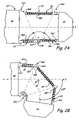
- FIG. 2A shows a three bearing swivel duct of FIG. 1 configured for conventional operation.
- FIG. 2B shows the three bearing swivel duct of FIG. 2A configured for vertical landing or take-off operation.
- FIG. 3 shows a cut-away portion of the three bearing swivel duct of FIGS. 2A and 2B .
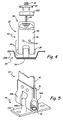
- FIG. 4 shows a partially exploded, partially broken view of the exhaust liner suspension system of the present invention.
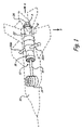
- FIG. 5 shows a coil pin of the present invention connecting a hanger and a bracket of an exhaust duct liner suspension system.
- FIG. 6 shows a front view of the coil pin of the present invention inserted in a bracket of an exhaust duct liner suspension system.
- FIG. 7 shows the winding of the coil pin of the present invention.
- FIG. 1 shows jet-powered aircraft 10 having short take-off vertical landing (STOVL) gas turbine engine 12 .
- Engine 12 includes multiple thrust producing and thrust directing elements which enable aircraft 10 to take-off on a shortened runway and land vertically.
- Engine 12 includes lift fan 14 , lift fan shaft 16 , power plant 18 , control ducts 20 A and 20 B, three bearing swivel duct 22 and exhaust nozzle 24 .
- Power plant 18 is the primary thrust-producing element of engine 12 and is used to produce thrust oriented in the x direction.
- Three bearing swivel duct (3BSD) 22 directs the thrust of power plant 18 in the x direction when in configuration A (as shown by 3BSD 22 in solid lines).
- 3BSD 22 is adjustable to redirect the thrust of power plant 18 in the y direction when in configuration B (as shown by 3BSD 22 in dashed lines). 3BSD 22 is also be used to produce thrust in intermediate directions. Nozzle 24 increases and focuses the thrust produced by power plant 18 and is secured to the tail end of 3BSD 22 .
- 3BSD 22 is used in configuration A during traditional take off and flight operations of aircraft 10 in the x direction.
- 3BSD 22 is positioned in intermediate directions to facilitate short take-off operations.
- 3BSD 22 is positioned in configuration B to assist lift fan 14 in vertical landing operations. Lift fan 14 is selectively driven by power plant 18 through lift fan shaft 16 , and is used to produce thrust in they direction near the forward portion of aircraft 10 .
- control ducts 20 A and 20 B redirect a portion of the thrust produced by power plant 18 in the y direction underneath the wings, at a location away from the axis on which power plant 18 and lift fan 14 produce thrust in the y direction.
- Control ducts 20 A and 20 B are selectively engaged to balance the roll of aircraft 10 during vertical landing and take-off operations.
- FIG. 2A shows three bearing swivel duct (3BSD) 22 of FIG. 1 in configuration A with nozzle 24 oriented along the x axis.
- FIG. 2B shows 3BSD 22 in configuration B with nozzle 24 oriented 105° from the x axis.
- 3BSD 22 is positioned between power plant 18 and nozzle 24 of engine 12 .
- 3BSD 22 comprises front duct 26 A, intermediate duct 26 B, rear duct 26 C, front liner 28 A, intermediate liner 28 B, rear liner 28 C, a plurality of suspension systems 30 and swivel bearings 32 A- 32 C.
- Front duct 26 A is connected with power plant 18 along a vertical axis using forward swivel bearing 32 A.
- Swivel bearing 32 A allows front duct 26 A to rotate 360° with respect to power plant 18 .
- Swivel bearing 32 A is controlled by a central control system of aircraft 10 that positions front duct 26 A for each desired operational mode of aircraft 10 .
- intermediate duct 26 B is connected with front duct 26 A using intermediate swivel bearing 32 B.
- Swivel bearing 32 B is centrally controlled and allows intermediate duct 26 B to rotate 360° with respect to front duct 26 A.
- intermediate duct 26 B is angled at angle b and the aft edge of front duct 26 A is angled at angle a such that when they rotate with respect to each other, the position of nozzle 24 rotates about the x-axis.
- rear duct 26 C is connected with intermediate duct 26 B using aft swivel bearing 32 C. Swivel bearing 32 C is centrally controlled and allows rear duct 26 C to rotate 360° with respect to intermediate duct 26 B.
- the forward edge of rear duct 26 C is angled at angle c such that when it rotates, the position of nozzle 24 rotates about the x-axis.
- Angles a, b and c are selected such that in configuration A 3BSD is generally horizontal, but can pivot to reposition nozzle 24 .
- FIG. 2B shows front duct 26 A rotated 180° with respect to power plant 18 , intermediate duct 26 B rotated 180° with respect to front duct 26 A and rear duct 26 C rotated 180° with respect to intermediate duct 26 B.
- 3BSD 22 is angled downward a total of 105° with respect to the x axis in configuration B.
- Nozzle 22 can also be oriented 40° from the x axis by rotating only front duct 26 A and intermediate duct 26 B 180° each.
- exhaust liners 28 A- 28 C have smaller diameters than exhaust ducts 26 A- 26 C and cannot be mounted directly to the exhaust ducts. Therefore, front liner 28 A, intermediate liner 28 B and rear liner 28 C are suspended from front duct 26 A, intermediate duct 26 B and rear duct 26 C, respectively, using a plurality of suspension systems 30 .
- Suspension systems 30 span the difference in diameters of ducts 26 A- 26 C and liners 28 A- 28 C and can be tailored to for specific lengths. Typically there are about ten to fifteen rows of suspension systems per duct segment, with the bulk of them concentrated near the widest sections of each duct segment. To further facilitate assembly and disassembly, suspension systems 30 utilize a hinged hanger system.
- FIG. 3 shows a cut-away portion of intermediate duct 26 B and intermediate duct liner 28 B connected by suspension systems 30 of FIGS. 2A and 2B .
- Suspension systems 30 include cold sheet bracket 34 , hinge 36 , coil pin 38 , duct bracket, or hanger, 40 , flange washer 42 , T-bolt 44 , lock nut 46 and axial stiffener 48 .
- Suspension systems 30 connect intermediate duct 26 B with intermediate liner 28 B.
- Cold sheet bracket 34 is connected with intermediate duct liner 28 B at corrugation 50 .
- Cold sheet bracket 34 is inserted through hole 51 in duct liner 28 B from underneath duct liner 28 B.
- Hinge 36 forms a rotatable connection with bracket 34 utilizing coil pin 38 .
- Coil pin 38 comprises a thin metal sheet wound about a central axis to form a spiral.
- Coil pin 38 is compression fit into a bore in cold sheet bracket 34 such that coil pin will not rotate with respect to cold sheet bracket 34 .
- each cold sheet bracket, hinge and coil pin are pre-assembled as a hinge assembly before the cold sheet bracket is assembled with exhaust liner 28 B.
- Hinge 36 receives duct bracket 40 , which connect with intermediate duct 26 B.
- Hinges 36 are joined with each other through axial stiffener 48 , which also provides axial load sharing amongst brackets 40 .
- Bracket 40 , hinge 36 and axial stiffener 48 are fastened together with, for example threaded fasteners or rivets.
- T-bolt 44 is inserted through intermediate duct 26 B into duct bracket 40 .
- Flange washer 42 is placed around T-bolt 44 and into intermediate duct 26 B and duct bracket 40 to restrain T-bolt 44 from rotating while torquing lock nut 46 which secures intermediate duct 26 B between bracket 40 and flange washer 42 .
- Flange washer 42 provides for proper orientation of T-bolt 44 and load distribution functions.
- bracket 40 is rotatable about coil pin 38 . Brackets 40 rotate in unison using stiffener 48 and rotate downward into corrugations 50 as indicated by arrow R.
- suspension system 30 are insertable past swivel bearing joints 32 A- 32 C during assembly of 3BSD 22 . Since brackets 40 are designed to rotate, there is, inherently, some play in each suspension system 30 . Coil pin 38 of the present invention reduces the amount of vibration produced by interaction of bracket 34 , hinge 36 and bracket 40 .
- FIG. 4 shows a partially exploded, partially broken view of suspension system 30 including coil pin 38 of the present invention.
- Suspension system 30 is exemplary of the suspension system of the present invention.
- Bracket 40 or hanger 40 , is the primary member used for connecting exhaust liner 28 B with exhaust duct 26 B.
- bracket 40 is connected with exhaust duct 26 B with T-bolt 44 and locking nut 46 through holes in duct 26 B and the top of bracket 40 .
- hinge mechanism 56 connects bracket 40 with exhaust liner 28 B.
- Hinge mechanism 56 is comprised of hinge 36 , coil pin 38 and bracket 34 .
- Hinge mechanism. 56 is inserted through hole 51 from underneath exhaust liner 28 B with coil pin 38 perpendicular to the axis of exhaust liner 28 B and then rotated 90° to the orientation shown in FIG. 4 once inserted.
- Cold sheet bracket 34 is fastened to intermediate liner 28 B between corrugation 50 of duct 28 B so that bracket 40 can be folded down into corrugation 50 .
- Corrugation 50 provides a secondary retention system for coil pin 38 by preventing coil pin 38 from fully disengaging bracket 34 and hinge 36 should it fail to hold in place.
- Cold sheet bracket 34 is connected to intermediate liner 28 B with, for example, threaded fasteners or rivets.
- Coil pin 38 is forced fit with the bore in bracket 34 and is loose fit with the hinge pin sockets in hinge 36 .
- coil pin 38 is not rotatable with respect to bracket 34 , but hinge 36 is rotatable with respect to coil pin 38 .
- FIG. 5 shows the insertion of coil pin 38 into the bore of cold sheet bracket 34 and the pin sockets of hinge 36 .
- Cold sheet bracket 34 includes base member 34 A for connecting with exhaust liner 28 B, and pedestal member 34 B for providing a bore for coil pin 38 .
- Hinge 36 includes a U-shaped bracket for receiving duct bracket 40 , and bores 49 for fastening hinge 36 with bracket 40 using, for example, threaded fasteners or rivets.
- Hinge 36 includes two hinge pin sockets 58 A and 58 B for receiving coil pin 38 .
- Sockets 58 A and 58 B include oval shaped bores for loosely receiving coil pin 38 so that hinge 36 can rotate about coil pin 38 . The oval shaped bores also allow for vertical movement of hinge 36 .
- hinge 36 moves downward with respect to coil pin 38 thus enabling hinge 36 to rotate downward without interference from intermediate duct 26 B.
- T-bolt 44 pulls the bottom of hinge 36 into contact with coil pin 38 , putting bracket 40 into tension.
- Cold sheet bracket 34 includes a circular bore for tightly receiving coil pin 38 and preventing its rotation within cold sheet bracket 34 .
- Sockets 58 A and 58 B are axially aligned with the bore of cold sheet bracket 34 and coil pin 38 so that coil pin 38 can be simultaneously inserted into the bore of cold sheet bracket 34 and sockets 58 A and 58 B. Therefore, bracket 40 and hinge 36 rotate on coil pin 38 thereby allowing bracket 40 to fold down into corrugation 50 .
- FIG. 6 shows the positioning of coil pin 38 within the bore of cold sheet bracket pedestal 34 B.
- FIG. 7 shows the winding of coil pin 38 of the present invention.
- Coil pin 38 is press fit into bore 60 of cold sheet bracket 34 .
- Coil pin 38 is produced by rolling a sheet of metal to form a coil having a spiral shape.
- Coil pin 38 can be made of any suitable aircraft grade alloy, with 302 stainless steel and nickel alloys being preferred.
- coil pin 38 is produced from a metal sheet 0.875 inches ( ⁇ 2.223 cm) wide.
- coil pin 38 is wrapped around its center axis approximately 2.0 to approximately 2.25 times (or from about two complete wraps to about 45° past two complete wraps), as shown by angle B in FIG. 7 . This results in approximately 270° to approximately 315° of contact between coil pin 38 and bore 60 , as shown by arrow C in FIG. 6 .
- This is an improvement over traditional slotted pins that essentially provide only three points of contact along the bore they are inserted into.
- Coil pin 38 has diameter A, which is selected to be slightly larger than the diameter of bore 60 when not compressed. In one embodiment, coil pin 38 has a diameter of approximately 0.21875 inches ( ⁇ 0.556 cm). When coil pin 38 is pressed into bore 60 , it compresses slightly and pushes out against bore 60 , thus providing a damped interference fit connection between bracket 34 and coil pin 38 . The resilient properties of coil pin 38 reduce the need for tight tolerancing in producing bore 60 in bracket 34 , which contributes to cost savings in the production of suspension system 30 . Bore 60 of bracket 34 does not have to be produced to the precise diameter required for forming a forced fit with coil pin 28 .
- coil pin 38 also eliminates the need for having to produce a traditional solid machined pin having the precise diameter required for forming a force fit with bore 60 . This eliminates machining procedures in the production of suspension system 30 , which is particularly advantageous when working with the expensive nickel and titanium alloys used in the aerospace industry.
- Coil pin 38 also assists in the assembly of suspension system 30 by reducing variation in assembly. Since coil pin 38 is compressible, the variation from pin to pin in the force required to insert coil pin 38 is smaller than the variation for slotted pins. In one embodiment the insertion force variation for coil pin 38 is approximately +/ ⁇ 20%, as compared with +/ ⁇ 50% for a slotted pin. This facilitates streamlined manufacture of suspension system 30 .
- coil pin 38 and bracket 34 will expand resulting in the diameters of coil pin 38 and bore 60 growing larger.
- the material used to produce coil pin 38 is selected to have a higher coefficient of thermal expansion than that of the material used for bracket 34 .
- coil pin 38 will increase in diameter an amount greater than bore 60 increases thereby retaining the force fit between the two bodies.
- the coil winding characteristics of coil pin 38 also result in the diameter of coil pin 38 expanding a greater amount than that of a solid hinge pin. This further ensures that a tight fit is maintained between bore 60 and coil pin 38 .
- Coil pin 38 also has only one sharp point of contact with bore 60 , indicated with arrow D.
- Traditional slotted pins have two edges along the slot that produce sharp points of contact with bores they are inserted into. It is desirable to eliminate sharp contact points with bore 60 to reduce the potential for damaging and weakening the inside of bore 60 .
Priority Applications (5)
| Application Number | Priority Date | Filing Date | Title |
|---|---|---|---|
| US11/326,004 US7581399B2 (en) | 2006-01-05 | 2006-01-05 | Damped coil pin for attachment hanger hinge |
| US11/514,293 US7721522B2 (en) | 2006-01-05 | 2006-08-31 | Torque load transfer attachment hardware |
| EP07866981A EP1974140B1 (de) | 2006-01-05 | 2007-01-05 | Gedämpfter spulenbolzen für einen befestigungshänggelenk |
| PCT/US2007/000406 WO2008054436A2 (en) | 2006-01-05 | 2007-01-05 | Damped coil pin for attachment hanger hinge |
| US12/648,061 US8661835B2 (en) | 2006-01-05 | 2009-12-28 | Bushing for torque load transfer attachment hardware |
Applications Claiming Priority (1)
| Application Number | Priority Date | Filing Date | Title |
|---|---|---|---|
| US11/326,004 US7581399B2 (en) | 2006-01-05 | 2006-01-05 | Damped coil pin for attachment hanger hinge |
Related Child Applications (1)
| Application Number | Title | Priority Date | Filing Date |
|---|---|---|---|
| US11/514,293 Continuation-In-Part US7721522B2 (en) | 2006-01-05 | 2006-08-31 | Torque load transfer attachment hardware |
Publications (2)
| Publication Number | Publication Date |
|---|---|
| US20070151229A1 US20070151229A1 (en) | 2007-07-05 |
| US7581399B2 true US7581399B2 (en) | 2009-09-01 |
Family
ID=38222914
Family Applications (1)
| Application Number | Title | Priority Date | Filing Date |
|---|---|---|---|
| US11/326,004 Active 2027-09-12 US7581399B2 (en) | 2006-01-05 | 2006-01-05 | Damped coil pin for attachment hanger hinge |
Country Status (3)
| Country | Link |
|---|---|
| US (1) | US7581399B2 (de) |
| EP (1) | EP1974140B1 (de) |
| WO (1) | WO2008054436A2 (de) |
Cited By (21)
| Publication number | Priority date | Publication date | Assignee | Title |
|---|---|---|---|---|
| US20090145133A1 (en) * | 2007-12-05 | 2009-06-11 | Michael Joseph Murphy | Exhaust liner attachment arrangement |
| US20090230213A1 (en) * | 2008-03-11 | 2009-09-17 | Harris Andrew H | Metal injection molding attachment hanger system for a cooling liner within a gas turbine engine swivel exhaust duct |
| US20100115965A1 (en) * | 2006-01-05 | 2010-05-13 | United Technologies Corporation | Torque load transfer attachment hardware |
| US20110016879A1 (en) * | 2006-07-28 | 2011-01-27 | United Technologies Corporation | Low profile attachment hanger system for a cooling liner within a gas turbine engine swivel exhaust duct |
| US9157394B2 (en) | 2012-08-15 | 2015-10-13 | United Technologies Corporation | Adjustable cable for exhaust duct liner hanger |
| US9255548B2 (en) | 2012-09-11 | 2016-02-09 | United Technologies Corporation | Sliding U-joint hanger for gas turbine engine nozzle |
| US9309833B2 (en) | 2012-10-22 | 2016-04-12 | United Technologies Corporation | Leaf spring hanger for exhaust duct liner |
| US9309834B2 (en) | 2012-05-31 | 2016-04-12 | United Technologies Corporation | Liner hanger cable |
| US9316174B2 (en) | 2012-06-04 | 2016-04-19 | United Technologies Corporation | Liner hanger with spherical washers |
| US9382875B2 (en) | 2012-08-15 | 2016-07-05 | United Technologies Corporation | Spherical button washer for exhaust duct liner hanger |
| US9476524B2 (en) | 2012-08-15 | 2016-10-25 | United Technologies Corporation | Support system bumper for exhaust duct liner hanger |
| US9494109B2 (en) | 2012-08-15 | 2016-11-15 | United Technologies Corporation | Pivoting ball stop for exhaust duct liner hanger |
| US9963990B2 (en) | 2015-05-26 | 2018-05-08 | Rolls-Royce North American Technologies, Inc. | Ceramic matrix composite seal segment for a gas turbine engine |
| US9964042B2 (en) | 2013-10-29 | 2018-05-08 | United Technologies Corporation | Bracket doubler |
| US10054080B2 (en) | 2012-10-22 | 2018-08-21 | United Technologies Corporation | Coil spring hanger for exhaust duct liner |
| US10087770B2 (en) | 2015-05-26 | 2018-10-02 | Rolls-Royce Corporation | Shroud cartridge having a ceramic matrix composite seal segment |
| EP3401537A1 (de) | 2017-05-11 | 2018-11-14 | United Technologies Corporation | Kabelbefestigungselement für eine abgasauskleidung |
| US10221713B2 (en) | 2015-05-26 | 2019-03-05 | Rolls-Royce Corporation | Shroud cartridge having a ceramic matrix composite seal segment |
| US10370998B2 (en) | 2015-05-26 | 2019-08-06 | Rolls-Royce Corporation | Flexibly mounted ceramic matrix composite seal segments |
| US10370997B2 (en) | 2015-05-26 | 2019-08-06 | Rolls-Royce Corporation | Turbine shroud having ceramic matrix composite seal segment |
| US10480337B2 (en) | 2017-04-18 | 2019-11-19 | Rolls-Royce North American Technologies Inc. | Turbine shroud assembly with multi-piece seals |
Families Citing this family (25)
| Publication number | Priority date | Publication date | Assignee | Title |
|---|---|---|---|---|
| EP3106094B1 (de) | 2004-11-26 | 2021-09-08 | Hologic, Inc. | Integriertes multimodus-mammographie-/tomosynthese-röntgensystem |
| US7631481B2 (en) * | 2004-12-01 | 2009-12-15 | United Technologies Corporation | Cooled duct for gas turbine engine |
| JP5554927B2 (ja) | 2006-02-15 | 2014-07-23 | ホロジック, インコーポレイテッド | トモシンセシスシステムを使用した乳房バイオプシおよびニードル位置特定 |
| US7814753B2 (en) * | 2006-07-25 | 2010-10-19 | United Technologies Corporation | Low profile attachment hanger system for a cooling liner within a gas turbine engine swivel exhaust duct |
| CN106420066B (zh) | 2009-10-08 | 2020-08-25 | 霍罗吉克公司 | 将穿刺活检组件引导到目标位置的方法及x射线成像系统 |
| US20110232262A1 (en) * | 2010-03-29 | 2011-09-29 | Barry Jr Thomas M | Radial and axial compliant sliding seal incorporating spring capturing features for improved bearing plane sealing in an articulating nozzle |
| US9075903B2 (en) | 2010-11-26 | 2015-07-07 | Hologic, Inc. | User interface for medical image review workstation |
| EP2684157B1 (de) | 2011-03-08 | 2017-12-13 | Hologic Inc. | System und verfahren für dualenergie- und/oder kontrastverstärkte brustbildgebung zur untersuchung, diagnose und biopsie |
| JP2014534042A (ja) | 2011-11-27 | 2014-12-18 | ホロジック, インコーポレイテッドHologic, Inc. | マンモグラフィーおよび/またはトモシンセシス画像データを使用して2d画像を生成するためのシステムおよび方法 |
| CN104135935A (zh) | 2012-02-13 | 2014-11-05 | 霍罗吉克公司 | 用于利用合成图像数据导航层析堆的系统和方法 |
| US9316315B2 (en) | 2012-03-09 | 2016-04-19 | United Technologies Corporation | Seal assembly |
| US10077681B2 (en) * | 2013-02-14 | 2018-09-18 | United Technologies Corporation | Compliant heat shield liner hanger assembly for gas turbine engines |
| US20140223919A1 (en) * | 2013-02-14 | 2014-08-14 | United Technologies Corporation | Flexible liner hanger |
| EP3366217B1 (de) | 2013-03-15 | 2019-12-25 | Hologic, Inc. | Tomosynthesegesteuerte biopsie in bauchlage |
| JP2016533803A (ja) | 2013-10-24 | 2016-11-04 | アンドリュー ピー. スミス, | X線誘導胸部生検をナビゲートするためのシステムおよび方法 |
| ES2943561T3 (es) | 2014-02-28 | 2023-06-14 | Hologic Inc | Sistema y método para generar y visualizar bloques de imagen de tomosíntesis |
| EP3181455B1 (de) * | 2015-12-16 | 2019-04-17 | AIRBUS HELICOPTERS DEUTSCHLAND GmbH | Flugzeug mit heisser abluft mit zwei schwenkbar gelagerten abgasabschnitten |
| JP7174710B2 (ja) | 2017-03-30 | 2022-11-17 | ホロジック, インコーポレイテッド | 合成乳房組織画像を生成するための標的オブジェクト増強のためのシステムおよび方法 |
| US11399790B2 (en) | 2017-03-30 | 2022-08-02 | Hologic, Inc. | System and method for hierarchical multi-level feature image synthesis and representation |
| US11455754B2 (en) | 2017-03-30 | 2022-09-27 | Hologic, Inc. | System and method for synthesizing low-dimensional image data from high-dimensional image data using an object grid enhancement |
| US11403483B2 (en) | 2017-06-20 | 2022-08-02 | Hologic, Inc. | Dynamic self-learning medical image method and system |
| US11883206B2 (en) | 2019-07-29 | 2024-01-30 | Hologic, Inc. | Personalized breast imaging system |
| WO2021062284A1 (en) | 2019-09-27 | 2021-04-01 | Hologic, Inc. | Ai system for predicting reading time and reading complexity for reviewing 2d/3d breast images |
| US11481038B2 (en) | 2020-03-27 | 2022-10-25 | Hologic, Inc. | Gesture recognition in controlling medical hardware or software |
| CN114562379B (zh) * | 2022-01-13 | 2023-05-05 | 中国航发沈阳发动机研究所 | 一种作动筒长距可调引气喷管 |
Citations (5)
| Publication number | Priority date | Publication date | Assignee | Title |
|---|---|---|---|---|
| US3557402A (en) * | 1968-12-04 | 1971-01-26 | Cem Co Inc | Coiled fastening pin |
| US3826088A (en) * | 1973-02-01 | 1974-07-30 | Gen Electric | Gas turbine engine augmenter cooling liner stabilizers and supports |
| US4438626A (en) | 1981-09-11 | 1984-03-27 | General Electric Company | Apparatus for attaching a ceramic member to a metal structure |
| US4465252A (en) * | 1983-04-08 | 1984-08-14 | Nickson Industries, Inc. | Compact universal hanger for tailpipes and the like |
| US4747543A (en) | 1987-04-14 | 1988-05-31 | United Technologies Corporation | Nozzle flap cooling liner |
-
2006
- 2006-01-05 US US11/326,004 patent/US7581399B2/en active Active
-
2007
- 2007-01-05 WO PCT/US2007/000406 patent/WO2008054436A2/en active Application Filing
- 2007-01-05 EP EP07866981A patent/EP1974140B1/de active Active
Patent Citations (5)
| Publication number | Priority date | Publication date | Assignee | Title |
|---|---|---|---|---|
| US3557402A (en) * | 1968-12-04 | 1971-01-26 | Cem Co Inc | Coiled fastening pin |
| US3826088A (en) * | 1973-02-01 | 1974-07-30 | Gen Electric | Gas turbine engine augmenter cooling liner stabilizers and supports |
| US4438626A (en) | 1981-09-11 | 1984-03-27 | General Electric Company | Apparatus for attaching a ceramic member to a metal structure |
| US4465252A (en) * | 1983-04-08 | 1984-08-14 | Nickson Industries, Inc. | Compact universal hanger for tailpipes and the like |
| US4747543A (en) | 1987-04-14 | 1988-05-31 | United Technologies Corporation | Nozzle flap cooling liner |
Cited By (30)
| Publication number | Priority date | Publication date | Assignee | Title |
|---|---|---|---|---|
| US20100115965A1 (en) * | 2006-01-05 | 2010-05-13 | United Technologies Corporation | Torque load transfer attachment hardware |
| US8661835B2 (en) * | 2006-01-05 | 2014-03-04 | United Technologies Corporation | Bushing for torque load transfer attachment hardware |
| US20110016879A1 (en) * | 2006-07-28 | 2011-01-27 | United Technologies Corporation | Low profile attachment hanger system for a cooling liner within a gas turbine engine swivel exhaust duct |
| US7975488B2 (en) * | 2006-07-28 | 2011-07-12 | United Technologies Corporation | Low profile attachment hanger system for a cooling liner within a gas turbine engine swivel exhaust duct |
| US7866158B2 (en) * | 2007-12-05 | 2011-01-11 | United Technologies Corporation | Exhaust liner attachment arrangement |
| US20090145133A1 (en) * | 2007-12-05 | 2009-06-11 | Michael Joseph Murphy | Exhaust liner attachment arrangement |
| US20090230213A1 (en) * | 2008-03-11 | 2009-09-17 | Harris Andrew H | Metal injection molding attachment hanger system for a cooling liner within a gas turbine engine swivel exhaust duct |
| US9297335B2 (en) * | 2008-03-11 | 2016-03-29 | United Technologies Corporation | Metal injection molding attachment hanger system for a cooling liner within a gas turbine engine swivel exhaust duct |
| US9309834B2 (en) | 2012-05-31 | 2016-04-12 | United Technologies Corporation | Liner hanger cable |
| US9316174B2 (en) | 2012-06-04 | 2016-04-19 | United Technologies Corporation | Liner hanger with spherical washers |
| US9476524B2 (en) | 2012-08-15 | 2016-10-25 | United Technologies Corporation | Support system bumper for exhaust duct liner hanger |
| US9382875B2 (en) | 2012-08-15 | 2016-07-05 | United Technologies Corporation | Spherical button washer for exhaust duct liner hanger |
| US9157394B2 (en) | 2012-08-15 | 2015-10-13 | United Technologies Corporation | Adjustable cable for exhaust duct liner hanger |
| US9494109B2 (en) | 2012-08-15 | 2016-11-15 | United Technologies Corporation | Pivoting ball stop for exhaust duct liner hanger |
| US10180105B2 (en) | 2012-08-15 | 2019-01-15 | United Technologies Corporation | Adjustable cable for exhaust duct liner hanger |
| US9255548B2 (en) | 2012-09-11 | 2016-02-09 | United Technologies Corporation | Sliding U-joint hanger for gas turbine engine nozzle |
| US10125723B1 (en) | 2012-10-22 | 2018-11-13 | United Technologies Corporation | Coil spring hanger for exhaust duct liner |
| US10054080B2 (en) | 2012-10-22 | 2018-08-21 | United Technologies Corporation | Coil spring hanger for exhaust duct liner |
| US9309833B2 (en) | 2012-10-22 | 2016-04-12 | United Technologies Corporation | Leaf spring hanger for exhaust duct liner |
| US9964042B2 (en) | 2013-10-29 | 2018-05-08 | United Technologies Corporation | Bracket doubler |
| US10087770B2 (en) | 2015-05-26 | 2018-10-02 | Rolls-Royce Corporation | Shroud cartridge having a ceramic matrix composite seal segment |
| US9963990B2 (en) | 2015-05-26 | 2018-05-08 | Rolls-Royce North American Technologies, Inc. | Ceramic matrix composite seal segment for a gas turbine engine |
| US10221713B2 (en) | 2015-05-26 | 2019-03-05 | Rolls-Royce Corporation | Shroud cartridge having a ceramic matrix composite seal segment |
| US10370998B2 (en) | 2015-05-26 | 2019-08-06 | Rolls-Royce Corporation | Flexibly mounted ceramic matrix composite seal segments |
| US10370997B2 (en) | 2015-05-26 | 2019-08-06 | Rolls-Royce Corporation | Turbine shroud having ceramic matrix composite seal segment |
| US10907493B2 (en) | 2015-05-26 | 2021-02-02 | Rolls-Royce Corporation | Turbine shroud having ceramic matrix composite seal segment |
| US11008881B2 (en) | 2015-05-26 | 2021-05-18 | Rolls-Royce Corporation | Shroud cartridge having a ceramic matrix composite seal segment |
| US10480337B2 (en) | 2017-04-18 | 2019-11-19 | Rolls-Royce North American Technologies Inc. | Turbine shroud assembly with multi-piece seals |
| EP3401537A1 (de) | 2017-05-11 | 2018-11-14 | United Technologies Corporation | Kabelbefestigungselement für eine abgasauskleidung |
| US10533457B2 (en) | 2017-05-11 | 2020-01-14 | United Technologies Corporation | Exhaust liner cable fastener |
Also Published As
| Publication number | Publication date |
|---|---|
| WO2008054436A2 (en) | 2008-05-08 |
| EP1974140B1 (de) | 2013-03-27 |
| EP1974140A2 (de) | 2008-10-01 |
| WO2008054436A3 (en) | 2009-04-09 |
| US20070151229A1 (en) | 2007-07-05 |
| EP1974140A4 (de) | 2011-04-06 |
Similar Documents
| Publication | Publication Date | Title |
|---|---|---|
| US7581399B2 (en) | Damped coil pin for attachment hanger hinge | |
| US7721522B2 (en) | Torque load transfer attachment hardware | |
| US10808622B2 (en) | Turbine engine case mount and dismount | |
| EP2080879B1 (de) | System zur Montage einer Gasturbine | |
| US5088279A (en) | Duct support assembly | |
| US7814753B2 (en) | Low profile attachment hanger system for a cooling liner within a gas turbine engine swivel exhaust duct | |
| EP3273010B1 (de) | Mittelturbinenrahmen | |
| US5746391A (en) | Mounting for coupling a turbofan gas turbine engine to an aircraft structure | |
| US8684303B2 (en) | Gas turbine engine compressor arrangement | |
| US5921500A (en) | Integrated failsafe engine mount | |
| US7975488B2 (en) | Low profile attachment hanger system for a cooling liner within a gas turbine engine swivel exhaust duct | |
| US8733693B2 (en) | Aircraft engine assembly comprising an annular load-transfer structure surrounding the central casing of a turbojet engine | |
| US20130233997A1 (en) | Turbine engine case mount | |
| US11149559B2 (en) | Turbine section assembly with ceramic matrix composite vane | |
| US20200182153A1 (en) | Turbine engine case attachment and a method of using the same | |
| EP3549856B1 (de) | Lüfterhaubenverriegelungskonzept für ein rumpfmontiertes triebwerk | |
| US20130255276A1 (en) | Transition Duct Mounting System | |
| EP3730772B1 (de) | Triebwerksgondelsystem mit einer befestigungsstruktur umfassend eine gesickte befestigungsklammer | |
| US20130042629A1 (en) | Turbomachine load management assembly | |
| US10578015B2 (en) | Flexible joints assembly with flexure rods |
Legal Events
| Date | Code | Title | Description |
|---|---|---|---|
| AS | Assignment |
Owner name: UNITED TECHNOLOGIES CORPORATION, CONNECTICUT Free format text: ASSIGNMENT OF ASSIGNORS INTEREST;ASSIGNORS:FARAH, JORGE I.;NACKOUL, MICHAEL E.;CINTRON, JOSE M.;REEL/FRAME:017442/0595;SIGNING DATES FROM 20051221 TO 20051228 |
|
| AS | Assignment |
Owner name: NAVY, DEPT OF THE, MARYLAND Free format text: CONFIRMATORY LICENSE;ASSIGNOR:UNITED TECHNOLOGIES;REEL/FRAME:017648/0495 Effective date: 20060118 |
|
| STCF | Information on status: patent grant |
Free format text: PATENTED CASE |
|
| FPAY | Fee payment |
Year of fee payment: 4 |
|
| FPAY | Fee payment |
Year of fee payment: 8 |
|
| AS | Assignment |
Owner name: RAYTHEON TECHNOLOGIES CORPORATION, MASSACHUSETTS Free format text: CHANGE OF NAME;ASSIGNOR:UNITED TECHNOLOGIES CORPORATION;REEL/FRAME:054062/0001 Effective date: 20200403 |
|
| MAFP | Maintenance fee payment |
Free format text: PAYMENT OF MAINTENANCE FEE, 12TH YEAR, LARGE ENTITY (ORIGINAL EVENT CODE: M1553); ENTITY STATUS OF PATENT OWNER: LARGE ENTITY Year of fee payment: 12 |
|
| AS | Assignment |
Owner name: RAYTHEON TECHNOLOGIES CORPORATION, CONNECTICUT Free format text: CORRECTIVE ASSIGNMENT TO CORRECT THE AND REMOVE PATENT APPLICATION NUMBER 11886281 AND ADD PATENT APPLICATION NUMBER 14846874. TO CORRECT THE RECEIVING PARTY ADDRESS PREVIOUSLY RECORDED AT REEL: 054062 FRAME: 0001. ASSIGNOR(S) HEREBY CONFIRMS THE CHANGE OF ADDRESS;ASSIGNOR:UNITED TECHNOLOGIES CORPORATION;REEL/FRAME:055659/0001 Effective date: 20200403 |
|
| AS | Assignment |
Owner name: RTX CORPORATION, CONNECTICUT Free format text: CHANGE OF NAME;ASSIGNOR:RAYTHEON TECHNOLOGIES CORPORATION;REEL/FRAME:064714/0001 Effective date: 20230714 |