US7565389B2 - Method for determining filter coefficients of a digital filter and digital filter - Google Patents
Method for determining filter coefficients of a digital filter and digital filter Download PDFInfo
- Publication number
- US7565389B2 US7565389B2 US10/532,903 US53290305A US7565389B2 US 7565389 B2 US7565389 B2 US 7565389B2 US 53290305 A US53290305 A US 53290305A US 7565389 B2 US7565389 B2 US 7565389B2
- Authority
- US
- United States
- Prior art keywords
- input
- filter
- filter coefficients
- multiplying
- scaled
- Prior art date
- Legal status (The legal status is an assumption and is not a legal conclusion. Google has not performed a legal analysis and makes no representation as to the accuracy of the status listed.)
- Expired - Fee Related, expires
Links
Images


Classifications
-
- H—ELECTRICITY
- H03—ELECTRONIC CIRCUITRY
- H03H—IMPEDANCE NETWORKS, e.g. RESONANT CIRCUITS; RESONATORS
- H03H17/00—Networks using digital techniques
- H03H17/02—Frequency selective networks
- H03H17/0223—Computation saving measures; Accelerating measures
- H03H17/0225—Measures concerning the multipliers
Definitions
- the invention relates to a method for modifying filter coefficients for a digital filter, more particularly for UMTS (Universal Mobile Telecommunication System), in which the filter coefficients are predetermined and modified in a filter design program. Furthermore, the invention relates to a digital filter of this type.
- UMTS Universal Mobile Telecommunication System
- Digital filters are used, for example, as pulse shaping filters and matched filters in the UMTS standard (3GPP, TS 25.201: UE Radio Transmission and Reception (FDD), V3.2.0) and (3GPP, TS 25.213: Spreading and Modulation (FDD), V3.0.0).
- FDD Radio Transmission and Reception
- TS 25.213 Spreading and Modulation
- a hardware implementation necessary as a result and having its own components (chips) for the filters leads to much surface area in the appliance and to increased energy consumption.
- the ideal filter coefficients previously determined in a filter design program are quantized and scaled so that they can be processed by a simple adding operation and costly multipliers are avoided.
- the filter coefficients simplified by quantization and scaling are not determined in the respective appliance that comprises the filter function. They are determined from the ideal filter coefficients in an extended filter design program and subsequently implemented in the appliance.
- the quantized and scaled filter coefficients simplify the numerical complexity of the computation of the filtered signal. This allows to realize the filter function that has a small required area or space in the appliance and with little energy consumption.
- the filter may be an up-link and/or down-link, root-raised cosine filter of the UMTS with fixed-point arithmetic.
- the described measures may also be used in other non-recursive filters working with fixed-point arithmetic.
- FIG. 1 shows a FIR filter according to the state of the art
- FIG. 2 shows an improved filter arrangement with adder stages for the filter coefficients
- FIG. 3 shows one of the adder stages with three adders
- FIG. 4 alternatively shows an adder stage with one adder
- FIG. 5 alternatively shows an adder stage with selectable filter coefficients
- FIG. 6 shows a flow chart of the determination of the filter coefficients
- FIG. 7 shows a computation scheme for the multiplication by filter coefficients according to the state of the art
- FIG. 8 shows a computation scheme for the multiplication by a quantized filter coefficient
- FIG. 9 shows the quantity response for the evaluation of 4 “1” bits per coefficient
- FIG. 10 shows the quantity response for an evaluation of 3 “1” bits per coefficient
- FIG. 11 shows the quantity response for the evaluation of 2 “1” bits per coefficient
- FIG. 12 shows the quantization error in scaling factors between 1.5 and 2.3
- FIG. 13 shows a multiplier for the multiplication by squares.
- FIG. 1 In prior-art filters ( FIG. 1 ) an input signal X is multiplied by filter coefficients b N ⁇ 1 to b 0 in a plurality of multipliers 1 .
- the filter coefficients are predetermined by means of a filter design program corresponding to the desired type of filter.
- the resulting partial signals Y N ⁇ 1 to Y 0 are summed by adders 2 in a time-delayed manner (z ⁇ 1 ), the sum denoting the filtered output signal V.
- the ideal frequency response is shown in a dashed line in the FIGS. 9 to 12 for a Root-Raised Cosine Filter.
- the flow chart of FIG. 6 diagrammatically shows how new filter coefficients ⁇ v are formed from the predetermined filter coefficients b v . This is effected prior to the implementation of the filter coefficients in the filter.
- n of the “1” bits found after the most significant bit (MSB) is limited to a certain maximum number n, where n is 4, 3 or 2 in the examples described.
- the number n may be different for each adder stage depending on the coefficients provided. This is based on the recognition that a multiplication of a signal value by a filter coefficient having few “1” bits needs fewer adding operations than a multiplication by an arbitrary filter coefficient of a same effective word length.
- step 1 the binary value is limited to four “1” bits after the most significant bit, here 0. This corresponds to a decimal value of 0.703125, which as against the decimal original value means a quantization error of 0.013671875.
- a second step the next bit following the last “1” bit of step 1 is considered, which again is a “1” bit in the example. Since this bit is a “1” bit, a rounding is made in the next step, so that the binary value 0.1011110 arises. This corresponds to a decimal value 0.71875 which, compared to the decimal original value—irrespective of the scaling factor used—means a quantization error of ⁇ 0.00195125. The rounding thus considerably reduces the quantization error.
- FIG. 8 represents in comparison to FIG. 7 the computation scheme in which “217” is processed with said quantized and scaled filter factor in a decimal way: 0.71875 or binary way 0.101110, respectively.
- the filter factor can be unambiguously described by the (maximum n) positions of all bits set to “1”, in this case by the positions i 0 , k 0 , l 0 and m 0 having the values 1, 3, 4 and 5.
- This processing requires only four steps i 0 , k 0 , l 0 , m 0 .
- Each multiplication by this “1” corresponds to a shift of the input signal, here decimal: 217, binary 11011001.
- i 0 is a shift by one position
- k 0 is a shift by three positions
- l 0 a shift by four positions
- m 0 a shift by five positions.
- Such shifts can be realized with little circuitry because only data lines need to be properly connected for this purpose, as is shown by FIG. 13 via a shift by one position.
- the optimum scaling factor s 0 can be sought in a limited interval, for example, in the interval from 1 to 2 or in the interval from 1 ⁇ 2 ⁇ 2 to ⁇ 2.
- Said filter coefficients ⁇ v allow a simplified filter structure or a simplified implementation of the filter, respectively, because multipliers are replaced by adders.
- FIG. 2 schematically shows the structure of the filter.
- the multipliers 1 of FIG. 1 are replaced by adder stages ADD 3 in which the scaled and quantized filter coefficients ⁇ v , ⁇ N ⁇ 1 to ⁇ 0 respectively, are processed.
- a final stage 4 which may be arranged as a multiplier, a sum signal is processed with a factor s 0 reciprocal to the scaling factor of the filter coefficient 1/s 0 , to do away with the effect the scaling factor has on the output signal V.
- the final stage 4 may be omitted if the absolute value does not play a decisive role.
- FIG. 3 shows one of the adder stages ADD 3 for the filter coefficient b N ⁇ 1 .
- four multipliers 5 , 6 , 7 , 8 are provided which are designed for the multiplication by squares, that is, ⁇ i N ⁇ 1 , ⁇ k N ⁇ 1 , ⁇ l N ⁇ 1 , ⁇ m N ⁇ 1 in accordance with the respective filter coefficient, while these powers correspond to the example i 0 , k 0 , l 0 , m 0 of FIG. 8 .
- the result of the multipliers 5 and 6 is summed in an adder 9 .
- the result of the multipliers 7 and 8 is summed in an adder 11 .
- the results of the two adders are added in a further adder 10 to an intermediate signal Y N ⁇ 1 .
- the range of values of the inputs i, k, l and m is situated between 0 and M ⁇ 1 and connects one of the respective inputs X 0 . . . X M ⁇ 1 with one of the outputs.
- the output X i is determined by i
- x m is determined by m and so on.
- M in this example is 8 (compare FIG. 7 , FIG. 8 ).
- FIG. 13 shows one of the squaring multipliers 5 , 6 , 7 , 8 .
- This multiplier is formed by a simple connection of the data lines between the 8-bit input and the 8-bit output.
- FIG. 13 shows the connection for the case of the shift by one position. In the other cases mentioned a respective other connection is selected.
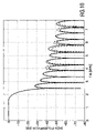
- FIG. 12 shows the curve of the quantization error E(s) described above with scaling factors in the range from 1.6 to 2.1.
- the quantization error shows a minimum at about 1.97. This value is accordingly used as the scaling factor s 0 .
- the quantization and optimization of the scaling factor has achieved that instead of costly multipliers ( FIG. 1 ), simple adder stages 3 can be used which reduces the required chip area of the hardware.
- the multipliers 5 to 8 of the adder stage 3 can be manufactured in a considerably simpler fashion, contrary to the multipliers of FIG. 1 . Since fewer arithmetic operations are necessary than in the state of the art, also the power consumption is reduced. The distortions of the signal are slight and depend on the selection of the number n.
- the processing rate is increased if the additions in all adder stages 3 are carried out simultaneously and by equally many adders.
Landscapes
- Engineering & Computer Science (AREA)
- Computing Systems (AREA)
- Theoretical Computer Science (AREA)
- Physics & Mathematics (AREA)
- Computer Hardware Design (AREA)
- Mathematical Physics (AREA)
- Compression, Expansion, Code Conversion, And Decoders (AREA)
Abstract
Description
E(s)=Σ|b v −sx β v|2
is determined (compare
βv =Q(b v /s 0)
Q then describes the quantization.
| Stage | Binary | Decimal | quantization error |
| original value | 0.101101111 | 0.716796875 | — |
| step 1:4 “1” bits | 0.101101 | 0.703125 | 0.013671875 |
| consider next bit | 0.1011011 | 0.7109375 | 0.005859375 |
| round at fourth “1” bit | 0.101110 | 0.71875 | 0.00195125 |
Claims (19)
Applications Claiming Priority (3)
| Application Number | Priority Date | Filing Date | Title |
|---|---|---|---|
| DE10250555A DE10250555A1 (en) | 2002-10-30 | 2002-10-30 | Method for determining filter coefficients of a digital filter and digital filter |
| DE10250555.1 | 2002-10-30 | ||
| PCT/IB2003/004685 WO2004040757A1 (en) | 2002-10-30 | 2003-10-20 | Method for determining filter coefficients of a digital filter and digital filter |
Publications (2)
| Publication Number | Publication Date |
|---|---|
| US20050289201A1 US20050289201A1 (en) | 2005-12-29 |
| US7565389B2 true US7565389B2 (en) | 2009-07-21 |
Family
ID=32114964
Family Applications (1)
| Application Number | Title | Priority Date | Filing Date |
|---|---|---|---|
| US10/532,903 Expired - Fee Related US7565389B2 (en) | 2002-10-30 | 2003-10-20 | Method for determining filter coefficients of a digital filter and digital filter |
Country Status (7)
| Country | Link |
|---|---|
| US (1) | US7565389B2 (en) |
| EP (1) | EP1559193A1 (en) |
| JP (1) | JP4665099B2 (en) |
| CN (1) | CN100525102C (en) |
| AU (1) | AU2003269403A1 (en) |
| DE (1) | DE10250555A1 (en) |
| WO (1) | WO2004040757A1 (en) |
Cited By (5)
| Publication number | Priority date | Publication date | Assignee | Title |
|---|---|---|---|---|
| US20080016136A1 (en) * | 2006-07-13 | 2008-01-17 | Sanyo Electric Co., Ltd. | Filtering Integrated Circuit |
| US20080200199A1 (en) * | 2003-05-09 | 2008-08-21 | Philips Intellectual Property & Standards Gmbh | Method and Arrangement For Setting the Transmission of a Mobile Communication Device |
| US10410700B1 (en) | 2018-09-28 | 2019-09-10 | The Mitre Corporation | Systems and method for a low-power correlator architecture using shifting coefficients |
| US10879877B1 (en) | 2018-09-28 | 2020-12-29 | The Mitre Corporation | Systems and method for a low power correlator architecture using distributed arithmetic |
| US20220085799A1 (en) * | 2020-09-17 | 2022-03-17 | xMEMS Labs, Inc. | Filter and Method with Multiplication Operation Approximation Capability |
Families Citing this family (6)
| Publication number | Priority date | Publication date | Assignee | Title |
|---|---|---|---|---|
| US8098722B2 (en) * | 2005-03-29 | 2012-01-17 | Qualcomm Incorporated | Method and apparatus for equalization control |
| CN104820151B (en) * | 2015-05-08 | 2017-11-14 | 天津百利机械装备集团有限公司中央研究院 | A kind of signal calibrating method of 100A total digitalizations Active Power Filter-APF |
| CN110365314B (en) * | 2019-06-04 | 2020-04-07 | 杭州电子科技大学 | Design method of separable two-dimensional FIR filter with sparse coefficient |
| CN110365310B (en) * | 2019-06-26 | 2020-03-03 | 杭州电子科技大学 | A Coefficient Quantization Method for Separable Two-dimensional FIR Filters |
| US11223891B2 (en) * | 2020-02-19 | 2022-01-11 | xMEMS Labs, Inc. | System and method thereof |
| WO2023223385A1 (en) * | 2022-05-16 | 2023-11-23 | 日本電信電話株式会社 | Signal processing device and signal processing method |
Citations (7)
| Publication number | Priority date | Publication date | Assignee | Title |
|---|---|---|---|---|
| US4791597A (en) | 1986-10-27 | 1988-12-13 | North American Philips Corporation | Multiplierless FIR digital filter with two to the Nth power coefficients |
| US5548540A (en) * | 1994-06-24 | 1996-08-20 | General Electric Company | Decimation filter having a selectable decimation ratio |
| EP0766388A2 (en) | 1995-09-30 | 1997-04-02 | Samsung Electronics Co., Ltd. | Method for processing signal in CSD filter and circuit suitable for the method |
| US5732004A (en) | 1995-11-14 | 1998-03-24 | Advanced Micro Devices, Inc. | DSP architecture for a FIR-type filter and method |
| WO2001022582A1 (en) | 1999-09-20 | 2001-03-29 | Koninklijke Philips Electronics Nv | Fir filter utilizing programmable shifter |
| US6243729B1 (en) * | 1998-12-31 | 2001-06-05 | Texas Instruments Incorporated | Digital finite-impulse-response (FIR) filter with a modified architecture based on high order Radix-N numbering |
| US6311203B1 (en) | 1998-07-27 | 2001-10-30 | Mitsubishi Denki Kabushiki Kaisha | Multiplier, and fixed coefficient FIR digital filter having plural multipliers |
Family Cites Families (1)
| Publication number | Priority date | Publication date | Assignee | Title |
|---|---|---|---|---|
| US5784419A (en) * | 1996-10-04 | 1998-07-21 | Motorola, Inc. | Efficient digital filter and method using coefficient precombing |
-
2002
- 2002-10-30 DE DE10250555A patent/DE10250555A1/en not_active Withdrawn
-
2003
- 2003-10-20 AU AU2003269403A patent/AU2003269403A1/en not_active Abandoned
- 2003-10-20 CN CNB200380102542XA patent/CN100525102C/en not_active Expired - Fee Related
- 2003-10-20 JP JP2004547892A patent/JP4665099B2/en not_active Expired - Fee Related
- 2003-10-20 US US10/532,903 patent/US7565389B2/en not_active Expired - Fee Related
- 2003-10-20 WO PCT/IB2003/004685 patent/WO2004040757A1/en not_active Ceased
- 2003-10-20 EP EP03751185A patent/EP1559193A1/en not_active Ceased
Patent Citations (10)
| Publication number | Priority date | Publication date | Assignee | Title |
|---|---|---|---|---|
| US4791597A (en) | 1986-10-27 | 1988-12-13 | North American Philips Corporation | Multiplierless FIR digital filter with two to the Nth power coefficients |
| US5548540A (en) * | 1994-06-24 | 1996-08-20 | General Electric Company | Decimation filter having a selectable decimation ratio |
| EP0766388A2 (en) | 1995-09-30 | 1997-04-02 | Samsung Electronics Co., Ltd. | Method for processing signal in CSD filter and circuit suitable for the method |
| US5831880A (en) * | 1995-09-30 | 1998-11-03 | Samsung Electronics Co., Ltd. | Method for processing a signal in a CSD filter and a circuit therefor |
| EP0766388B1 (en) | 1995-09-30 | 2005-12-07 | Samsung Electronics Co., Ltd. | Method for processing signal in CSD filter and circuit suitable for the method |
| US5732004A (en) | 1995-11-14 | 1998-03-24 | Advanced Micro Devices, Inc. | DSP architecture for a FIR-type filter and method |
| US6311203B1 (en) | 1998-07-27 | 2001-10-30 | Mitsubishi Denki Kabushiki Kaisha | Multiplier, and fixed coefficient FIR digital filter having plural multipliers |
| US6243729B1 (en) * | 1998-12-31 | 2001-06-05 | Texas Instruments Incorporated | Digital finite-impulse-response (FIR) filter with a modified architecture based on high order Radix-N numbering |
| WO2001022582A1 (en) | 1999-09-20 | 2001-03-29 | Koninklijke Philips Electronics Nv | Fir filter utilizing programmable shifter |
| US6505221B1 (en) * | 1999-09-20 | 2003-01-07 | Koninklijke Philips Electronics N.V. | FIR filter utilizing programmable shifter |
Non-Patent Citations (1)
| Title |
|---|
| Henry Samueli; An Improved Search Algorithm for the Design of Multiplierless Coefficients; vol. 36; No. 7; Jul. 1, 1989; pp. 1044-1047; New York, US. |
Cited By (9)
| Publication number | Priority date | Publication date | Assignee | Title |
|---|---|---|---|---|
| US20080200199A1 (en) * | 2003-05-09 | 2008-08-21 | Philips Intellectual Property & Standards Gmbh | Method and Arrangement For Setting the Transmission of a Mobile Communication Device |
| US7809393B2 (en) * | 2003-05-09 | 2010-10-05 | Nxp B.V. | Method and arrangement for setting the transmission of a mobile communication device |
| US20080016136A1 (en) * | 2006-07-13 | 2008-01-17 | Sanyo Electric Co., Ltd. | Filtering Integrated Circuit |
| US7921147B2 (en) * | 2006-07-13 | 2011-04-05 | Sanyo Electric Co., Ltd. | Filtering integrated circuit |
| US10410700B1 (en) | 2018-09-28 | 2019-09-10 | The Mitre Corporation | Systems and method for a low-power correlator architecture using shifting coefficients |
| US10879877B1 (en) | 2018-09-28 | 2020-12-29 | The Mitre Corporation | Systems and method for a low power correlator architecture using distributed arithmetic |
| US11528013B2 (en) | 2018-09-28 | 2022-12-13 | The Mitre Corporation | Systems and method for a low power correlator architecture using distributed arithmetic |
| US20220085799A1 (en) * | 2020-09-17 | 2022-03-17 | xMEMS Labs, Inc. | Filter and Method with Multiplication Operation Approximation Capability |
| US11387822B2 (en) * | 2020-09-17 | 2022-07-12 | xMEMS Labs, Inc. | Filter and method with multiplication operation approximation capability |
Also Published As
| Publication number | Publication date |
|---|---|
| EP1559193A1 (en) | 2005-08-03 |
| AU2003269403A1 (en) | 2004-05-25 |
| JP4665099B2 (en) | 2011-04-06 |
| CN1708902A (en) | 2005-12-14 |
| WO2004040757A1 (en) | 2004-05-13 |
| DE10250555A1 (en) | 2004-05-19 |
| US20050289201A1 (en) | 2005-12-29 |
| CN100525102C (en) | 2009-08-05 |
| JP2006505181A (en) | 2006-02-09 |
Similar Documents
| Publication | Publication Date | Title |
|---|---|---|
| US7565389B2 (en) | Method for determining filter coefficients of a digital filter and digital filter | |
| US5831880A (en) | Method for processing a signal in a CSD filter and a circuit therefor | |
| US7277479B2 (en) | Reconfigurable fir filter | |
| US5894428A (en) | Recursive digital filter | |
| US7031289B1 (en) | Control of amplitude level of baseband signal to be transmitted on the basis of the number of transmission codes | |
| US20040095951A1 (en) | Digital filter of a mobile communication system and operating method thereof | |
| US7016926B2 (en) | Low power CSD linear phase FIR filter architecture using vertical common subexpression and filter design method therefor | |
| US8275339B2 (en) | Fixed point FIR filter with adaptive truncation and clipping and wireless mobile station using same | |
| US5784419A (en) | Efficient digital filter and method using coefficient precombing | |
| Mahesh et al. | Reconfigurable low complexity FIR filters for software radio receivers | |
| US20020152251A1 (en) | Low power CSD linear phase FIR filter architecture using virtual common subexpression and filter design method therefor | |
| JP3379501B2 (en) | Variable gain digital filter | |
| CN115955217A (en) | A low-complexity digital filter coefficient adaptive combination coding method and system | |
| US6983012B1 (en) | Implementation of digital filter with reduced hardware | |
| CA2561571C (en) | Delta sigma modulator with multiple filters | |
| Zhu et al. | ASIC implementation architecture for pulse shaping FIR filters in 3G mobile communications | |
| Mahesh et al. | An architecture for integrating low complexity and reconfigurability for channel filters in software defined radio receivers | |
| EP1098507A2 (en) | Image processing apparatus | |
| Vinod et al. | Optimizing vertical common subexpression elimination using coefficient partitioning for designing low complexity software radio channelizers | |
| CN116545411A (en) | FIR filter circuit and chip | |
| CN121441258A (en) | Digital filters and their construction methods, electronic devices and computer-readable storage media | |
| JPH0715283A (en) | Digital filter | |
| JPH04178828A (en) | Multiplier | |
| JPH0370409B2 (en) | ||
| Lee et al. | A trellis-based algorithm for the realization of FIR filters for multi-mode receivers |
Legal Events
| Date | Code | Title | Description |
|---|---|---|---|
| AS | Assignment |
Owner name: KONINKLIJKE PHILIPS ELECTRONICS, N.V., NETHERLANDS Free format text: ASSIGNMENT OF ASSIGNORS INTEREST;ASSIGNOR:RUNZE, GERHARD;REEL/FRAME:017020/0019 Effective date: 20031023 |
|
| AS | Assignment |
Owner name: NXP B.V.,NETHERLANDS Free format text: ASSIGNMENT OF ASSIGNORS INTEREST;ASSIGNOR:KONINKLIJKE PHILIPS ELECTRONICS N.V.;REEL/FRAME:019719/0843 Effective date: 20070704 Owner name: NXP B.V., NETHERLANDS Free format text: ASSIGNMENT OF ASSIGNORS INTEREST;ASSIGNOR:KONINKLIJKE PHILIPS ELECTRONICS N.V.;REEL/FRAME:019719/0843 Effective date: 20070704 |
|
| STCF | Information on status: patent grant |
Free format text: PATENTED CASE |
|
| FPAY | Fee payment |
Year of fee payment: 4 |
|
| AS | Assignment |
Owner name: ST WIRELESS SA, SWITZERLAND Free format text: ASSIGNMENT OF ASSIGNORS INTEREST;ASSIGNOR:NXP B.V.;REEL/FRAME:037624/0831 Effective date: 20080728 |
|
| AS | Assignment |
Owner name: ST-ERICSSON SA, EN LIQUIDATION, SWITZERLAND Free format text: STATUS CHANGE-ENTITY IN LIQUIDATION;ASSIGNOR:ST-ERICSSON SA;REEL/FRAME:037739/0493 Effective date: 20150223 Owner name: ST-ERICSSON SA, SWITZERLAND Free format text: CHANGE OF NAME;ASSIGNOR:ST WIRELESS SA;REEL/FRAME:037683/0128 Effective date: 20080714 |
|
| FPAY | Fee payment |
Year of fee payment: 8 |
|
| FEPP | Fee payment procedure |
Free format text: MAINTENANCE FEE REMINDER MAILED (ORIGINAL EVENT CODE: REM.); ENTITY STATUS OF PATENT OWNER: LARGE ENTITY |
|
| LAPS | Lapse for failure to pay maintenance fees |
Free format text: PATENT EXPIRED FOR FAILURE TO PAY MAINTENANCE FEES (ORIGINAL EVENT CODE: EXP.); ENTITY STATUS OF PATENT OWNER: LARGE ENTITY |
|
| STCH | Information on status: patent discontinuation |
Free format text: PATENT EXPIRED DUE TO NONPAYMENT OF MAINTENANCE FEES UNDER 37 CFR 1.362 |
|
| FP | Lapsed due to failure to pay maintenance fee |
Effective date: 20210721 |