US7561976B2 - Method and system for monitoring the performance of a pipe containing a pressurised fluid - Google Patents

Method and system for monitoring the performance of a pipe containing a pressurised fluid Download PDF

Info

Publication number
US7561976B2
US7561976B2 US10/548,599 US54859905A US7561976B2 US 7561976 B2 US7561976 B2 US 7561976B2 US 54859905 A US54859905 A US 54859905A US 7561976 B2 US7561976 B2 US 7561976B2
Authority
US
United States
Prior art keywords
section
pipe
steel cross
residual steel
monitoring
Prior art date
Legal status (The legal status is an assumption and is not a legal conclusion. Google has not performed a legal analysis and makes no representation as to the accuracy of the status listed.)
Expired - Fee Related, expires
Application number
US10/548,599
Other versions
US20060217902A1 (en
Inventor
Olivier Bernard
Bruno Gerard
Current Assignee (The listed assignees may be inaccurate. Google has not performed a legal analysis and makes no representation or warranty as to the accuracy of the list.)
Oxand
Original Assignee
Oxand
Priority date (The priority date is an assumption and is not a legal conclusion. Google has not performed a legal analysis and makes no representation as to the accuracy of the date listed.)
Filing date
Publication date
Application filed by Oxand filed Critical Oxand
Assigned to OXAND reassignment OXAND ASSIGNMENT OF ASSIGNORS INTEREST (SEE DOCUMENT FOR DETAILS). Assignors: BERNARD, OLIVER, GERARD, BRUNO
Publication of US20060217902A1 publication Critical patent/US20060217902A1/en
Application granted granted Critical
Publication of US7561976B2 publication Critical patent/US7561976B2/en
Assigned to OXAND reassignment OXAND CHANGE OF ADDRESS Assignors: OXAND
Adjusted expiration legal-status Critical
Expired - Fee Related legal-status Critical Current

Links

Images

Classifications

    • GPHYSICS
    • G01MEASURING; TESTING
    • G01MTESTING STATIC OR DYNAMIC BALANCE OF MACHINES OR STRUCTURES; TESTING OF STRUCTURES OR APPARATUS, NOT OTHERWISE PROVIDED FOR
    • G01M99/00Subject matter not provided for in other groups of this subclass
    • G01M99/008Subject matter not provided for in other groups of this subclass by doing functionality tests
    • GPHYSICS
    • G01MEASURING; TESTING
    • G01MTESTING STATIC OR DYNAMIC BALANCE OF MACHINES OR STRUCTURES; TESTING OF STRUCTURES OR APPARATUS, NOT OTHERWISE PROVIDED FOR
    • G01M5/00Investigating the elasticity of structures, e.g. deflection of bridges or air-craft wings
    • G01M5/0066Investigating the elasticity of structures, e.g. deflection of bridges or air-craft wings by exciting or detecting vibration or acceleration
    • GPHYSICS
    • G01MEASURING; TESTING
    • G01BMEASURING LENGTH, THICKNESS OR SIMILAR LINEAR DIMENSIONS; MEASURING ANGLES; MEASURING AREAS; MEASURING IRREGULARITIES OF SURFACES OR CONTOURS
    • G01B17/00Measuring arrangements characterised by the use of infrasonic, sonic or ultrasonic vibrations
    • G01B17/02Measuring arrangements characterised by the use of infrasonic, sonic or ultrasonic vibrations for measuring thickness
    • GPHYSICS
    • G01MEASURING; TESTING
    • G01HMEASUREMENT OF MECHANICAL VIBRATIONS OR ULTRASONIC, SONIC OR INFRASONIC WAVES
    • G01H13/00Measuring resonant frequency
    • GPHYSICS
    • G01MEASURING; TESTING
    • G01MTESTING STATIC OR DYNAMIC BALANCE OF MACHINES OR STRUCTURES; TESTING OF STRUCTURES OR APPARATUS, NOT OTHERWISE PROVIDED FOR
    • G01M5/00Investigating the elasticity of structures, e.g. deflection of bridges or air-craft wings
    • G01M5/0025Investigating the elasticity of structures, e.g. deflection of bridges or air-craft wings of elongated objects, e.g. pipes, masts, towers or railways
    • GPHYSICS
    • G01MEASURING; TESTING
    • G01MTESTING STATIC OR DYNAMIC BALANCE OF MACHINES OR STRUCTURES; TESTING OF STRUCTURES OR APPARATUS, NOT OTHERWISE PROVIDED FOR
    • G01M5/00Investigating the elasticity of structures, e.g. deflection of bridges or air-craft wings
    • G01M5/0041Investigating the elasticity of structures, e.g. deflection of bridges or air-craft wings by determining deflection or stress

Definitions

  • the present invention relates to a method for monitoring the performance of a pipe containing a pressurized fluid. It also proposes a system using this method.
  • This invention falls into the general category of management of the ageing of pipes, in particular made of reinforced or prestressed concrete which contain a pressurized fluid and whose external surface is accessible (either in a tunnel or by clearance).
  • a major concern of operators of pressurized fluid conveying systems is to control the risk of bursting of pipes containing these pressurized fluids.
  • This objective is obtained with a method for monitoring the performance of a pipe containing a pressurized fluid, this pipe comprising at least one continuous run zone and singularity zones.
  • the method according to the invention comprises:
  • the monitoring method also comprises a dynamic monitoring of the pipe in order to provide information relating to the vibration eigen modes and frequencies of said pipe. This information relating to eigen modes and frequencies is then also used, with the circumferential expansion information, for the calculation of the effective stiffness and the measured residual steel cross-section.
  • the prediction process is organized so as to integrate, in the phase of updating the corrosion model, information coming from an external source.
  • the monitoring method according to the invention can also comprise a comparison of the measured value As(ti) of the residual steel cross-section with a limit criterion for mechanical strength (CL), this comparison being followed by:
  • the method according to the invention can also comprise a comparison of the measured value As(ti) of the residual steel cross-section with an alarm criterion (CA) associated with the mechanical strength of said pipe, this comparison being followed by:
  • a system for monitoring the performance of a pipe containing a pressurized fluid, this pipe comprising at least one continuous run zone and singularity zones, characterized in that it comprises:
  • this system also comprises a device for dynamic monitoring of the pipe in order to obtain information relating to the vibration eigen modes and frequencies of this pipe, this information relating to natural modes and frequencies also being used by the means for calculating the effective stiffness and the residual steel cross-section of the pipe.
  • the static monitoring device can comprise means for measuring longitudinal deformations of a section of the pipe and means for measuring circumferential deformations of said section.
  • the dynamic monitoring device comprises seismometry means for measuring displacement speeds at a predetermined number of points on the pipe.
  • the system according to the invention can also comprise means for pre-processing raw data provided by the static monitoring device and by the dynamic monitoring device, these pre-processing means being designed to calculate an average deformation over a given period and average eigen frequencies in the operating phase.
  • the present invention combines techniques of permanent monitoring of the performance in service of this type of pipe and the predictive modelling of its ageing with the intention of controlling the risk of these pipes bursting and optimizing the periods between their replacement.
  • the method according to the invention can function very well using a static monitoring only.
  • a significant contribution provided by the method and the system according to the invention in its complete version is related to the combination of two types of monitoring (static and dynamic), the originality of which is the ability to permanently monitor the mechanical performance of the continuous run zone and that of the singularity zones.
  • the second contribution provided by the method and the system according to the invention consists in the provision of a solution combining the methods of monitoring (monitoring of the circumferential and longitudinal deformations, monitoring of the eigen modes and frequencies) of a section of a pipe and a pre-processing of the data measured.
  • This solution allows determination in an indirect manner of the residual steel cross-section of the instrumented section.
  • the third contribution consists of making use of the data produced by the monitoring in a model predicting the kinetics of corrosion of the metal parts of the pipes. This enrichment of the modelling allows a prediction of the service life to be reached which minimizes any uncertainty and which allows the appropriate maintenance operations to be actuated at the appropriate time.
  • the method of monitoring according to the invention allows:
  • FIG. 1 illustrates the operating principle of the method according to the invention
  • FIG. 2 is a schematic description of a static monitoring device
  • FIG. 3 illustrates the performance under pressure of a pipe for which the solution can be implemented (the case of a reinforced concrete pipe);
  • FIG. 4 illustrates the different stages of pre-processing of the basic data allowing the value of the residual steel cross-section to be reached (illustrated for the case of static monitoring);
  • FIG. 5 illustrates an updating process used in the method according to the invention.
  • the combination of the permanent monitoring techniques and the prediction tool constitutes the intelligent monitoring device (IMD) constituting the system according to the invention.
  • IMD intelligent monitoring device
  • a pre-processing of the data produced by the permanent monitoring is necessary in order to retain only a limited amount of data (stiffness of the pipe K(t i ) and its residual steel cross-section A s (t i )) synthesizing the measurements taken over a defined period.
  • the prediction tool is built around physical laws (modelling of the corrosion and mechanical performance of the pipe) allowing determination, by means of a calculation, of an estimator of the residual steel cross-section A' s (t i ) and its evolution over time A' s (t>t i ).
  • the residual steel cross-section obtained by the monitoring system A s (t i ) is then compared, at regular intervals, with its estimator A' s (t i ). If the difference between these two values is greater than a precision E fixed in advance, the value of the measured residual steel cross-section A s (t i ) is used to update the corrosion model.
  • This updating process allows recalculation of the estimator of the residual steel cross-section A' s (t i ) and its evolution over time A' s (t>t i ).
  • the prediction tool is designed so as to be able to integrate, in the phase of updating the corrosion model, information coming from a source other than the static or dynamic monitoring (laboratory tests, visual inspections, number of failures, etc.).
  • the value of the measured residual steel cross-section A s (t i ) is compared with a limit criterion for mechanical strength CL. If the measured value is less than the criterion, it can be decided, for example, to undertake an immediate replacement of the instrumented section of pipe.
  • the residual service life of the pipe D(t i ) is determined using the evolution of the residual steel cross-section calculated by the prediction tool.
  • the following stage consists of comparing the value of the measured residual steel cross-section A s (t i ) with an alarm criterion CA associated with the mechanical strength. This time, if the measured value is less than the alarm criterion, a reinforcement of the instrumented section of pipe can, for example, be installed so as to defer the replacement.
  • the operating time before the alarm D a (t i ) actuates is determined using the evolution of the residual steel cross-section calculated by the prediction tool.
  • the maintenance operation would consist, for example, of doing nothing and the pipe would be left in that state.
  • the static monitoring device is used in a limited number of singularity zones defined in advance.
  • the objective of this device is to monitor, in singularity zones, the long term evolution of the longitudinal and circumferential deformations of the pipes.
  • the longitudinal deformations serve mainly to verify the mechanical strength of the pipes (risk of bursting) in the event of accidental stresses (earthquakes, excess pressures).
  • the circumferential deformations are used in normal operating conditions in the context of the solution allowing monitoring of the long term evolution of the residual steel cross-section, with reference to FIG. 3 .
  • the dynamic monitoring device exploits the natural vibration of the pipes under pressure. It is designed to measure the displacement speeds at a defined number of points using seismometers. The objective of the dynamic monitoring device is to determine the vibration eigen modes of the pipe (modal deformation) and the associated frequencies.
  • the volume of raw data collected by the monitoring device increases according to the frequency of measurement. At regular intervals, it is necessary to undertake a pre-processing of this data in order to extract a limited number of values allowing the residual steel cross-section to be measured.
  • This pre-processing consists of calculating, using raw data (deformations, pressure, eigen frequencies, modal deformations):
  • FIG. 4 allows illustration of the different stages of pre-processing in the case of the static monitoring.
  • the laws which define the relationships between the deformations and the stiffness and between the stiffness and the residual steel cross-section are intrinsic characteristics of the instrumented pipe.
  • FIG. 4 illustrates for the case of the static monitoring.
  • the following stage consists of comparing, at regular intervals, the residual steel cross-section obtained by the monitoring system As(ti) with its estimator A' s (t i ). If the difference between these two values is greater than a precision fixed in advance, the measured value of the residual steel cross-section A s (t i ) is used to update the corrosion model.
  • This update is based, among other things, on a Bayesian logic which allows improvement of the precision of the predictive model when ground data are available.
  • the updating process allows recalculation of the estimator of the residual steel cross-section A' s (t i ) and its evolution over time A' s (t>t i ).
  • the prediction tool is designed so as to be able to integrate, in the phase of updating the corrosion model, information coming from a source other than the static or dynamic monitoring (laboratory tests, visual inspections, number of failures, etc.).
  • the measured value of the residual steel cross-section A s (t i ) is compared with a limit criterion for mechanical strength CL. If the measured value is less than the criterion, it can be decided, for example, to undertake an immediate replacement of the instrumented section of pipe.
  • the following stage consists in comparing the measured value of the residual steel cross-section A s (t i ) with an alarm criterion CA associated with the mechanical strength. This time, if the measured value is less than the alarm criterion, a reinforcement of the instrumented section of pipe can, for example, be installed so as to defer the replacement.
  • the maintenance operation would consist, for example, of not doing anything and the pipe would be left in that state.

Landscapes

  • Physics & Mathematics (AREA)
  • General Physics & Mathematics (AREA)
  • Engineering & Computer Science (AREA)
  • Aviation & Aerospace Engineering (AREA)
  • Testing Resistance To Weather, Investigating Materials By Mechanical Methods (AREA)
  • Testing Of Devices, Machine Parts, Or Other Structures Thereof (AREA)
  • Pipeline Systems (AREA)
  • Investigating Or Analyzing Materials By The Use Of Ultrasonic Waves (AREA)
  • Measurement Of Mechanical Vibrations Or Ultrasonic Waves (AREA)
  • Earth Drilling (AREA)

Abstract

A method and system for monitoring the performance of a pipe containing a pressurised fluid. The pipe is made up of at least one current zone and singular zones. A predetermined number of singular zones are monitored, in order to obtain circumferential expansion information; and the calculation of the effective stiffness of the pipe and of the measured residual steel section of the pipe, using this circumferential expansion information. The pipe is dynamically monitored, in order to obtain information relating to the natural vibration frequencies and modes thereof. The information thus gained indicates whether a maintenance operation need be performed on the pipe.

Description

The present invention relates to a method for monitoring the performance of a pipe containing a pressurized fluid. It also proposes a system using this method.
This invention falls into the general category of management of the ageing of pipes, in particular made of reinforced or prestressed concrete which contain a pressurized fluid and whose external surface is accessible (either in a tunnel or by clearance).
These reinforced or prestressed concrete pipes are equipped with steel rods which can be subjected to a phenomenon of corrosion which over time results in a reduction in their cross-section. In the following, reference will be made to the concept, which is well known in this field, of a residual steel cross-section.
A major concern of operators of pressurized fluid conveying systems is to control the risk of bursting of pipes containing these pressurized fluids.
This objective is obtained with a method for monitoring the performance of a pipe containing a pressurized fluid, this pipe comprising at least one continuous run zone and singularity zones.
The method according to the invention comprises:
    • a static monitoring of a predetermined number of singularity zones and/or continuous run zones of the pipe in order to provide circumferential expansion information, and
    • a calculation of the effective stiffness K(ti) of the pipe and its measured residual steel cross-section As(ti) using said circumferential expansion information.
In a particular complete form of the invention, the monitoring method also comprises a dynamic monitoring of the pipe in order to provide information relating to the vibration eigen modes and frequencies of said pipe. This information relating to eigen modes and frequencies is then also used, with the circumferential expansion information, for the calculation of the effective stiffness and the measured residual steel cross-section.
The method according to the invention can also advantageously comprise:
    • a process of predicting the temporal evolution A's(t>ti) of an estimator A's(ti) of the residual steel cross-section, this prediction being made on the basis of a model of the corrosion and the mechanical performance of the pipe,
    • a comparison between the measured residual steel cross-section (As(ti) and the estimator A's(ti) of the residual steel cross-section, and
    • an updating of the corrosion model, when the difference between said measured residual steel cross-section As(ti) and said estimator of the residual steel cross-section A's(ti) is greater than a predetermined precision.
In an advantageous version of the invention, the prediction process is organized so as to integrate, in the phase of updating the corrosion model, information coming from an external source.
The monitoring method according to the invention can also comprise a comparison of the measured value As(ti) of the residual steel cross-section with a limit criterion for mechanical strength (CL), this comparison being followed by:
    • either transmission of information for immediate replacement of a section of said pipe corresponding to the monitored zones, when this measured value As(ti) is less than said limit criterion for mechanical strength (CL),
    • or a calculation of the remaining service life D(ti) of said pipe.
The method according to the invention can also comprise a comparison of the measured value As(ti) of the residual steel cross-section with an alarm criterion (CA) associated with the mechanical strength of said pipe, this comparison being followed by:
    • either transmission of information for reinforcement and subsequent replacement of a section of said pipe corresponding to the monitored zones, when this measured value As(ti) is less than said alarm criterion (CA),
    • or a calculation of operating time before the alarm Da(ti) of said pipe actuates.
According to another aspect of the invention, a system is proposed for monitoring the performance of a pipe containing a pressurized fluid, this pipe comprising at least one continuous run zone and singularity zones, characterized in that it comprises:
    • a device for static monitoring of a predetermined number of singularity zones in order to provide circumferential expansion information, and
    • means for calculating the effective stiffness K(ti) of the pipe and its measured residual steel cross-section As(ti) using said circumferential expansion information.
In a particular embodiment of the invention, this system also comprises a device for dynamic monitoring of the pipe in order to obtain information relating to the vibration eigen modes and frequencies of this pipe, this information relating to natural modes and frequencies also being used by the means for calculating the effective stiffness and the residual steel cross-section of the pipe.
The system according to the invention can also advantageously comprise:
    • means for predicting the temporal evolution A's(t>ti) of an estimator A's(ti) of the residual steel cross-section, this prediction being made on the basis of a model of the corrosion and the mechanical performance of the pipe,
    • means for comparing the measured residual steel cross-section As(ti) with the estimator A's(ti) of the residual steel cross-section, and
    • means for updating the corrosion model when the difference between said measured residual steel cross-section As(ti) and said estimator of the residual steel cross-section A's(ti) is greater than a predetermined precision.
The static monitoring device can comprise means for measuring longitudinal deformations of a section of the pipe and means for measuring circumferential deformations of said section.
The dynamic monitoring device comprises seismometry means for measuring displacement speeds at a predetermined number of points on the pipe.
The system according to the invention can also comprise means for pre-processing raw data provided by the static monitoring device and by the dynamic monitoring device, these pre-processing means being designed to calculate an average deformation over a given period and average eigen frequencies in the operating phase.
The present invention combines techniques of permanent monitoring of the performance in service of this type of pipe and the predictive modelling of its ageing with the intention of controlling the risk of these pipes bursting and optimizing the periods between their replacement.
The long term performance of the singularity zones (for example, passages over support blocks, bends, reduction cones, etc.) of this type of pipe must be distinguished from the long term performance of the continuous run zone, as illustrated in Table 1. Consequently, the intelligent monitoring system according to the invention must integrate this difference in performance and priority in the monitoring.
Singularity zones Continuous run zones
General internal + +
corrosion
External corrosion +
Initial faults ++ +
Priority +++ +
“Static” monitoring xx
“Dynamic” monitoring x xx
(other vibration (Vibration mode I)
modes)
Thus the method according to the invention, in its complete version, consists of:
    • the instrumentation, using a “static” monitoring, of a limited number of singularity zones (bearings, bends, etc.) defined previously;
    • and completing this device by instrumenting a section of pipe comprising continuous run zones and singularity zones using a “dynamic” monitoring.
However it should be noted that the method according to the invention can function very well using a static monitoring only.
A significant contribution provided by the method and the system according to the invention in its complete version is related to the combination of two types of monitoring (static and dynamic), the originality of which is the ability to permanently monitor the mechanical performance of the continuous run zone and that of the singularity zones.
The second contribution provided by the method and the system according to the invention consists in the provision of a solution combining the methods of monitoring (monitoring of the circumferential and longitudinal deformations, monitoring of the eigen modes and frequencies) of a section of a pipe and a pre-processing of the data measured. This solution allows determination in an indirect manner of the residual steel cross-section of the instrumented section.
The third contribution consists of making use of the data produced by the monitoring in a model predicting the kinetics of corrosion of the metal parts of the pipes. This enrichment of the modelling allows a prediction of the service life to be reached which minimizes any uncertainty and which allows the appropriate maintenance operations to be actuated at the appropriate time.
In conclusion, these three contributions allow optimization of the periods between the replacement of the instrumented pipes while controlling the risk of these structures bursting.
The method of monitoring according to the invention allows:
    • permanent determination in an indirect manner of the residual steel cross-section existing in a reinforced concrete pipe;
    • comparison of the measured values with estimators produced from validated physical models;
    • making use of the data produced by the monitoring in a prediction tool for predicting the long term evolution of the residual steel cross-section while minimizing the sources of uncertainty;
    • comparison of the measured values with criteria for mechanical strength;
    • definition of a global strategy for management of a network of pipes by only instrumenting a limited number of singularity sections;
    • undertaking the appropriate maintenance operations for the state of deterioration of the pipes in terms of cost and time;
    • minimization of the costs associated with the maintenance of the pipes;
    • control of the risks of the pipes bursting;
    • assurance for the monitoring authorities and the public by the provision of a permanent and active control using the intelligent monitoring device.
Other advantages and characteristics of the invention will become apparent when examining the detailed description of an embodiment which is in no way limitative, and the attached drawings in which:
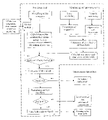
FIG. 1 illustrates the operating principle of the method according to the invention;
FIG. 2 is a schematic description of a static monitoring device;
FIG. 3 illustrates the performance under pressure of a pipe for which the solution can be implemented (the case of a reinforced concrete pipe);
FIG. 4 illustrates the different stages of pre-processing of the basic data allowing the value of the residual steel cross-section to be reached (illustrated for the case of static monitoring); and
FIG. 5 illustrates an updating process used in the method according to the invention.
The combination of the permanent monitoring techniques and the prediction tool constitutes the intelligent monitoring device (IMD) constituting the system according to the invention.
A pre-processing of the data produced by the permanent monitoring is necessary in order to retain only a limited amount of data (stiffness of the pipe K(ti) and its residual steel cross-section As(ti)) synthesizing the measurements taken over a defined period.
The prediction tool is built around physical laws (modelling of the corrosion and mechanical performance of the pipe) allowing determination, by means of a calculation, of an estimator of the residual steel cross-section A's(ti) and its evolution over time A's(t>ti).
The residual steel cross-section obtained by the monitoring system As(ti) is then compared, at regular intervals, with its estimator A's(ti). If the difference between these two values is greater than a precision E fixed in advance, the value of the measured residual steel cross-section As(ti) is used to update the corrosion model. This updating process allows recalculation of the estimator of the residual steel cross-section A's(ti) and its evolution over time A's(t>ti). The prediction tool is designed so as to be able to integrate, in the phase of updating the corrosion model, information coming from a source other than the static or dynamic monitoring (laboratory tests, visual inspections, number of failures, etc.).
Once the desired precision is obtained, the value of the measured residual steel cross-section As(ti) is compared with a limit criterion for mechanical strength CL. If the measured value is less than the criterion, it can be decided, for example, to undertake an immediate replacement of the instrumented section of pipe.
If the measured value of the residual steel cross-section As(ti) is greater than the limit criterion, the residual service life of the pipe D(ti) is determined using the evolution of the residual steel cross-section calculated by the prediction tool.
The following stage consists of comparing the value of the measured residual steel cross-section As(ti) with an alarm criterion CA associated with the mechanical strength. This time, if the measured value is less than the alarm criterion, a reinforcement of the instrumented section of pipe can, for example, be installed so as to defer the replacement.
If the measured value of the residual steel cross-section As(ti) is greater than the alarm criterion, the operating time before the alarm Da(ti) actuates is determined using the evolution of the residual steel cross-section calculated by the prediction tool. In these conditions, the maintenance operation would consist, for example, of doing nothing and the pipe would be left in that state.
A description will now be given, with reference to the figures mentioned above. A detailed description of an embodiment of the system according to the invention will now be given.
The static monitoring device is used in a limited number of singularity zones defined in advance. The objective of this device is to monitor, in singularity zones, the long term evolution of the longitudinal and circumferential deformations of the pipes.
For the purpose of making this static monitoring reliable, two types of sensors are to be provided. For example, a combination of standard strain measurement sensors (induction sensors) and fibre optic sensors measuring on bases of different lengths can be a possibility.
The longitudinal deformations serve mainly to verify the mechanical strength of the pipes (risk of bursting) in the event of accidental stresses (earthquakes, excess pressures). The circumferential deformations are used in normal operating conditions in the context of the solution allowing monitoring of the long term evolution of the residual steel cross-section, with reference to FIG. 3.
The dynamic monitoring device exploits the natural vibration of the pipes under pressure. It is designed to measure the displacement speeds at a defined number of points using seismometers. The objective of the dynamic monitoring device is to determine the vibration eigen modes of the pipe (modal deformation) and the associated frequencies.
The volume of raw data collected by the monitoring device increases according to the frequency of measurement. At regular intervals, it is necessary to undertake a pre-processing of this data in order to extract a limited number of values allowing the residual steel cross-section to be measured.
This pre-processing consists of calculating, using raw data (deformations, pressure, eigen frequencies, modal deformations):
    • an average deformation over a given period (for example: before, during and after a pressurization cycle);
    • the average eigen frequencies in the operating phase;
    • the stiffness K of the section of pipe over a given period, with reference to FIGS. 3 and 4;
    • the corresponding residual steel cross-section As.
The diagram of FIG. 4 allows illustration of the different stages of pre-processing in the case of the static monitoring. The laws which define the relationships between the deformations and the stiffness and between the stiffness and the residual steel cross-section are intrinsic characteristics of the instrumented pipe.
A similar diagram to that of FIG. 4 is made for the dynamic monitoring. In this case, the laws used allow definition of the relationship between an eigen frequency, the loss of stiffness of the zone concerned (this depends on the associated vibration mode) and the residual steel cross-section. These laws are also intrinsic characteristics of the instrumented pipe and are greatly dependent on the surface conditions of the pipe.
The different stages of pre-processing of the basic data allow the value of the residual steel cross-section to be reached, as FIG. 4 illustrates for the case of the static monitoring.
The following stage consists of comparing, at regular intervals, the residual steel cross-section obtained by the monitoring system As(ti) with its estimator A's(ti). If the difference between these two values is greater than a precision fixed in advance, the measured value of the residual steel cross-section As(ti) is used to update the corrosion model.
This update is based, among other things, on a Bayesian logic which allows improvement of the precision of the predictive model when ground data are available.
The updating process allows recalculation of the estimator of the residual steel cross-section A's(ti) and its evolution over time A's(t>ti).
The prediction tool is designed so as to be able to integrate, in the phase of updating the corrosion model, information coming from a source other than the static or dynamic monitoring (laboratory tests, visual inspections, number of failures, etc.).
Once the desired precision is obtained, the measured value of the residual steel cross-section As(ti) is compared with a limit criterion for mechanical strength CL. If the measured value is less than the criterion, it can be decided, for example, to undertake an immediate replacement of the instrumented section of pipe.
The following stage consists in comparing the measured value of the residual steel cross-section As(ti) with an alarm criterion CA associated with the mechanical strength. This time, if the measured value is less than the alarm criterion, a reinforcement of the instrumented section of pipe can, for example, be installed so as to defer the replacement.
If the measured value of the residual steel cross-section As(ti) is greater than the limit criterion, the residual service life of the pipe is determined using the evolution of the residual steel cross-section calculated by the prediction tool in the following manner, with reference to FIG. 5:
D(t i)=t(A s =CL)−t i
If the measured value of the residual steel cross-section As(ti) is greater than the alarm criterion, the operating time before the alarm Da(ti) is determined using the evolution of the residual steel cross-section calculated by the prediction tool in the following manner:
D a(t i)=t(A s =CA)−t i
When the measured value of the residual steel cross-section As(ti) is greater than the alarm criterion, the maintenance operation would consist, for example, of not doing anything and the pipe would be left in that state.
Of course, the invention is not limited to the examples which have just been described and numerous variations can be applied to these examples without going beyond the scope of the invention.

Claims (16)

1. A method for monitoring the performance of a pipe containing a pressurized fluid, this pipe comprising at least one continuous run zone and singularity zones, comprising:
a static monitoring of a predetermined number of singularity zones and/or continuous run zones, in order to provide circumferential expansion information,
a calculation of an effective stiffness K(ti) of the pipe and a measured residual steel cross-section As(ti) of the pipe using said circumferential expansion information,
predicting a temporal evolution A's(t>ti) of an estimator A's(ti) of the residual steel cross-section, this prediction being made on the basis of a model of corrosion and mechanical performance of the pipe,
comparing between the measured residual steel cross-section As(ti) and the estimator A's(ti) of the residual steel cross-section,
updating a corrosion model, when the difference between said measured residual steel cross-section As(ti) and said estimator of the residual steel cross-section A's(ti) is greater than a predetermined precision,
a comparison of the measured value As(ti) of the residual steel cross-section with a limit criterion of mechanical strength (CL), this comparison being followed by:
either a transmission of information for immediate replacement of a section of said pipe corresponding to the monitored zones, when this measured value As(ti) is less than said limit criterion for mechanical strength (CL),
or a calculation of the remaining service life D(ti) of said pipe, and
performing a maintenance operation on the pipe if said monitoring of the performance demonstrates the need for a maintenance operation.
2. The method according to claim 1, also comprising a dynamic monitoring of the pipe in order to provide information relating to the vibration eigen modes and frequencies of said pipe, and in that this information relating to eigen modes and frequencies is also used to calculate the stiffness K(ti) and the measured residual steel cross-section As(ti) of the pipe.
3. The method according to claim 2, also comprising:
a process of predicting a temporal evolution A's(t>ti) of an estimator A's(ti) of the residual steel cross-section, this prediction being made on the basis of a model of corrosion and mechanical performance of the pipe,
a comparison between the measured residual steel cross-section As(ti) and the estimator A's(ti) of the residual steel cross-section, and
an updating of a corrosion model, when the difference between said measured residual steel cross-section As(ti) and said estimator of the residual steel cross-section A's(ti) is greater than a predetermined precision.
4. The method according to claim 1, wherein the prediction process is organized so as to integrate, in a phase of updating the corrosion model, information coming from an external source.
5. The method according to claim 1, wherein the method also comprises a comparison of the measured value As(ti) of the residual steel cross-section with an alarm criterion (CA) associated with the mechanical strength of said pipe, this comparison being followed by:
either a transmission of information for reinforcement and subsequent replacement of a section of said pipe corresponding to the monitored zones, when this measured value As(ti) is less than said alarm criterion (CA),
or a calculation of operating time before the alarm Da(ti) of said pipe actuates.
6. A system for monitoring the performance of a pipe containing a pressurized fluid, this pipe comprising at least one continuous run zone and singularity zones, comprising:
a device for static monitoring of a predetermined number of singularity zones and/or continuous run zones in order to provide circumferential expansion information,
a calculator configured for calculating an effective stiffness K(ti) of the pipe and a measured residual steel cross-section As(ti) of the pipe using said circumferential expansion information,
a display configured for displaying the results of said monitoring,
a predictor configured for predicting a temporal evolution A's(t>ti) of an estimator A's(ti) of the residual steel cross-section, this prediction being made on the basis of a model of corrosion and mechanical performance of the pipe,
a comparator configured for comparing the measured residual steel cross-section As(ti) and the estimator A's(ti) of the residual steel cross-section,
an updater configured for updating a corrosion model, when the difference between said measured residual steel cross-section As(ti) and said estimator of the residual steel cross-section A's (ti) is greater than a predetermined precision, and
a value comparator configured for comparing the measured value As(ti) of the residual steel cross-section with a limit criterion of mechanical strength (CL), this comparison being followed by:
either a transmission of information for immediate replacement of a section of said pipe corresponding to the monitored zones, when this measured value As(ti) is less than said limit criterion for mechanical strength (CL),
or a calculation of the remaining service life D(ti) of said pipe.
7. The system according to claim 6, also comprising a dynamic monitoring device for dynamic monitoring of the pipe in order to provide information on eigen vibration modes and frequencies of said pipe, this information on eigen modes and frequencies being used by the calculator configured for calculation of an effective stiffness K(ti) and of a measured residual steel cross-section As(ti).
8. The system according to claim 6, wherein the static monitoring device comprises a longitudinal measuring apparatus configured for measuring longitudinal deformations of a section of the pipe and a circumferential measuring device configured for measuring circumferential deformations of said section.
9. The system according to claim 6, wherein the dynamic monitoring device comprises a seismometer for measuring displacement speeds at a predetermined number of points on the pipe.
10. The system according to claim 6, also comprising a pre-processing calculator configured for pre-processing raw data provided by the static and/or dynamic monitoring device, the preprocessing calculator being designed to calculate an average deformation over a given period and average eigen frequencies in the operating phase.
11. A system for monitoring the performance of a pipe containing a pressurized fluid, this pipe comprising at least one continuous run zone and singularity zones, comprising:
a device for static monitoring of a predetermined number of singularity zones and/or continuous run zones in order to provide circumferential expansion information;
a device for calculating an effective stiffness K(ti) of the pipe and a measured residual steel cross-section As(ti) of the pipe using said circumferential expansion information;
a device for displaying the results of said monitoring;
a device for predicting a temporal evolution A's(t>ti) of an estimator A's(ti) of the residual steel cross-section, this prediction being made on the basis of a model of corrosion and mechanical performance of the pipe;
a device for comparing the measured residual steel cross-section As(ti) and the estimator A's(ti) of the residual steel cross-section;
a device for updating a corrosion model, when the difference between said measured residual steel cross-section As(ti) and said estimator of the residual steel cross-section A's (ti) is greater than a predetermined precision; and
a device for comparing the measured value As(ti) of the residual steel cross-section with a limit criterion of mechanical strength (CL), this comparing being followed by:
either a transmission of information for immediate replacement of a section of said pipe corresponding to the monitored zones, when this measured value As(ti) is less than said limit criterion for mechanical strength (CL),
or a calculation of the remaining service life D(ti) of said pipe.
12. The system according to claim 11, also comprising a device for dynamic monitoring of the pipe in order to provide information on eigen vibration modes and frequencies of said pipe, this information on eigen modes and frequencies being used by the device for calculating the effective stiffness K(ti) and the measured residual steel cross-section As(ti).
13. The system according to claim 11, wherein the static monitoring device comprises a device for measuring longitudinal deformations of a section of the pipe and a device for measuring circumferential deformations of said section.
14. The system according to claim 11, wherein the dynamic monitoring device comprises a seismometer for measuring displacement speeds at a predetermined number of points on the pipe.
15. The system according to claim 11, also comprising a device for preprocessing raw data provided by the static and/or dynamic monitoring device, this pre-processing device being designed to calculate an average deformation over a given period and average eigen frequencies in the operating phase.
16. The system according to claim 11, also comprising:
a device for predicting a temporal evolution A's(t>ti) of an estimator A's(ti) of the residual steel cross-section, this prediction being made on the basis of a model of corrosion and mechanical performance of the pipe,
a device for comparing the measured residual steel cross-section As(ti) and the estimator A's(ti) of the residual steel cross-section, and
a device for updating a corrosion model, when the difference between said measured residual steel cross-section As(ti) and said estimator of the residual steel cross-section A's (ti) is greater than a predetermined precision.
US10/548,599 2003-03-11 2004-03-11 Method and system for monitoring the performance of a pipe containing a pressurised fluid Expired - Fee Related US7561976B2 (en)

Applications Claiming Priority (3)

Application Number Priority Date Filing Date Title
FR0302969A FR2852391B1 (en) 2003-03-11 2003-03-11 METHOD AND SYSTEM FOR MONITORING (MONITORING) THE BEHAVIOR OF PIPING CONTAINING PRESSURIZED FLUID
FR03/02969 2003-03-11
PCT/FR2004/000596 WO2004083969A2 (en) 2003-03-11 2004-03-11 Method and system for monitoring the performance of a pipe containing a pressurised fluid

Publications (2)

Publication Number Publication Date
US20060217902A1 US20060217902A1 (en) 2006-09-28
US7561976B2 true US7561976B2 (en) 2009-07-14

Family

ID=32893190

Family Applications (1)

Application Number Title Priority Date Filing Date
US10/548,599 Expired - Fee Related US7561976B2 (en) 2003-03-11 2004-03-11 Method and system for monitoring the performance of a pipe containing a pressurised fluid

Country Status (11)

Country Link
US (1) US7561976B2 (en)
EP (1) EP1604170B1 (en)
JP (1) JP4406638B2 (en)
KR (1) KR20060002809A (en)
CN (1) CN1784589B (en)
CA (1) CA2518697A1 (en)
ES (1) ES2543161T3 (en)
FR (1) FR2852391B1 (en)
RU (1) RU2351915C2 (en)
WO (1) WO2004083969A2 (en)
ZA (1) ZA200508092B (en)

Cited By (6)

* Cited by examiner, † Cited by third party
Publication number Priority date Publication date Assignee Title
US20100147056A1 (en) * 2008-12-12 2010-06-17 Stolle Joseph W Top of the Line Corrosion Apparatus
US20100262411A1 (en) * 2006-02-14 2010-10-14 Edsa Micro Corporation Systems and methods for real-time system monitoring and predictive analysis
US20170082526A1 (en) * 2014-03-19 2017-03-23 Bridgestone Corporation Method for predicting remaining life of hose and method for diagnosing deterioration level of hose
US10867087B2 (en) 2006-02-14 2020-12-15 Wavetech Global, Inc. Systems and methods for real-time DC microgrid power analytics for mission-critical power systems
US10962999B2 (en) 2009-10-01 2021-03-30 Wavetech Global Inc. Microgrid model based automated real time simulation for market based electric power system optimization
US11403446B1 (en) * 2021-05-19 2022-08-02 Guangzhou University Method, system and apparatus for predicting residual strength of composite material after impact, and medium

Families Citing this family (14)

* Cited by examiner, † Cited by third party
Publication number Priority date Publication date Assignee Title
DE102007028891A1 (en) * 2007-06-20 2009-01-15 Evonik Energy Services Gmbh Method for monitoring the stress of a pipeline section
US8589087B2 (en) * 2010-07-28 2013-11-19 General Electric Company Systems, methods, and apparatus for monitoring corrosion or corrosive contaminants associated with liquid fuel
GB2512835A (en) 2013-04-08 2014-10-15 Permasense Ltd Ultrasonic detection of a change in a surface of a wall
EP3117202B1 (en) 2014-03-14 2019-01-02 Rosemount Inc. Corrosion rate measurement
JP6589224B2 (en) * 2014-07-25 2019-10-16 国立大学法人鳥取大学 Tube evaluation method, measuring apparatus, and tube evaluation system
CN105371925A (en) * 2014-08-08 2016-03-02 北京谊安医疗系统股份有限公司 An anaesthesia machine flow sensor calibration method
US10830689B2 (en) 2014-09-30 2020-11-10 Rosemount Inc. Corrosion rate measurement using sacrificial probe
US10190968B2 (en) 2015-06-26 2019-01-29 Rosemount Inc. Corrosion rate measurement with multivariable sensor
JPWO2017078004A1 (en) * 2015-11-04 2018-09-13 日本電気株式会社 Piping status detection device, piping status detection method, computer-readable recording medium, and piping status detection system
CN106823082A (en) * 2016-12-06 2017-06-13 湖南明康中锦医疗科技发展有限公司 The method and lung ventilator of breathing machine maintenance management
JP7019401B2 (en) * 2017-12-15 2022-02-15 太平洋セメント株式会社 Cross-section reduction rate estimation method and load bearing capacity estimation method
DE102019135288A1 (en) * 2019-12-19 2021-06-24 Endress+Hauser Group Services Ag SYSTEM AND METHOD FOR MONITORING A CONDITION OF AT LEAST ONE OBJECT INCLUDED IN A PIPING SYSTEM
JP7770062B2 (en) * 2021-05-19 2025-11-14 アイエスアイエフ エス.アール.エル. Method for assessing the service condition of compensation joints.
CN114455805B (en) * 2021-12-20 2023-07-07 彩虹显示器件股份有限公司 A method and system for monitoring and controlling the operation of a substrate glass platinum channel

Citations (10)

* Cited by examiner, † Cited by third party
Publication number Priority date Publication date Assignee Title
DE3531975A1 (en) 1984-03-21 1987-03-19 Orgreb Inst Kraftwerke Method and arrangement for determining the wall thickness of cylindrical hollow bodies
EP0358994A1 (en) 1988-08-29 1990-03-21 Westinghouse Electric Corporation Corrosion-erosion trend monitoring and diagnostic system
JPH09145530A (en) 1995-11-20 1997-06-06 Mitsubishi Heavy Ind Ltd Fatigue evaluation apparatus for piping system
US6000277A (en) 1998-06-05 1999-12-14 Southwest Research Institute Method for the prediction of rupture in corroded transmission pipes subjected to combined loads
CN1376909A (en) 2001-03-23 2002-10-30 何凤歧 Gamma-ray detecting method and device for in-duty pipeline network
US6474165B1 (en) * 1997-12-12 2002-11-05 Severn Trent Water Limited Monitoring pipes
US6556924B1 (en) * 2000-07-27 2003-04-29 Hydroscope Canada Inc. Maintenance optimization system for water pipelines
US20050107963A1 (en) * 2002-03-02 2005-05-19 Robert Campbell Method for assessing the integrity of a structure
US6996913B2 (en) * 2004-01-29 2006-02-14 The Boeing Company Circumferential measurement of tubular members
US7181955B2 (en) * 2002-08-08 2007-02-27 Weatherford/Lamb, Inc. Apparatus and method for measuring multi-Phase flows in pulp and paper industry applications

Family Cites Families (4)

* Cited by examiner, † Cited by third party
Publication number Priority date Publication date Assignee Title
JPH0345530A (en) * 1989-07-13 1991-02-27 Shin Etsu Chem Co Ltd Production of high-viscosity silica glass
RU2111453C1 (en) * 1993-09-02 1998-05-20 Центральный научно-исследовательский институт "Гидроприбор" Multi-purpose diagnostic tool-flaw detector for checking pipeline for conditions
US5574223A (en) * 1994-04-05 1996-11-12 Gas Research Institute Scan assembly and method using scan rate modulation
RU2149394C1 (en) * 1999-09-07 2000-05-20 Чургель Анатолий Олегович Process and gear for ultrasonic diagnostics of pipes and pipe- lines

Patent Citations (11)

* Cited by examiner, † Cited by third party
Publication number Priority date Publication date Assignee Title
DE3531975A1 (en) 1984-03-21 1987-03-19 Orgreb Inst Kraftwerke Method and arrangement for determining the wall thickness of cylindrical hollow bodies
EP0358994A1 (en) 1988-08-29 1990-03-21 Westinghouse Electric Corporation Corrosion-erosion trend monitoring and diagnostic system
US4935195A (en) * 1988-08-29 1990-06-19 Westinghouse Electric Corp. Corrosion-erosion trend monitoring and diagnostic system
JPH09145530A (en) 1995-11-20 1997-06-06 Mitsubishi Heavy Ind Ltd Fatigue evaluation apparatus for piping system
US6474165B1 (en) * 1997-12-12 2002-11-05 Severn Trent Water Limited Monitoring pipes
US6000277A (en) 1998-06-05 1999-12-14 Southwest Research Institute Method for the prediction of rupture in corroded transmission pipes subjected to combined loads
US6556924B1 (en) * 2000-07-27 2003-04-29 Hydroscope Canada Inc. Maintenance optimization system for water pipelines
CN1376909A (en) 2001-03-23 2002-10-30 何凤歧 Gamma-ray detecting method and device for in-duty pipeline network
US20050107963A1 (en) * 2002-03-02 2005-05-19 Robert Campbell Method for assessing the integrity of a structure
US7181955B2 (en) * 2002-08-08 2007-02-27 Weatherford/Lamb, Inc. Apparatus and method for measuring multi-Phase flows in pulp and paper industry applications
US6996913B2 (en) * 2004-01-29 2006-02-14 The Boeing Company Circumferential measurement of tubular members

Non-Patent Citations (1)

* Cited by examiner, † Cited by third party
Title
Specification and drawings of U.S Appl. No. 60/402,491, filed on Aug. 8, 2002. *

Cited By (9)

* Cited by examiner, † Cited by third party
Publication number Priority date Publication date Assignee Title
US20100262411A1 (en) * 2006-02-14 2010-10-14 Edsa Micro Corporation Systems and methods for real-time system monitoring and predictive analysis
US8155908B2 (en) * 2006-02-14 2012-04-10 Power Analytics Corporation Systems and methods for real-time system monitoring and predictive analysis
US10867087B2 (en) 2006-02-14 2020-12-15 Wavetech Global, Inc. Systems and methods for real-time DC microgrid power analytics for mission-critical power systems
US20100147056A1 (en) * 2008-12-12 2010-06-17 Stolle Joseph W Top of the Line Corrosion Apparatus
US8261601B2 (en) 2008-12-12 2012-09-11 Exxonmobil Upstream Research Company Top of the line corrosion apparatus
US10962999B2 (en) 2009-10-01 2021-03-30 Wavetech Global Inc. Microgrid model based automated real time simulation for market based electric power system optimization
US20170082526A1 (en) * 2014-03-19 2017-03-23 Bridgestone Corporation Method for predicting remaining life of hose and method for diagnosing deterioration level of hose
US10006843B2 (en) * 2014-03-19 2018-06-26 Bridgestone Corporation Method for predicting remaining life of hose and method for diagnosing deterioration level of hose
US11403446B1 (en) * 2021-05-19 2022-08-02 Guangzhou University Method, system and apparatus for predicting residual strength of composite material after impact, and medium

Also Published As

Publication number Publication date
EP1604170B1 (en) 2015-05-06
RU2005131430A (en) 2006-02-10
ES2543161T3 (en) 2015-08-17
ZA200508092B (en) 2007-03-28
JP2006522324A (en) 2006-09-28
KR20060002809A (en) 2006-01-09
HK1086879A1 (en) 2006-09-29
WO2004083969A3 (en) 2004-11-18
US20060217902A1 (en) 2006-09-28
CA2518697A1 (en) 2004-09-30
JP4406638B2 (en) 2010-02-03
WO2004083969A2 (en) 2004-09-30
EP1604170A2 (en) 2005-12-14
CN1784589B (en) 2012-04-18
FR2852391B1 (en) 2005-09-09
RU2351915C2 (en) 2009-04-10
CN1784589A (en) 2006-06-07
FR2852391A1 (en) 2004-09-17

Similar Documents

Publication Publication Date Title
US7561976B2 (en) Method and system for monitoring the performance of a pipe containing a pressurised fluid
US20040243321A1 (en) System and method for pipeline reliability management
Noronha Jr et al. Procedures for the strain based assessment of pipeline dents
JP5423983B2 (en) Computer system and risk diagnosis method
EP3605050B1 (en) Pipe diagnosis device, asset management device and pipe diagnosis method.
CN120387383B (en) A trenchless repair design method for municipal drainage pipes and related equipment
CN119004046A (en) Air feed identification system based on data monitoring
CN101788399B (en) Health Monitoring Method of Cable System Based on Strain Monitoring with Bearing Settlement
KR20010079120A (en) automatic analysis method for tunnel lining stability monitoring at the maintenance stage
HK1086879B (en) Method and system for monitoring the performance of a pipe containing a pressurised fluid
KR100602832B1 (en) Amentment method of differential shortenint of vertical member in reinforced-concrete structures
CN120875558B (en) Bridge building prediction device and method based on BIM
CN121168293B (en) Thermodynamic pipeline security risk assessment method, thermodynamic pipeline security risk assessment system, thermodynamic pipeline security risk assessment equipment and thermodynamic pipeline security risk assessment program
CN120217208B (en) Performance evaluation method of friction pendulum isolation bearings in service
CN117688341B (en) Deep foundation pit detection system and method based on BIM technology
CN120446310B (en) Detection method and system for fire protection pipeline
Liu Seismic Assessment of Reinforced Concrete Structures Using Distributed Fiber-Optic Sensing
Xia et al. Structural monitoring of long-span curved reinforced concrete beam-column frame using distributed fibre optical sensor
Vorwagner et al. Possibilities of damage detection in reinforcement of retaining structures
Lee et al. Probabilistic fatigue life prediction for bridges using system reliability analysis and SHM-based finite element model updating
CN121188885A (en) Civil air defense engineering structure health evaluation method based on digital twinning
CN119312263A (en) A water supply management method and system
CN120257644A (en) Data twin-driven automotive precision shaft fault prediction system and method
CN120331879A (en) Support risk identification method and device for fault zone edge area
KR101141606B1 (en) Reverse analysis method for mixed deterioration by inverse bayesian belief networks modeling technique

Legal Events

Date Code Title Description
AS Assignment

Owner name: OXAND, FRANCE

Free format text: ASSIGNMENT OF ASSIGNORS INTEREST;ASSIGNORS:BERNARD, OLIVER;GERARD, BRUNO;REEL/FRAME:017778/0672

Effective date: 20050905

STCF Information on status: patent grant

Free format text: PATENTED CASE

AS Assignment

Owner name: OXAND, FRANCE

Free format text: CHANGE OF ADDRESS;ASSIGNOR:OXAND;REEL/FRAME:025363/0322

Effective date: 20101103

FPAY Fee payment

Year of fee payment: 4

FPAY Fee payment

Year of fee payment: 8

FEPP Fee payment procedure

Free format text: MAINTENANCE FEE REMINDER MAILED (ORIGINAL EVENT CODE: REM.); ENTITY STATUS OF PATENT OWNER: SMALL ENTITY

LAPS Lapse for failure to pay maintenance fees

Free format text: PATENT EXPIRED FOR FAILURE TO PAY MAINTENANCE FEES (ORIGINAL EVENT CODE: EXP.); ENTITY STATUS OF PATENT OWNER: SMALL ENTITY

STCH Information on status: patent discontinuation

Free format text: PATENT EXPIRED DUE TO NONPAYMENT OF MAINTENANCE FEES UNDER 37 CFR 1.362

FP Lapsed due to failure to pay maintenance fee

Effective date: 20210714