US7523986B2 - Child carrier attachments for bicycles - Google Patents
Child carrier attachments for bicycles Download PDFInfo
- Publication number
- US7523986B2 US7523986B2 US09/804,070 US80407001A US7523986B2 US 7523986 B2 US7523986 B2 US 7523986B2 US 80407001 A US80407001 A US 80407001A US 7523986 B2 US7523986 B2 US 7523986B2
- Authority
- US
- United States
- Prior art keywords
- bicycle
- support
- seat
- child
- child carrier
- Prior art date
- Legal status (The legal status is an assumption and is not a legal conclusion. Google has not performed a legal analysis and makes no representation as to the accuracy of the status listed.)
- Expired - Lifetime, expires
Links
Images


Classifications
-
- B—PERFORMING OPERATIONS; TRANSPORTING
- B62—LAND VEHICLES FOR TRAVELLING OTHERWISE THAN ON RAILS
- B62J—CYCLE SADDLES OR SEATS; AUXILIARY DEVICES OR ACCESSORIES SPECIALLY ADAPTED TO CYCLES AND NOT OTHERWISE PROVIDED FOR, e.g. ARTICLE CARRIERS OR CYCLE PROTECTORS
- B62J1/00—Saddles or other seats for cycles; Arrangement thereof; Component parts
- B62J1/28—Other additional equipment, e.g. back-rests for children
-
- B—PERFORMING OPERATIONS; TRANSPORTING
- B62—LAND VEHICLES FOR TRAVELLING OTHERWISE THAN ON RAILS
- B62J—CYCLE SADDLES OR SEATS; AUXILIARY DEVICES OR ACCESSORIES SPECIALLY ADAPTED TO CYCLES AND NOT OTHERWISE PROVIDED FOR, e.g. ARTICLE CARRIERS OR CYCLE PROTECTORS
- B62J1/00—Saddles or other seats for cycles; Arrangement thereof; Component parts
- B62J1/14—Separate pillions
- B62J1/16—Separate pillions for children
- B62J1/167—Child seats attachable in front of the driver saddle
Definitions
- the present invention relates to child carrier attachments for bicycles, and to bicycles provided with child carriers.
- the prior art also includes various proposals for mounting a child carrier between the saddle and the handle bars of the bicycle.
- This location of the seat has the advantages that the child can have a good view forwardly of the bicycle and is given a sense of security by being located between the arms of the rider, while the rider can observe the child.
- the present inventor has found, by practical experience, that it is desirable to be able to support the child carrier without attaching it to the horizontal cross-bar of a man's bicycle frame, because brake and derailleur cables usually extend along the horizontal cross-bar of a man's bicycle frame and, also, because the tubular components of bicycle frames vary considerably in diameter, length and angle.
- a bicycle carrier having an elongate support which is formed, at opposite ends, with notches for receiving the front post and the saddle post of a bicycle.
- This carrier is intended, in particular, to be attachable to a bicycle without the use of tools, and is provided at its rear end with a slidable rear member.
- the slidable rear member is formed with a notch for receiving the saddle post and is intended to be slid rearwardly, relative to the support, so as to locate the saddle post in the notch in the slidable rear member when the carrier is attached to a woman's bicycle.
- the slidable rear member When it is attached to a man's bicycle, the slidable rear member is removed.
- the support is mounted on the cross-bar of the man's bicycle, with projections on the underside of the support engaging the cross-bar, and with the notches in the opposite ends of the support slid into engagement with the front post and the saddle post of the bicycle.
- the carrier disclosed in the aforesaid U.S. Pat. No. 4,305,532 is particularly intended to be installed on and removed from a bicycle without the use of tool. When it is being installed onto a man's bicycle, therefore, it is simply pushed into position, and must therefore be of a predetermined length to fit a predetermined bicycle frame size.
- the notches at opposite ends of the carrier are of fixed width and are not adjustable to fit tubular bicycle components of various sizes. This prior art carrier is therefore not adjustable to fit bicycles of different sizes.
- the support is only loosely secured to the bicycle frame, and consequently there is a risk that it may easily be displaced from the frame when the bicycle it is for example subjected to an impact or a more or less violent movement by the child while in motion or when the rider of the bicycle is mounting or dismounting from the bicycle or when the rider is installing the child in, or removing the child from, the carrier.
- the rider must somehow support the bicycle while lifting a child into or from the carrier. This is often an awkward manoeuver, accomplished by leaning the bicycle against the riders body. The child will often wriggle while being lifted. It is therefore very important that the carrier should be fixedly connected to the bicycle instead of being only loosely attached.
- a child carrier attachment for a bicycle comprises a support device and a child seat mountable on the support device, the support device comprising an elongate support, and front and rear clamping devices on the elongate support, the rear fastener being adjustable into gripping engagement with a saddle post of the bicycle, the front fastener being adjustable into gripping engagement with a front post of the bicycle, and the support device being adjustable to vary the spacing of the front and rear fasteners.
- the support defines a longitudinally extending channel. The channel is positionable above and facing a top tube of the bicycle when the bicycle is a male-style bicycle.
- the support device can be adapted to different frame sizes by varying the spacing of the front and rear fasteners. Also, since the front and rear fasteners are engagable with the front post and the saddle post, respectively, of the bicycle, any brake and derailleur cables extending along the bicycle frame are not damaged by securement of the child carrier attachment to the bicycle and do not obstruct the securement of the child carrier attachment to the bicycle.
- the support is fixedly connectable to the bicycle and therefore cannot be dislodged by toppling of the bicycle or by movement of the bicycle and or of a child as the child is lifted into or from the carrier.
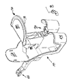
- FIG. 1 shows a view in perspective of a child carrier attachment embodying the present invention mounted on parts of a bicycle;
- FIG. 2 shows a view in side elevation of the child carrier attachment of FIG. 1 ;
- FIG. 3 shows an exploded view, in perspective, of components of a support device forming part of the child carrier attachment of FIGS. 1 and 2 ;
- FIG. 3A shows a view in perspective of a pair of spacers forming parts of a rear clamp shown in FIG. 3 ;
- FIG. 4 shows parts of the bicycle of FIG. 1 with the support device of FIG. 3 secured to it, but with other components of the child carrier attachment omitted;
- FIGS. 5A and 5B show views in perspective of a seat mounted in different positions on the support device of FIG. 3 ;
- FIG. 6 shows a view in vertical longitudinal cross-section through the child carrier attachment of FIG. 1 ;
- FIG. 7 shows an enlarged portion of FIG. 6 to illustrate interengagement of the headrest attachment and the seat
- FIG. 8 shows a view in perspective of the seat mounted on the support device and the headrest attachment mounted on the seat;
- FIG. 9 shows a view in perspective of the seat and the headrest attachment being being mounted on the support device on a bicycle frame
- FIG. 10 shows a broken-away view, in perspective, of parts of the headrest attachment and the seat secured together by a fastener.
- FIGS. 1 and 2 of the accompanying drawings show a child carrier attachment comprising a child's seat, indicated generally by reference numeral 10 , a headrest indicated generally by reference numeral 12 , and a support device indicated generally by reference numeral 14 .
- the support device 14 is, in turn, mounted on a bicycle frame a part of which is indicated generally by reference numeral 16 .
- the bicycle frame is male-style because there is top tube 19 .
- the support device 14 is shown in greater detail in FIG. 3 and comprises an elongate support formed by front and rear support bars 17 and 18 in the form of steel channel members having inverted U-shaped cross-sections. The channels of these members are positioned above and facing the top 19 of the bicycle frame.
- the rear support bar 18 has a front end 20 which is slidable within a rear end 22 of the front support bar 17 , and is provided at its rear end 24 with a rear or saddle post clamping device indicated generally by reference numeral 26 , while the front support bar 17 is provided, at its front end 28 , with a front or steering post clamping device indicated generally by reference numeral 30 .
- the rear end 24 of the rear support bar 18 is formed with two rearwardly projecting strip-shaped arms 32 , onto each of which fit a pair of resilient spacers 34 which are of hollow rectangular cross-section. As shown in FIG. 3A , the spacers 34 have opposite walls 35 and 37 , which have different thicknesses.
- a pair of threaded members in the form of bolts 36 extend through holes 38 in the arms 32 , through resiliently compressible cylindrical sleeves 40 positioned between the arms 32 and through washers 42 into threaded engagement with retainers in the form of nuts 44 .
- the bolts 36 can be tightened to bring the rear clamp 26 into gripping engagement with a saddle post 46 ( FIG. 2 ) installed in a gap between the spacers 34 on the arms 32 .
- a saddle post 46 FIG. 2
- the front support bar 17 is adjustably secured to the rear support bar 18 by means of a fastener comprising a hexagonal bolt 48 , a hexagonal nut 49 , an external tooth washer 50 and a fender washer 51 , the bolt 48 extending through a circular hole 52 in the front support bar 17 and through a longitudinal slot 54 in the rear support bar 18 .
- the support device 14 is adjustable, by relative longitudinal sliding of the front and rear support bars 17 and 18 , to vary the spacing between the front and rear clamps 30 and 26 .
- the front clamp 30 comprises a forwardly open yoke 56 formed on the front end 28 of the front support bar 17 and a U-clamp bracket 57 , opposite ends of which are secured to the arms of the yoke 56 by fasteners comprising screws 58 and nuts 60 , provided with external tooth washers 61 .
- Curved spacer members or collars 63 of resilient material are provided between the bracket 57 and the yoke 56 for gripping engagement with a head tube or steering post 62 forming part of the bicycle frame, and the thickness of these collars 63 may be selected to suit the diameter of the post 62 so as to ensure a tight fit. As can be seen in FIG.
- the front clamp 30 is angled, relative to the support bar 17 , to suit the inclination of the steering post 62 . This permits full surface contact between the collars 63 and the steering post 62 , thus providing a high clamping force and counteracting any risk of the support bar being deformed, dislodged or rotated under reasonable impact forces.
- FIG. 4 shows the support device 14 mounted on the bicycle frame 16 , with the rear fastener 26 in gripping engagement with the saddle post 46 and with the front fastener in gripping engagement with the front or steering post 62 of the bicycle frame 16 .
- the bicycle With the support device 14 thus secured to the bicycle frame 16 , the bicycle can be ridden without the seat 10 and the headrest attachment 12 .
- FIGS. 5A and 5B show the seat 10 mounted on, but not yet secured to, the support device 14 .
- the seat 10 is formed as a molding with a seat back 64 and with a pair of upwardly and laterally outwardly open foot boxes or foot rests 65 for receiving the feet and legs of a child on the seat to protect them. As shown, the foot rests 65 straddle the support device 14 .
- the width of the seat 10 is preferably limited to e.g. nine inches in order to avoid interference with the rider's legs.
- the seat 10 is formed with a slot 88 ( FIGS. 5A and 5B ) for receiving a bolt 68 , which extends through a washer 69 ( FIG. 9 ) and an opening 70 in the front support bar 17 into threaded engagement with a self-clinching fastener 71 ( FIG. 6 ).
- the fastener 71 which is manufactured and sold under the trade name PEM by Penn Engineering and Manufacturing Corp., is inserted into a hole in the front support bar 17 and then compressed, in known manner, into locking engagement with the front support bar 17 .
- the seat 10 is longitudinally adjustably secured to the support device 14 so as to be movable between a rearward position, relative to the front support bar, in which the seat is shown in FIG. 5A with the support device 14 fully extended, and a forward position, relative to the front support bar, as shown in FIG. 5B , which also shows the support device 14 fully extended.
- FIG. 7 shows the headrest attachment 12 during its assembly on the seat 10 .
- the headrest attachment 12 is formed with a pair of projecting tongues 72 which are engagable in slots 74 in the seat 10 , and also with a longitudinal slot.
- FIG. 8 shows the headrest attachment 12 mounted on the seat 10 which, in turn, is mounted in the support device 14
- FIG. 9 further shows these components in relation to the bicycle frame 16 .
- FIGS. 1 and 2 also illustrate a safety harness, indicated by reference numeral 76 , which is secured to the seat 10 .
- This safety harness 76 has been omitted from the other figures to facilitate illustration of the child carrier attachment.
- the safety harness 76 has a pair of shoulder straps 77 and a waist strap 79 .
- the waist strap 79 passes from within the seat 10 rearwardly through a pair of slots in the seat back 64 and then forwardly around the exterior of the seat back 64 through loops in the lower ends of the shoulder straps 77 to a waist buckle.
- This arrangement of the safety harness has been found to be particularly suitable for allowing the child sufficient slack to move comfortably and to rest on the headrest attachment 12 while also preventing the child from falling to the side of the seat 10 , and from standing or moving its body sideways sufficiently to adversely affect the balance and stability and control of the bicycle.
- the headrest attachment 12 comprises a forwardly and upwardly inclined tray 78 , on which a resilient pad 80 is retained by means of snap fasteners (not shown) to allow the child to rest its head on the headrest attachment 12 .
- the headrest attachment 12 is secured to the seat 10 by a bolt 82 , the head of which is received in a recess 84 ( FIG. 6 ) in the underside of the seat 10 , washers 85 and 86 and a nut 87 , and has a slot 88 which receives the bolt 68 so as to allow the headrest attachment 12 to be displaced together with the seat 10 when the latter is adjusted in position along the front support bar 17 as described above.
- the support device 14 and the seat 10 with its headrest 12 are fixedly secured to the bicycle frame 16 and cannot be dislodged, even if the bicycle falls sideways to the ground. Since the child occupying the seat 10 is restrained by the harness 76 , the child is thus securely held in position on the bicycle. If required, the bicycle can be ridden with the seat 10 and headrest 12 removed, in which case the support device 14 remains fixed in position on the bicycle frame 16 .
- the front and rear clamping devices 30 and 26 enable the support device 14 to be readily attached to a wide variety of bicycle frame tube diameters and the longitudinal adjustability of the support device 14 enables it to be attached to a wide variety of bicycle frame types and sizes.
- the present child carrier attachment can therefore be readily and securely mounted on a wide variety of men's and women's bicycles without interfering with brake and derailleur cables on the bicycle frames.
- the above-described attachment permits an interactive ride of the parent with the child with the objective of increasing the educational opportunities for the child and increasing the “bonding” between the parent and the child.
- the carrier is positioned such that the parent can readily observe the physical condition of the child and constantly monitor its changing needs.
- the child can be readily placed in or removed from the carrier with minimal risk of causing the bicycle to topple and the rider can readily mount or dismount from the bicycle with minimal risk of destabilizing the bicycle and causing the bicycle and its attached carrier to topple.
- the head support can support a resting child while the child is being transported in the child carrier and permits the adult rider to monitor the resting child and readily respond to the child's requirements.
- the child carrier is positioned so to minimize the effects of t/he child's weight or movement on the balance and stability/control of the bicycle.
- the child carrier can be easily and securely attached to its bicycle and readily transferred from bicycle to bicycle.
- the carrier attachment is applicable to the majority of adult leisure and recreational bicycles and does not interfere with the operation of brake and/or gear cables which may be on the bicycle.
- the secure attachment permits the child carrier to sustain a reasonable impact from any direction without causing the child carrier to be dislodged from its point(s) of attachment or causing the child carrier to rotate about any axis passing through the point(s) of attachment.
Abstract
Description
Claims (18)
Applications Claiming Priority (2)
| Application Number | Priority Date | Filing Date | Title |
|---|---|---|---|
| CA2,300,598 | 2000-03-14 | ||
| CA002300598A CA2300598A1 (en) | 2000-03-14 | 2000-03-14 | Bicycle seat with telescopic support bar |
Publications (2)
| Publication Number | Publication Date |
|---|---|
| US20040061361A1 US20040061361A1 (en) | 2004-04-01 |
| US7523986B2 true US7523986B2 (en) | 2009-04-28 |
Family
ID=4165503
Family Applications (1)
| Application Number | Title | Priority Date | Filing Date |
|---|---|---|---|
| US09/804,070 Expired - Lifetime US7523986B2 (en) | 2000-03-14 | 2001-03-13 | Child carrier attachments for bicycles |
Country Status (8)
| Country | Link |
|---|---|
| US (1) | US7523986B2 (en) |
| EP (1) | EP1263643A1 (en) |
| AU (1) | AU2001242143A1 (en) |
| CA (1) | CA2300598A1 (en) |
| CZ (1) | CZ20023091A3 (en) |
| IL (1) | IL151738A0 (en) |
| MX (1) | MXPA02008994A (en) |
| WO (1) | WO2001068438A1 (en) |
Cited By (6)
| Publication number | Priority date | Publication date | Assignee | Title |
|---|---|---|---|---|
| US9751579B2 (en) * | 2016-05-04 | 2017-09-05 | Mega Productions Co., Ltd. | Child bicycle seat |
| US20180057088A1 (en) * | 2016-08-30 | 2018-03-01 | Thule Sweden Ab | Child Bike Seat |
| US10266224B2 (en) | 2015-11-10 | 2019-04-23 | Kent International Inc. | Mounting bar, mounting bracket, and kit for use with a bicycle |
| US20190217911A1 (en) * | 2018-01-12 | 2019-07-18 | Beto Engineering and Marketing Co., Ltd. | Baby seat of bicycle |
| US11102954B2 (en) * | 2019-11-15 | 2021-08-31 | Chris Jensen | Bicycle-mounted platform and brace for pet transport |
| US11352085B2 (en) | 2020-01-10 | 2022-06-07 | Thule Sweden Ab | Child bike seat and method of assembling a child bike seat |
Families Citing this family (13)
| Publication number | Priority date | Publication date | Assignee | Title |
|---|---|---|---|---|
| GB2367544B (en) * | 2000-10-06 | 2004-02-25 | David Godden | Cycle with integrated load platform |
| US20050001460A1 (en) * | 2003-07-02 | 2005-01-06 | Jessica Starodoj | Child passenger carrier for bicycles |
| CA2471149A1 (en) * | 2004-06-11 | 2005-12-11 | Malcolm Jefferson | Carrier for attachment to a bicycle |
| DE102005051962B3 (en) * | 2005-10-29 | 2007-02-08 | Heinz Dr. Nagel | Home exercise bike has fixed handle fitted with removable child seat which can be set in vibration through drive assembly |
| EP1998646A4 (en) * | 2006-03-28 | 2011-01-12 | Matthew Kagan | User interface support, and chair in combination therewith |
| FR2943614A1 (en) * | 2009-03-27 | 2010-10-01 | Francois Pierre Andre Coubris | Accessory for baby seat at rear side of bicycle of adult e.g. parents, has inner and outer toothed attachment clamps fixing arm to another arm, which is maintained by corner clamp with tube of saddle of adult bicycle |
| AT508520B1 (en) * | 2009-08-12 | 2011-07-15 | Mario Gromes | CHILD SEAT |
| US9505457B2 (en) | 2013-09-04 | 2016-11-29 | Ritchie James Buttle | Auxiliary child bicycle seat |
| CN103612693A (en) * | 2013-12-10 | 2014-03-05 | 谢文娟 | Bicycle child seat |
| US9314113B1 (en) | 2015-01-15 | 2016-04-19 | Lisbeth Hals Lehan | Child carrier having adjustable seat coupling |
| CN105774964B (en) * | 2016-04-25 | 2018-07-31 | 丁存保 | A kind of preposition rumble seat of electric bicycle children |
| CN107651057A (en) * | 2017-08-14 | 2018-02-02 | 深圳市瑞德思维科技有限公司 | Axle attachment |
| BR102021018953A2 (en) * | 2021-09-23 | 2023-04-04 | Cesar Augusto De Mello Rippel | ADDITIONAL SEAT STRUCTURE FOR ELECTRIC BICYCLES |
Citations (19)
| Publication number | Priority date | Publication date | Assignee | Title |
|---|---|---|---|---|
| US453212A (en) * | 1891-06-02 | -sager | ||
| US460031A (en) * | 1891-09-22 | Seat attachment for bicycles | ||
| US3515431A (en) | 1968-04-29 | 1970-06-02 | Maurice J Grady | Vehicle seat for children |
| US3738704A (en) | 1971-07-26 | 1973-06-12 | L Smith | Auxiliary bicycle seat |
| US3902737A (en) * | 1974-02-04 | 1975-09-02 | Sears Roebuck & Co | Child carrier and mounting assembly for bicycle |
| US4305532A (en) * | 1979-07-20 | 1981-12-15 | Reminger John F | Universal bicycle carrier |
| US4632453A (en) | 1984-10-15 | 1986-12-30 | Robbin John D | Auxiliary support system for bicycle passenger |
| USD291506S (en) | 1985-03-29 | 1987-08-25 | Lorne Shields | Child's chair for attachment to a bicycle |
| US4919479A (en) | 1987-08-20 | 1990-04-24 | Loewke Eunice R | Apparatus for carrying a passenger on a bicycle |
| US4964551A (en) | 1989-03-28 | 1990-10-23 | Cycle Products Company | Bicycle child carrier assembly |
| US4969658A (en) | 1989-06-05 | 1990-11-13 | Mathias Levarek | Child's bicycle seat |
| US5104188A (en) | 1988-09-26 | 1992-04-14 | Malcolm Jefferson | Bicycle seat for children |
| US5149112A (en) * | 1989-12-27 | 1992-09-22 | Kidz First, Inc. | Bicycle conversion bar |
| US5330215A (en) * | 1993-01-28 | 1994-07-19 | All American Products, Inc. | Center-mounted passenger seat for bicycle |
| JPH07269543A (en) * | 1994-03-28 | 1995-10-17 | Seiko Epson Corp | Structure of screw |
| US5467906A (en) * | 1992-08-17 | 1995-11-21 | Forman; Mark L. | Camera bicycle |
| US5927801A (en) * | 1998-02-17 | 1999-07-27 | Miree; Mallory F. | Auxiliary bicycle seat |
| US6264223B1 (en) * | 2000-02-22 | 2001-07-24 | Eunice R. Loewke | Passenger carrier for bicycle |
| US6435523B1 (en) * | 2000-07-14 | 2002-08-20 | Yakima Products, Inc. | Surrogate top tube |
-
2000
- 2000-03-14 CA CA002300598A patent/CA2300598A1/en not_active Abandoned
-
2001
- 2001-03-13 EP EP01914872A patent/EP1263643A1/en not_active Withdrawn
- 2001-03-13 US US09/804,070 patent/US7523986B2/en not_active Expired - Lifetime
- 2001-03-13 CZ CZ20023091A patent/CZ20023091A3/en unknown
- 2001-03-13 MX MXPA02008994A patent/MXPA02008994A/en unknown
- 2001-03-13 WO PCT/CA2001/000322 patent/WO2001068438A1/en not_active Application Discontinuation
- 2001-03-13 IL IL15173801A patent/IL151738A0/en unknown
- 2001-03-13 AU AU2001242143A patent/AU2001242143A1/en not_active Abandoned
Patent Citations (19)
| Publication number | Priority date | Publication date | Assignee | Title |
|---|---|---|---|---|
| US453212A (en) * | 1891-06-02 | -sager | ||
| US460031A (en) * | 1891-09-22 | Seat attachment for bicycles | ||
| US3515431A (en) | 1968-04-29 | 1970-06-02 | Maurice J Grady | Vehicle seat for children |
| US3738704A (en) | 1971-07-26 | 1973-06-12 | L Smith | Auxiliary bicycle seat |
| US3902737A (en) * | 1974-02-04 | 1975-09-02 | Sears Roebuck & Co | Child carrier and mounting assembly for bicycle |
| US4305532A (en) * | 1979-07-20 | 1981-12-15 | Reminger John F | Universal bicycle carrier |
| US4632453A (en) | 1984-10-15 | 1986-12-30 | Robbin John D | Auxiliary support system for bicycle passenger |
| USD291506S (en) | 1985-03-29 | 1987-08-25 | Lorne Shields | Child's chair for attachment to a bicycle |
| US4919479A (en) | 1987-08-20 | 1990-04-24 | Loewke Eunice R | Apparatus for carrying a passenger on a bicycle |
| US5104188A (en) | 1988-09-26 | 1992-04-14 | Malcolm Jefferson | Bicycle seat for children |
| US4964551A (en) | 1989-03-28 | 1990-10-23 | Cycle Products Company | Bicycle child carrier assembly |
| US4969658A (en) | 1989-06-05 | 1990-11-13 | Mathias Levarek | Child's bicycle seat |
| US5149112A (en) * | 1989-12-27 | 1992-09-22 | Kidz First, Inc. | Bicycle conversion bar |
| US5467906A (en) * | 1992-08-17 | 1995-11-21 | Forman; Mark L. | Camera bicycle |
| US5330215A (en) * | 1993-01-28 | 1994-07-19 | All American Products, Inc. | Center-mounted passenger seat for bicycle |
| JPH07269543A (en) * | 1994-03-28 | 1995-10-17 | Seiko Epson Corp | Structure of screw |
| US5927801A (en) * | 1998-02-17 | 1999-07-27 | Miree; Mallory F. | Auxiliary bicycle seat |
| US6264223B1 (en) * | 2000-02-22 | 2001-07-24 | Eunice R. Loewke | Passenger carrier for bicycle |
| US6435523B1 (en) * | 2000-07-14 | 2002-08-20 | Yakima Products, Inc. | Surrogate top tube |
Cited By (9)
| Publication number | Priority date | Publication date | Assignee | Title |
|---|---|---|---|---|
| US10266224B2 (en) | 2015-11-10 | 2019-04-23 | Kent International Inc. | Mounting bar, mounting bracket, and kit for use with a bicycle |
| US10814929B2 (en) | 2015-11-10 | 2020-10-27 | Kent International Inc. | Mounting bar, mounting bracket, and kit for use with a bicycle |
| US9751579B2 (en) * | 2016-05-04 | 2017-09-05 | Mega Productions Co., Ltd. | Child bicycle seat |
| US20180057088A1 (en) * | 2016-08-30 | 2018-03-01 | Thule Sweden Ab | Child Bike Seat |
| US10654539B2 (en) * | 2016-08-30 | 2020-05-19 | Thule Sweden Ab | Child bike seat |
| US20190217911A1 (en) * | 2018-01-12 | 2019-07-18 | Beto Engineering and Marketing Co., Ltd. | Baby seat of bicycle |
| US10472014B2 (en) * | 2018-01-12 | 2019-11-12 | Beto Engineering and Marketing Co., Ltd. | Baby seat of bicycle |
| US11102954B2 (en) * | 2019-11-15 | 2021-08-31 | Chris Jensen | Bicycle-mounted platform and brace for pet transport |
| US11352085B2 (en) | 2020-01-10 | 2022-06-07 | Thule Sweden Ab | Child bike seat and method of assembling a child bike seat |
Also Published As
| Publication number | Publication date |
|---|---|
| CZ20023091A3 (en) | 2003-08-13 |
| WO2001068438A1 (en) | 2001-09-20 |
| CA2300598A1 (en) | 2001-09-14 |
| MXPA02008994A (en) | 2004-10-15 |
| US20040061361A1 (en) | 2004-04-01 |
| IL151738A0 (en) | 2003-04-10 |
| EP1263643A1 (en) | 2002-12-11 |
| AU2001242143A1 (en) | 2001-09-24 |
Similar Documents
| Publication | Publication Date | Title |
|---|---|---|
| US7523986B2 (en) | Child carrier attachments for bicycles | |
| US5190346A (en) | Adjustable wraparound bicycle seat post clamping apparatus with a single fastener | |
| EP1056637B1 (en) | Auxiliary bicycle seat | |
| US20020011745A1 (en) | Adjustable back rest and cargo carrier for a motorcycle | |
| US5207361A (en) | Easily detachable carrier attachment for a vehicle | |
| US6988645B1 (en) | Bicycle rack anti-sway stabilizer | |
| CA2471149A1 (en) | Carrier for attachment to a bicycle | |
| EP0390332A2 (en) | Bicycle child carrier assembly | |
| US5330215A (en) | Center-mounted passenger seat for bicycle | |
| EP3374251B1 (en) | Mounting bar, mounting bracket, and kit for use with a bicycle | |
| US7360819B1 (en) | Quick-release motorcycle windshield | |
| US7934741B1 (en) | Safety bar device for motorcycles | |
| US6010140A (en) | Child bicycle seat and training system | |
| GB2303344A (en) | Vehicle roof rack | |
| US10513299B2 (en) | Adjustable bicycle rack | |
| US3486727A (en) | Support means for a saddle | |
| US5800014A (en) | Adjustable child seat for bicycles | |
| EP4124549A1 (en) | Attachable bag for bicycle | |
| CA2340537A1 (en) | Child carrier attachments for bicycles | |
| US6126052A (en) | Canoe carrier system | |
| US20050253428A1 (en) | Child passenger carrier for bicycles | |
| US4928863A (en) | Bicycle rack for carrying sport boards | |
| US6688622B2 (en) | Bicycle transporter | |
| WO2009018604A1 (en) | Bicycle transport support | |
| EP3556642B1 (en) | Portable lock mounting assemblies |
Legal Events
| Date | Code | Title | Description |
|---|---|---|---|
| AS | Assignment |
Owner name: CENTRIC-SAFE HAVEN INC., CANADA Free format text: ASSIGNMENT OF ASSIGNORS INTEREST;ASSIGNORS:JEFFERSON, MALCOLM;BARNWELL, BRIAN;BACK, TERENCE NORMAN, (DECEASED) BY HIS LEGAL ADMINISTRATOR, JOSEPHINE BACK;REEL/FRAME:014749/0389;SIGNING DATES FROM 20031020 TO 20031021 |
|
| AS | Assignment |
Owner name: 2083461 ONTARIO INC., CANADA Free format text: JUDGMENT;ASSIGNOR:CENTRIC-SAFE HAVEN INC.;REEL/FRAME:019347/0840 Effective date: 20070511 |
|
| STCF | Information on status: patent grant |
Free format text: PATENTED CASE |
|
| CC | Certificate of correction | ||
| FPAY | Fee payment |
Year of fee payment: 4 |
|
| FEPP | Fee payment procedure |
Free format text: PAYOR NUMBER ASSIGNED (ORIGINAL EVENT CODE: ASPN); ENTITY STATUS OF PATENT OWNER: SMALL ENTITY |
|
| AS | Assignment |
Owner name: WELLS FARGO BANK, NATIONAL ASSOCIATION, NEW YORK Free format text: PATENT COLLATERAL ASSIGNMENT AND SECURITY AGREEMENT;ASSIGNOR:KENT INTERNATIONAL INC.;REEL/FRAME:037444/0735 Effective date: 20151217 |
|
| FPAY | Fee payment |
Year of fee payment: 8 |
|
| AS | Assignment |
Owner name: KENT INTERNATIONAL INC., NEW JERSEY Free format text: RELEASE OF SECURITY INTEREST IN PATENTS;ASSIGNOR:WELLS FARGO BANK, NATIONAL ASSOCIATION;REEL/FRAME:051109/0830 Effective date: 20191122 |
|
| MAFP | Maintenance fee payment |
Free format text: PAYMENT OF MAINTENANCE FEE, 12TH YR, SMALL ENTITY (ORIGINAL EVENT CODE: M2553); ENTITY STATUS OF PATENT OWNER: SMALL ENTITY Year of fee payment: 12 |