US7513759B1 - Valve guide and spring retainer assemblies - Google Patents
Valve guide and spring retainer assemblies Download PDFInfo
- Publication number
- US7513759B1 US7513759B1 US11/125,282 US12528205A US7513759B1 US 7513759 B1 US7513759 B1 US 7513759B1 US 12528205 A US12528205 A US 12528205A US 7513759 B1 US7513759 B1 US 7513759B1
- Authority
- US
- United States
- Prior art keywords
- bore
- suction
- transition area
- discharge
- valve
- Prior art date
- Legal status (The legal status is an assumption and is not a legal conclusion. Google has not performed a legal analysis and makes no representation as to the accuracy of the status listed.)
- Active, expires
Links
- 230000000712 assembly Effects 0.000 title abstract description 14
- 238000000429 assembly Methods 0.000 title abstract description 14
- 230000007704 transition Effects 0.000 claims description 79
- 238000012856 packing Methods 0.000 claims description 12
- 125000006850 spacer group Chemical group 0.000 abstract description 60
- 230000009467 reduction Effects 0.000 abstract description 4
- 238000003780 insertion Methods 0.000 description 25
- 230000037431 insertion Effects 0.000 description 25
- 239000012530 fluid Substances 0.000 description 17
- 230000002093 peripheral effect Effects 0.000 description 15
- 238000013461 design Methods 0.000 description 13
- 230000033001 locomotion Effects 0.000 description 12
- 230000013011 mating Effects 0.000 description 7
- 238000012423 maintenance Methods 0.000 description 5
- 238000009434 installation Methods 0.000 description 4
- 230000008901 benefit Effects 0.000 description 3
- 238000003754 machining Methods 0.000 description 3
- 238000004519 manufacturing process Methods 0.000 description 3
- 230000004308 accommodation Effects 0.000 description 2
- 230000001154 acute effect Effects 0.000 description 2
- 230000006835 compression Effects 0.000 description 2
- 238000007906 compression Methods 0.000 description 2
- 235000009967 Erodium cicutarium Nutrition 0.000 description 1
- 240000003759 Erodium cicutarium Species 0.000 description 1
- 230000005540 biological transmission Effects 0.000 description 1
- 238000005336 cracking Methods 0.000 description 1
- 230000003247 decreasing effect Effects 0.000 description 1
- 238000006073 displacement reaction Methods 0.000 description 1
- 230000000694 effects Effects 0.000 description 1
- 238000009499 grossing Methods 0.000 description 1
- 238000005259 measurement Methods 0.000 description 1
- 238000000034 method Methods 0.000 description 1
- 230000003252 repetitive effect Effects 0.000 description 1
Images


Classifications
-
- F—MECHANICAL ENGINEERING; LIGHTING; HEATING; WEAPONS; BLASTING
- F04—POSITIVE - DISPLACEMENT MACHINES FOR LIQUIDS; PUMPS FOR LIQUIDS OR ELASTIC FLUIDS
- F04B—POSITIVE-DISPLACEMENT MACHINES FOR LIQUIDS; PUMPS
- F04B53/00—Component parts, details or accessories not provided for in, or of interest apart from, groups F04B1/00 - F04B23/00 or F04B39/00 - F04B47/00
- F04B53/007—Cylinder heads
-
- F—MECHANICAL ENGINEERING; LIGHTING; HEATING; WEAPONS; BLASTING
- F04—POSITIVE - DISPLACEMENT MACHINES FOR LIQUIDS; PUMPS FOR LIQUIDS OR ELASTIC FLUIDS
- F04B—POSITIVE-DISPLACEMENT MACHINES FOR LIQUIDS; PUMPS
- F04B53/00—Component parts, details or accessories not provided for in, or of interest apart from, groups F04B1/00 - F04B23/00 or F04B39/00 - F04B47/00
- F04B53/10—Valves; Arrangement of valves
- F04B53/102—Disc valves
- F04B53/1032—Spring-actuated disc valves
-
- F—MECHANICAL ENGINEERING; LIGHTING; HEATING; WEAPONS; BLASTING
- F04—POSITIVE - DISPLACEMENT MACHINES FOR LIQUIDS; PUMPS FOR LIQUIDS OR ELASTIC FLUIDS
- F04B—POSITIVE-DISPLACEMENT MACHINES FOR LIQUIDS; PUMPS
- F04B53/00—Component parts, details or accessories not provided for in, or of interest apart from, groups F04B1/00 - F04B23/00 or F04B39/00 - F04B47/00
- F04B53/16—Casings; Cylinders; Cylinder liners or heads; Fluid connections
- F04B53/162—Adaptations of cylinders
- F04B53/164—Stoffing boxes
-
- Y—GENERAL TAGGING OF NEW TECHNOLOGICAL DEVELOPMENTS; GENERAL TAGGING OF CROSS-SECTIONAL TECHNOLOGIES SPANNING OVER SEVERAL SECTIONS OF THE IPC; TECHNICAL SUBJECTS COVERED BY FORMER USPC CROSS-REFERENCE ART COLLECTIONS [XRACs] AND DIGESTS
- Y10—TECHNICAL SUBJECTS COVERED BY FORMER USPC
- Y10T—TECHNICAL SUBJECTS COVERED BY FORMER US CLASSIFICATION
- Y10T137/00—Fluid handling
- Y10T137/7722—Line condition change responsive valves
- Y10T137/7837—Direct response valves [i.e., check valve type]
- Y10T137/7838—Plural
Definitions
- the invention relates generally to high-pressure plunger pumps used, for example, in oil field operations. More particularly, the invention relates to valve guides and spring retainers for use in plunger pump housings that incorporate structural features for stress-relief and for accommodating valve guide and/or spring retainer assemblies.
- FIG. 1 is a cross-sectional schematic view of a typical fluid section showing its connection to a power section by stay rods. A plurality of fluid sections similar to that illustrated in FIG. 1 may be combined, as suggested in the Triplex fluid section housing schematically illustrated in FIG. 2 .
- Valve terminology varies according to the industry (e.g., pipeline or oil field service) in which the valve is used.
- the term “valve” means just the moving element or valve body.
- the term “valve” includes other components in addition to the valve body (e.g., various valve guides to control the motion of the valve body, the valve seat, and/or one or more valve springs that tend to hold the valve closed, with the valve body reversibly sealed against the valve seat).
- Each individual bore in a plunger pump housing is subject to fatigue due to alternating high and low pressures which occur with each stroke of the plunger cycle.
- Conventional plunger pump housings typically fail due to fatigue cracks in one of the areas defined by the intersecting suction, plunger, access and discharge bores as schematically illustrated in FIG. 3 .
- a Y-block housing design has been proposed.
- the Y-block design which is schematically illustrated in FIG. 4 , reduces stress concentrations in a plunger pump housing such as that shown in FIG. 3 by increasing the angles of bore intersections above 90°. In the illustrated example of FIG. 4 , the bore intersection angles are approximately 120°.
- a more complete cross-sectional view of a Y-block plunger pump fluid section is schematically illustrated in FIG. 5 .
- FIG. 6 One embodiment of a right angular plunger pump such as that described in U.S. Pat. No. 6,623,259 (hereinafter the '259 patent) is schematically illustrated in FIG. 6 . It includes a right-angular plunger pump housing comprising a suction valve bore (suction bore), discharge valve bore (discharge bore), plunger bore and access bore.
- the suction and discharge bores each have a portion with substantially circular cross-sections for accommodating, e.g., a valve seat.
- a valve seat e.g., a valve seat
- the illustrated portions of the suction and discharge bores that accommodate a valve seat are slightly conical to facilitate substantially leak-proof and secure placement of each valve seat in the pump housing (e.g., by press-fitting a valve seat that has an interference fit with the pump housing).
- the portions of suction and discharge bores intended to accommodate a valve seat are cylindrical instead of being slightly conical.
- each bore i.e., suction, discharge, access and plunger bores
- each bore comprises a transition area which interfaces with other bore transition areas.
- the plunger bore of the right-angular plunger pump housing of FIG. 6 comprises a plunger bore having a proximal packing area (i.e., an area relatively nearer the power section) and a distal transition area (i.e., an area relatively more distant from the power section). Between the packing and transition areas is a right circular cylindrical area for accommodating a plunger. The transition area of the plunger bore facilitates interfaces with analogous transition areas of other bores as noted above.
- Each bore transition area of the right-angular pump housing of FIG. 6 has a stress-reducing feature comprising an elongated (e.g., elliptical or oblong) cross-section that is substantially perpendicular to each respective bore's longitudinal axis. Intersections of the bore transition areas are chamfered, the chamfers comprising additional stress-reducing features. Further, the long axis of each such elongated cross-section is substantially perpendicular to a plane that contains, or is parallel to, the longitudinal axes of the suction, discharge, access and plunger bores.
- An elongated suction bore transition area can simplify certain plunger pump housing structural features needed for installation of a suction valve.
- the valve spring retainer of a suction valve installed in such a plunger pump housing does not require a retainer arm projecting from the housing.
- threads have to be cut in the housing to position the retainer that secures the suction valve seat.
- Benefits arising from the absence of a suction valve spring retainer arm include stress reduction in the plunger pump housing and simplified machining requirements.
- the absence of threads associated with a suction valve seat retainer in the suction bore eliminates the stress-concentrating effects that would otherwise be associated with such threads.
- Threads can be eliminated from the suction bore if the suction valve seat is inserted via the access bore and the suction bore transition area and press-fit into place as described in the '259 patent.
- the suction valve body can also be inserted via the access bore and the suction bore transition area.
- a valve spring is inserted via the access bore and the suction bore transition area and held in place by a similarly-inserted oblong suction valve spring retainer, an example of which is described in the '259 patent.
- the '259 patent illustrates an oblong suction valve spring retainer having a guide hole (for a top-stem-guided valve body), as well as an oblong suction valve spring retainer without a guide hole (for a crow-foot-guided valve body).
- Both of these oblong suction valve spring retainer embodiments are secured in a pump housing of the '259 patent by clamping about an oblong lip, the lip being a structural feature of the housing (see FIG. 6 for a schematic illustration of oblong lip 266 in a right angular plunger pump housing).
- the '259 patent also shows how discharge valves can be mounted in the fluid end of a high-pressure pump incorporating positive displacement pistons or plungers.
- suction and discharge valves typically incorporate a traditional full open seat design with each valve body having integral crow-foot guides. This design has been adapted for the high pressures and repetitive impact loading of the valve body and valve seat that are seen in well service.
- stem-guided valves with full open seats could also be considered for well service because they offer better flow characteristics than traditional crow-foot-guided valves.
- stem-guided valves may have guide stems on both sides of the valve body (i.e., “top” and “lower” guide stems) or only on one side of the valve body (e.g., as in top stem guided valves) to maintain proper alignment of the valve body with the valve seat during opening and closing.
- Conventional valve designs incorporating secure placement of guides for both top and lower valve guide stems have been associated with complex components and difficult maintenance.
- plunger pump housings incorporate one or more of the stress-relief structural features described herein, plus one or more additional structural features associated with use of alternative valve stem guide and spring retainer assemblies in the housings.
- Such plunger pump housings do not, however, comprise an oblong lip (see, e.g., structure 266 in FIG. 6 as noted above) for securing a suction valve spring retainer. The absence of this oblong lip simplifies machining of the plunger pump housing, and the corresponding design results in reduced stress within the pump housing.
- valve stem guide and spring retainer assemblies include, for example, a combination comprising a discharge valve lower stem guide (DVLSG), plus a suction valve top stem guide and spring retainer (SVTSG-SR), plus spacers for spacing the DVLSG a predetermined distance apart from the SVTSG-SR.
- Alternative embodiments comprise other combinations of structural features such as, for example, spring retainers and spacers with or without associated valve guides. Note that due to the close fit of the DVLSG within the discharge bore and of the SVTSG-SR within the suction bore, insertion or removal of these structures requires maintaining precise alignment as to rotation and angle of entry with their respective bores. Such precise alignment may be difficult to maintain during field service operations.
- the present invention includes improved valve guide and spring retainer assemblies for use in plunger pump housings having an outwardly flared transition area in the suction bore.
- Alternative valve guide and spring retainer assemblies of the present invention are for use in plunger pump housings having an outwardly flared transition area in the discharge bore as well as the suction bore. Note that an outwardly flared transition area in the suction bore (together with an outwardly flared transition area in the discharge bore in alternative embodiments) allows relatively easier insertion and removal of portions of improved valve guides and spring retainer assemblies in these areas.
- an embodiment of an improved valve guide and spring retainer assembly of the present invention comprises a tapered suction valve top stem guide and spring retainer (hereinafter an SVTSG-SR-II), as well as a tapered discharge valve lower stem guide (hereinafter DVLSG-II), together with at least one side spacer.
- SVTSG-SR-II tapered suction valve top stem guide and spring retainer
- DVLSG-II tapered discharge valve lower stem guide
- each side spacer contacts the DVLSG-II (along a discharge lateral alignment lip) and the SVTSG-SR-II (along an opposing suction lateral alignment lip) to transmit the suction valve spring force acting on the SVTSG-SR-II to a shoulder in the discharge bore.
- the DVLSG-II simultaneously acts as a guide for the discharge valve lower guide stem.
- the side spacer(s) must be free to move laterally (i.e., vertical movement toward the discharge bore as shown in the illustrated embodiments) during installation of opposing suction and discharge valves in a pump housing.
- Such lateral side spacer movement ends on contact of the DVLSG-II with the discharge bore shoulder; this contact being maintained thereafter by the compressive force of the suction valve spring as transmitted to the DVLSG-II via the side spacer(s).
- longitudinal movement of each side spacer is limited by the access bore plug on one end of the spacer and by a plunger bore shoulder on the opposite end.
- each side spacer may comprise at least one insertion ramp to ease its insertion between a DVLSG-II and an opposing SVTSG-SR-II (i.e., along a discharge lateral alignment lip and an opposing suction lateral alignment lip).
- the DVLSG-II may be replaced with a tapered discharge bore spacer (hereinafter a TDBS), which functions with at least one side spacer to transmit the suction valve spring force acting on the SVTSG-SR-II to a shoulder in the discharge bore. Provision is made for lateral spacer movement and longitudinal spacer clearance during installation of opposing suction and discharge valves as described above.
- a TDBS tapered discharge bore spacer
- an alternative embodiment of the improved valve guide and spring retainer assembly of the present invention comprises an SVTSG-SR-II together with a side spacer-plug.
- a side spacer plug comprises a flanged access bore plug having at least one integral side spacer.
- the side spacer(s) function to transmit the spring force of the SVTSG-SR-II to a shoulder in the access bore via the flanged access bore plug (with which the side spacer(s) are integral).
- each side spacer has a first edge for insertion along one suction lateral alignment lip. Additionally, no side spacer experiences significant longitudinal or lateral movement when transmitting the suction valve spring force to the access bore shoulder. Thus there is no need for a plunger bore shoulder to limit longitudinal side spacer movement. Further, each side spacer first edge may comprise an insertion ramp to ease insertion along a suction lateral alignment lip.
- the present invention comprises improved valve guide and spring retainer assemblies for use with suction valves having top guide stems.
- These suction valves may additionally have lower guide stems, though such valves are relatively difficult to maintain because access to the lower suction valve stem guide usually requires removal of the suction manifold.
- access to suction valve top stem guides and discharge valve lower stem guides may be achieved via the access bore as described herein. And access to a discharge valve top stem guide may typically be achieved simply by removing a discharge bore plug retainer and discharge bore plug.
- Plunger pump housings of the present invention comprise substantially right-angular housings having substantially in-line (i.e., opposing) suction and discharge bores, plus substantially in-line (i.e., opposing) plunger and access bores, plus high pressure seals, retainers, etc. not otherwise called out.
- bore centerlines or longitudinal axes may vary somewhat from these precise conditions, due for example to manufacturing tolerances, while still substantially reflecting advantageous structural features of the present invention. The occurrence of such variations in certain manufacturing practices means that plunger pump housing embodiments of the present invention may vary somewhat from a precise right-angular configuration.
- Such plunger pump housings substantially reflect advantageous structural features of the present invention notwithstanding angles between the centerlines or longitudinal axes of adjacent bores that are within a range from approximately 85 degrees to approximately 95 degrees. Where the lines and/or axes forming the sides of such an angle to be measured are not precisely coplanar, the angle measurement is conveniently approximated using projections of the indicated lines and/or axes on a single plane in which the projected angle to be approximated is maximized.
- a plunger pump housing of the present invention comprises a suction bore comprising a first portion having substantially circular cross-sections and a first centerline for accommodating, e.g., a circular suction valve seat, followed by a second portion having elongated cross-sections.
- the suction bore second portion comprises in general a cylindrical area having elongated cross-sections followed by an outwardly flared transition area having elongated cross-sections.
- the cylindrical area is not flared and may have zero length (i.e., the cylindrical area may be eliminated) in alternative embodiments, while the outwardly flared transition area has a first predetermined outward taper that facilitates insertion, removal and self-centering of a SVTSG-SR-II.
- a plunger pump housing of the present invention also comprises a discharge bore comprising a first portion with substantially circular cross-sections and a second centerline for accommodating, e.g., a circular discharge valve seat, followed by a second portion.
- a discharge bore shoulder is located between the first and second portions.
- the discharge bore second portion comprises, in general, a cylindrical area (i.e., an area that is not flared) extending from the discharge bore shoulder and having elongated cross-sections, followed by an outwardly flared transition area having elongated cross-sections.
- the cylindrical area may have zero length (i.e., may be eliminated) in alternative embodiments, while the outwardly flared transition area has a second predetermined outward taper that facilitates insertion, removal and self-centering of a DVLSG-II or a TDBS). Note that the first and second centerlines are colinear.
- An alternative illustrated embodiment of a plunger pump housing of the present invention comprises a discharge bore comprising a portion with substantially circular cross-sections and a second centerline for accommodating, e.g., a circular discharge valve seat, followed by a transition area that is not necessarily outwardly flared.
- the first and second centerlines are colinear, and that a discharge bore shoulder may be either present or absent. If the discharge bore shoulder is absent in this embodiment, stress in the pump housing is thereby reduced.
- All illustrated embodiments of a plunger pump housing of the present invention comprise a plunger bore comprising a proximal packing area and a distal transition area, the packing area having substantially circular cross-sections and a third centerline.
- the third centerline is coplanar with the first and second centerlines.
- An alternative illustrated embodiment of a plunger pump housing of the present invention comprises, in addition to these features, a plunger bore shoulder between the proximal plunger bore packing area and the distal plunger bore transition area.
- Illustrated embodiments of plunger pump housings of the present invention further comprise an access bore comprising a distal retainer portion with substantially circular cross-sections and a fourth center line.
- the distal retainer portion accommodates an access bore plug retainer and is followed by a proximal transition area having elongated cross-sections that can be sealed with a removable (flanged or flangeless) access bore plug.
- An access bore shoulder is located between the distal retainer portion and the proximal transition area. Removal of the access bore plug facilitates access to interior portions of the plunger pump housing.
- the access bore proximal transition area may be cylindrical or, in alternative embodiments, it may be inwardly flared (i.e., the proximal transition area may have a first predetermined inward taper extending from the access bore shoulder). Removal and replacement of an access bore plug having a peripheral inward taper corresponding to the first predetermined inward taper of such an access bore transition area is easier than performing these operations with a cylindrical access bore plug in a cylindrical access bore transition area. However, maintenance of precise alignment as to rotation and angle of entry or removal of such a cylindrical access bore plug can still be achieved during routine maintenance because of the relatively exposed location of the access bore plug.
- a cylindrical or tapered configuration for an access bore plug and a corresponding access bore transition area may additionally involve considerations such as the cost of machining these structures.
- one illustrated embodiment of a flanged access bore side spacer-plug has an integral flange (which bears on the access bore shoulder) and at least one integral side spacer, whereas an alternative illustrated embodiment of a flangeless access bore plug has neither an integral flange nor an integral side spacer.
- the access bore's fourth centerline is colinear with the third centerline.
- FIG. 1 Schematic illustrations of plunger pump housings of the present invention show that the suction bore transition area and the suction bore cylindrical area (when present) each have at least one elongated cross-section substantially perpendicular to the first centerline and with a long axis substantially perpendicular to a plane containing the first, second, third and fourth centerlines.
- FIG. 1 Analogously, schematic illustrations of plunger pump housings of the present invention show that the discharge bore transition area and the discharge bore cylindrical area (when present) each have at least one elongated cross-section substantially perpendicular to the second centerline and with a long axis substantially perpendicular to a plane containing the first, second, third and fourth centerlines.
- the plunger bore transition area of schematically illustrated plunger pump housings of the present invention also has at least one elongated cross-section substantially perpendicular to the third centerline.
- Such an elongated cross-section has a long axis substantially perpendicular to a plane containing the first, second, third and fourth centerlines.
- the access bore transition area of schematically illustrated plunger pump housings of the present invention has at least one elongated cross-section substantially perpendicular to the fourth centerline.
- Such an elongated cross-section has a long axis substantially perpendicular to a plane containing the first, second, third and fourth centerlines.
- each said bore transition area has at least one adjacent chamfer for smoothing bore interfaces.
- An illustrated embodiment of a DVLSG-II of the present invention can be placed substantially within a correspondingly outwardly flared discharge bore transition area of a plunger pump housing of the present invention.
- the illustrated DVLSG-II comprises a body having a first end, a second end, a longitudinal axis, and at least one elongated cross-section that is perpendicular to the longitudinal axis.
- the DVLSG-II's body is outwardly flared longitudinally (i.e., the body has a third predetermined peripheral outward taper from the first end to the second end).
- the DVLSG-II's body additionally comprises at least one peripheral O-ring groove, a centrally-located lower valve stem guide, and at least one longitudinal fluid passage extending between the first and second ends.
- the first end of the DVLSG-II body comprises a shoulder mating surface for mating with a corresponding shoulder within the discharge bore, and the second end of the DVLSG-II body comprises at least one discharge lateral alignment lip.
- An O-ring lies in the O-ring groove.
- TDBS tapered discharge bore spacer
- a TDBS can be placed substantially within a correspondingly outwardly flared discharge bore transition area of a plunger pump housing.
- the TDBS comprises a body having a first end, a second end, a longitudinal axis, and at least one elongated cross-section that is perpendicular to the longitudinal axis.
- the TDBS's body is outwardly flared longitudinally (i.e., the body has a fourth predetermined peripheral outward taper from the first end to the second end).
- the TDBS's body additionally comprises at least one peripheral O-ring groove and at least one longitudinal fluid passage extending between the first and second ends.
- the first end of the TDBS body comprises a shoulder mating surface for mating with a corresponding shoulder within the discharge bore.
- the second end of the TDBS body comprises at least one discharge lateral alignment lip.
- An O-ring lies in the O-ring groove.
- an improved valve stem guide and spring retainer assembly of the present invention comprise, in addition to a DVLSG-II or TDBS, an SVTSG-SR-II for placement substantially opposite the DVLSG-II or TDBS and within a correspondingly outwardly flared suction bore transition area of a plunger pump housing of the present invention.
- the SVTSG-SR-II comprises a body having a first end, a second end, a longitudinal axis, and at least one elongated cross-section that is perpendicular to the longitudinal axis.
- the SVTSG-SR-II body additionally comprises at least one peripheral O-ring groove, a centrally-located upper valve stem guide, and at least one longitudinal fluid passage extending between the first and second ends.
- the upper valve stem guide may be eliminated from the SVTSG-SR-II, thus forming a suction valve spring retainer (SVSR).
- An O-ring lies in the O-ring groove, and the body of the SVTSG-SR-II (or SVSR) is outwardly flared longitudinally (i.e., the body has a fifth predetermined peripheral outward taper from the first end to the second end).
- the SVTSG-SR-II second end comprises at least one suction lateral alignment lip.
- valve stem guide and spring retainer assemblies of the present invention further comprise, in addition to either a DVLSG-II or a TDBS, plus an SVTSG-SR-II or an SVSR, at least one side spacer having first and second parallel edges for insertion along one discharge lateral alignment lip and an opposing suction lateral alignment lip.
- the first and second parallel edges are spaced apart sufficiently to assure that, upon insertion of at least one side spacer as described between a DVLSG-II (or TDBS) and an SVTSG-SR-II (or SVSR) in a corresponding plunger pump housing, the DVLSG-II (or TDBS) and the SVTSG-SR-II (or SVSR) will be self-centered. Further, the shoulder mating surface of the DVLSG-II (or TDBS) will contact a discharge bore shoulder to transmit the suction valve spring force from the SVTSG-SR-II (or SVSR) to the shoulder.
- Such accommodation is achieved when, for example, the first predetermined outward taper of the suction bore transition area is equal to or slightly greater than the fifth predetermined peripheral outward taper of the SVTSG-SR-II (or SVSR).
- the second predetermined outward taper of the discharge bore transition area is equal to or slightly greater than the third predetermined peripheral outward taper of the DVLSG-SR or the fourth predetermined peripheral outward taper of the TDBS.
- each side spacer may be dimensioned to fit closely between the plunger pump housing and a plunger inserted for use within the housing. By decreasing the amount of internal pump space that is not swept by the plunger, such close fitting of each side spacer can improve a pump's volumetric efficiency.
- Illustrated embodiments of the valve stem guide and spring retainer assemblies of the present invention include two suction lateral alignment lips, two discharge lateral alignment lips, and two side spacers.
- the illustrations further show that the two side spacers may be integral to a flanged access bore cover plug or, in alternative embodiments, one or both side spacers may be unattached to a flangeless access bore cover plug.
- FIG. 1 is a cross-sectional schematic view of a typical plunger pump fluid section showing its connection to a power section by stay rods.
- FIG. 2 schematically illustrates a conventional Triplex plunger pump fluid section housing.
- FIG. 3 is a cross-sectional schematic view of suction, plunger, access and discharge bores of a conventional plunger pump housing intersecting at right angles and showing areas of elevated stress.
- FIG. 4 is a cross-sectional schematic view of suction, plunger and discharge bores of a Y-block plunger pump housing intersecting at obtuse angles showing areas of elevated stress.
- FIG. 5 is a cross-sectional schematic view similar to that in FIG. 4 , including internal plunger pump components of a Y-block fluid section.
- FIG. 6 schematically illustrates a cross-section of a right-angular plunger pump with valves, plunger, and a suction valve spring retainer clamped about a lip of the housing.
- FIG. 7A schematically illustrates a cross-section of a right-angular plunger pump housing having outwardly flared transition areas in the suction and discharge bores.
- FIG. 7B schematically illustrates the sectional view labeled B-B in FIG. 7A
- FIG. 7C schematically illustrates the sectional view labeled C-C in FIG. 7A .
- FIG. 7D schematically illustrates the sectional view labeled D-D in FIG. 7A .
- FIG. 7E schematically illustrates the sectional view labeled E-E in FIG. 7A .
- FIG. 8A schematically illustrates a cross-section of a right-angular plunger pump having outwardly flared transition areas in the suction and discharge bores, a top stem guided suction valve, a top stem guided discharge valve, and a flangeless access bore plug.
- FIG. 8B schematically illustrates the sectional view labeled B-B in FIG. 8A .
- FIG. 8C schematically illustrates the sectional view labeled C-C in FIG. 8A .
- FIG. 9A schematically illustrates a cross-section of a right-angular plunger pump having an outwardly flared transition area in the suction bore, a cylindrical discharge bore transition area, a top stem guided suction valve, a top stem guided discharge valve, and a flanged access bore side spacer-plug.
- FIG. 9B schematically illustrates the sectional view labeled B-B in FIG. 9A .
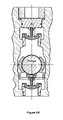
- FIG. 10A schematically illustrates a cross-section of a right-angular plunger pump having outwardly flared transition areas in the suction and discharge bores, a top stem guided suction valve, a discharge valve with top and lower guide stems, and a flangeless access bore plug.
- FIG. 10B schematically illustrates the sectional view labeled B-B in FIG. 10A .
- FIG. 11A schematically illustrates a top view of an SVTSG-SR-II.
- FIG. 11B schematically illustrates the sectional view labeled B-B in FIG. 11A .
- FIG. 11C schematically illustrates the sectional view labeled C-C in FIG. 11A .
- FIG. 12A schematically illustrates a top view of an DVLSG-II.
- FIG. 12B schematically illustrates the sectional view labeled B-B in FIG. 12A .
- FIG. 12C schematically illustrates the sectional view labeled C-C in FIG. 12A .
- FIG. 12D schematically illustrates a bottom view of an DVLSG-II.
- FIG. 13A schematically illustrates a top view of a TDBS.
- FIG. 13B schematically illustrates the sectional view labeled B-B in FIG. 13A .
- FIG. 13C schematically illustrates the sectional view labeled C-C in FIG. 13A .
- FIG. 13D schematically illustrates a bottom view of a TDBS.
- FIG. 14A schematically illustrates an end view of a flangeless access bore plug and separate spacers, each spacer having an insertion ramp.
- FIG. 14B schematically illustrates the sectional view labeled B-B in FIG. 14A .
- FIG. 14C schematically illustrates a top view of the flangeless access bore plug and separate spacers in FIG. 14A .
- FIG. 15A schematically illustrates an end vies of a flanged access bore plug and integral spacers.
- FIG. 15B schematically illustrates the sectional view labeled B-B in FIG. 15A .
- FIG. 15C schematically illustrates a top view of the flanged access bore plug and integral spacers in FIG. 15A .
- FIG. 16A schematically illustrates an end view of a flanged access bore plug and integral spacers, each spacer having an insertion ramp.
- FIG. 16B schematically illustrates the sectional view labeled B-B in FIG. 16A .
- FIG. 16C schematically illustrates a top view of the flanged access bore plug and integral spacers in FIG. 16A .
- FIG. 17A schematically illustrates an end view of a flangeless access bore plug and separate spacers.
- FIG. 17B schematically illustrates the sectional view labeled B-B in FIG. 17A .
- FIG. 17C schematically illustrates a top view of the flangeless access bore plug and separate spacers in FIG. 17A .
- FIG. 7A schematically illustrates cross-sections of a right-angular pump housing 550 of the present invention, including a suction bore 510 having a first centerline and comprising a first portion 512 with substantially circular cross-sections followed a second portion.
- the second portion of suction bore 510 comprises a cylindrical area 518 followed by an outwardly flared transition area 514 .
- a discharge bore 520 comprises a first portion 522 with substantially circular cross-sections, a second portion comprising an outwardly flared transition area 524 , a discharge bore shoulder 526 between the first and second portions, and a second centerline, the first and second centerlines being colinear.
- a plunger bore 530 comprises a proximal packing area 532 having substantially circular cross-sections, a distal transition area 534 , a plunger bore shoulder 536 between packing area 532 and transition area 534 , and a third centerline.
- the third centerline is coplanar with the first and second centerlines.
- an access bore 540 comprises a proximal cylindrical transition area 544 , a distal retainer area 542 with circular cross-sections, a shoulder 546 between transition area 544 and retainer area 542 , and a fourth center line.
- the fourth centerline is colinear with the third center line. Note that each bore transition area in pump housing 550 has at least one adjacent chamfer to provide additional stress relief.
- FIGS. 7B , 7 C, 7 D and 7 E schematically illustrate the indicated partial cross-sections of access bore 540 , discharge bore 520 , plunger bore 530 , and suction bore 510 in FIG. 7A respectively.
- Suction bore outwardly flared transition area 514 and cylindrical area 518 each have at least one elongated cross-section substantially perpendicular to the first centerline and with a long axis substantially perpendicular to a plane containing the first, second, third and fourth centerlines.
- Discharge bore outwardly flared transition area 524 has at least one elongated cross-section substantially perpendicular to the second centerline and with a long axis substantially perpendicular to a plane containing the first, second, third and fourth centerlines.
- Plunger bore transition area 534 has at least one elongated cross-section substantially perpendicular to the third centerline and with a long axis substantially perpendicular to a plane containing the first, second, third and fourth centerlines.
- Access bore transition area 544 has at least one elongated cross-section substantially perpendicular to the fourth centerline and with a long axis substantially perpendicular to a plane containing the first, second, third and fourth centerlines.
- FIGS. 8A-C An embodiment of a valve stem guide and spring retainer assembly within a pump housing 550 is schematically illustrated in FIGS. 8A-C . Components of the assembly are shown in greater detail in FIGS. 11A-C , 13 A-D, and 17 A-C.
- the assembly comprises a tapered discharge bore spacer 650 (see FIGS. 13A-D ) which itself comprises a body 652 having a first end 654 , a second end 656 , a longitudinal axis, and at least one elongated cross-section perpendicular to the longitudinal axis.
- First end 654 comprises a shoulder mating surface 658
- second end 656 comprises at least one discharge lateral alignment lip 660 .
- Body 652 is outwardly flared longitudinally and additionally comprises at least one peripheral O-ring groove 662 , and at least one longitudinal fluid passage 664 extending between first end 654 and second end 656 .
- An O-ring 663 lies in O-ring groove 662 .
- FIGS. 8A-C The embodiment of a valve stem guide and spring retainer assembly within a pump housing 550 as schematically illustrated in FIGS. 8A-C further comprises a tapered suction valve top stem guide and spring retainer 850 (see FIGS. 11A-C ) comprising a body 852 having a first end 854 , a second end 856 , a longitudinal axis, and at least one elongated cross-section perpendicular to the longitudinal axis. Second end 856 comprises at least one suction lateral alignment lip 860 .
- Body 852 is outwardly flared longitudinally and additionally comprises at least one peripheral O-ring groove 862 .
- At least one longitudinal fluid passage 864 extends between first end 854 and second end 856 .
- An O-ring 863 lies in O-ring groove 862 .
- FIGS. 8A-C The embodiment of a valve stem guide and spring retainer assembly within a pump housing 550 as schematically illustrated in FIGS. 8A-C further comprises at least one side spacer 920 (see FIGS. 17A-C ) having first and second parallel edges 922 and 924 respectively for insertion along one discharge lateral alignment lip 660 and an opposing suction lateral alignment lip 860 . Longitudinal movement of each side spacer 920 is limited by flangeless access bore plug 940 and plunger bore shoulder 536 .
- each said side spacer 920 ′ having first and second parallel edges 922 ′ and 924 ′ additionally comprises an insertion ramp 926 on at least one said parallel edge.
- each insertion ramp 926 makes contact with a suction lateral alignment lip or a discharge lateral alignment lip.
- each insertion ramp 926 confers the mechanical advantage of an inclined plane in moving a tapered suction valve top stem guide and spring retainer 850 or a tapered discharge bore spacer 650 further into their respective suction or discharge bores.
- FIGS. 9A-B A first alternative embodiment of a valve stem guide and spring retainer assembly within a pump housing 550 ′ is schematically illustrated in FIGS. 9A-B . Components of the assembly are shown in greater detail in FIGS. 11A-C and 15 A-C. Note that while neither a tapered discharge valve lower stem guide nor a tapered discharge bore spacer is included in this alternative embodiment, a tapered suction valve top stem guide and spring retainer 850 (see FIGS. 11A-C ) is included.
- a side spacer-plug 960 (see FIGS. 15A-C ) comprising a flanged access bore plug 950 integral with at least one side spacer 930 .
- Each side spacer 930 has a first edge 932 for insertion along a suction lateral alignment lip 860 . Longitudinal and lateral movement of each side spacer 930 is limited by flanged access bore plug 950 , with which it is integral.
- a further alternative to the first alternative embodiment comprises a side spacer-plug 960 ′ that is schematically illustrated in FIGS. 16A-C .
- each side spacer 930 ′ has a first edge 932 ′ that additionally comprises an insertion ramp 936 .
- each insertion ramp 936 makes contact with a suction lateral alignment lip. Due to the relatively acute angle (i.e., less than about 45 degrees) that insertion ramp 936 makes with the edge 932 ′, each insertion ramp 936 confers the mechanical advantage of an inclined plane in moving a tapered suction valve top stem guide and spring retainer 850 further into the suction bore.
- FIGS. 10A-B A second alternative embodiment of a valve stem guide and spring retainer assembly within a pump housing 550 is schematically illustrated in FIGS. 10A-B . Components of the assembly are shown in greater detail in FIGS. 11A-C , 12 A-D, and 17 A-C.
- the assembly comprises a tapered discharge valve lower stem guide 750 (see FIGS. 12A-D ) which itself comprises a body 752 having a first end 754 , a second end 756 , a longitudinal axis, and at least one elongated cross-section perpendicular to the longitudinal axis.
- First end 754 comprises a shoulder mating surface 758
- second end 756 comprises at least one discharge lateral alignment lip 760 .
- Body 752 is outwardly flared longitudinally and additionally comprises at least one peripheral O-ring groove 762 , a centrally-located valve stem guide 766 , and at least one longitudinal fluid passage 764 extending between first end 754 and second end 756 .
- An O-ring 763 lies in O-ring groove 762 .
- FIGS. 10A-B The second alternative embodiment of a valve stem guide and spring retainer assembly within a pump housing 550 as schematically illustrated in FIGS. 10A-B further comprises a tapered suction valve top stem guide and spring retainer 850 as described above (see FIGS. 11A-C , and at least one side spacer 920 as described above (see FIGS. 17A-C ).
Landscapes
- Engineering & Computer Science (AREA)
- Mechanical Engineering (AREA)
- General Engineering & Computer Science (AREA)
- Details Of Reciprocating Pumps (AREA)
Abstract
Description
Claims (6)
Priority Applications (4)
| Application Number | Priority Date | Filing Date | Title |
|---|---|---|---|
| US11/125,282 US7513759B1 (en) | 2003-07-03 | 2005-05-09 | Valve guide and spring retainer assemblies |
| US12/390,517 US8147227B1 (en) | 2000-07-18 | 2009-02-23 | Valve guide and spring retainer assemblies |
| US13/430,799 US8894392B1 (en) | 2000-07-18 | 2012-03-27 | Valve guide and spring retainer assemblies |
| US13/899,752 US9416887B2 (en) | 2000-07-18 | 2013-05-22 | Low turbulence valve |
Applications Claiming Priority (2)
| Application Number | Priority Date | Filing Date | Title |
|---|---|---|---|
| US10/613,295 US6910871B1 (en) | 2002-11-06 | 2003-07-03 | Valve guide and spring retainer assemblies |
| US11/125,282 US7513759B1 (en) | 2003-07-03 | 2005-05-09 | Valve guide and spring retainer assemblies |
Related Parent Applications (2)
| Application Number | Title | Priority Date | Filing Date |
|---|---|---|---|
| US10/613,295 Continuation-In-Part US6910871B1 (en) | 2000-07-18 | 2003-07-03 | Valve guide and spring retainer assemblies |
| US10/613,295 Continuation US6910871B1 (en) | 2000-07-18 | 2003-07-03 | Valve guide and spring retainer assemblies |
Related Child Applications (2)
| Application Number | Title | Priority Date | Filing Date |
|---|---|---|---|
| US12/390,517 Continuation-In-Part US8147227B1 (en) | 2000-07-18 | 2009-02-23 | Valve guide and spring retainer assemblies |
| US12/390,517 Continuation US8147227B1 (en) | 2000-07-18 | 2009-02-23 | Valve guide and spring retainer assemblies |
Publications (1)
| Publication Number | Publication Date |
|---|---|
| US7513759B1 true US7513759B1 (en) | 2009-04-07 |
Family
ID=40512671
Family Applications (1)
| Application Number | Title | Priority Date | Filing Date |
|---|---|---|---|
| US11/125,282 Active 2025-05-09 US7513759B1 (en) | 2000-07-18 | 2005-05-09 | Valve guide and spring retainer assemblies |
Country Status (1)
| Country | Link |
|---|---|
| US (1) | US7513759B1 (en) |
Cited By (83)
| Publication number | Priority date | Publication date | Assignee | Title |
|---|---|---|---|---|
| US20090257897A1 (en) * | 2008-04-15 | 2009-10-15 | Maruyama Mfg. Co., Inc. | Reciprocating pump |
| US20110081268A1 (en) * | 2009-08-13 | 2011-04-07 | Brian Ochoa | Pump body |
| US20110189031A1 (en) * | 2010-02-01 | 2011-08-04 | Da Quan Zhang | Method and apparatus for improved, high-pressure, fluid pump |
| US20110189041A1 (en) * | 2010-02-01 | 2011-08-04 | Da Quan Zhang | Method and apparatus for improved, high-pressure, fluid pump |
| US20110255993A1 (en) * | 2010-02-26 | 2011-10-20 | Brian Ochoa | Precompression effect in pump body |
| US8267371B1 (en) | 2011-08-03 | 2012-09-18 | Gilstad Dennis W | Impulse tolerant valve body |
| US8292260B1 (en) | 2011-08-03 | 2012-10-23 | Gilstad Dennis W | Impulse tolerant valve assembly |
| US20120288387A1 (en) * | 2011-04-20 | 2012-11-15 | S.P.M. Flow Control, Inc. | Reciprocating pump with intersecting bore geometry |
| US8496224B1 (en) | 2011-07-18 | 2013-07-30 | Dennis W. Gilstad | Tunable valve assembly |
| US8550102B2 (en) | 2011-01-21 | 2013-10-08 | Fts International Services, Llc | Easily replaceable valve assembly for a high pressure pump |
| US8550425B1 (en) | 2011-09-09 | 2013-10-08 | Dennis W. Gilstad | Impulse tolerant valve assembly |
| US8567753B1 (en) | 2011-07-18 | 2013-10-29 | Dennis W. Gilstad | Tunable valve assembly |
| US8567754B1 (en) | 2011-07-18 | 2013-10-29 | Dennis W. Gilstad | Tunable valve assembly |
| US20140034863A1 (en) * | 2011-07-18 | 2014-02-06 | Dennis W. Gilstad | Tunable Fluid End |
| US8662864B2 (en) | 2010-12-09 | 2014-03-04 | S.P.M. Flow Control, Inc. | Offset valve bore in a reciprocating pump |
| US8708306B2 (en) | 2011-08-03 | 2014-04-29 | Barbara C. Gilstad | Tunable valve assembly |
| USD705817S1 (en) | 2012-06-21 | 2014-05-27 | S.P.M. Flow Control, Inc. | Center portion of a fluid cylinder for a pump |
| USD706397S1 (en) | 2011-08-19 | 2014-06-03 | S.P.M. Flow Control, Inc. | Portion of fluid end |
| USD706833S1 (en) | 2012-04-27 | 2014-06-10 | S.P.M. Flow Control, Inc. | Center portion of a fluid cylinder for a pump |
| USD706832S1 (en) | 2012-06-15 | 2014-06-10 | S.P.M. Flow Control, Inc. | Fluid cylinder for a pump |
| US8746654B2 (en) | 2011-07-18 | 2014-06-10 | Dennis W. Gilstad | Tunable fluid end |
| US8784081B1 (en) * | 2003-09-15 | 2014-07-22 | George H. Blume | Plunger pump fluid end |
| US8827244B2 (en) | 2011-07-18 | 2014-09-09 | Dennis W. Gilstad | Tunable fluid end |
| WO2014135303A1 (en) * | 2013-03-07 | 2014-09-12 | Robert Bosch Gmbh | Pump, in particular fuel pump |
| US20140345452A1 (en) * | 2013-05-21 | 2014-11-27 | Gardner Denver, Inc. | Fluid end having spherical cross-bore intersection |
| US8905376B2 (en) | 2011-07-18 | 2014-12-09 | Dennis W. Gilstad | Tunable check valve |
| US8939200B1 (en) | 2011-07-18 | 2015-01-27 | Dennis W. Gilstad | Tunable hydraulic stimulator |
| US8944409B2 (en) | 2011-07-18 | 2015-02-03 | Dennis W. Gilstad | Tunable fluid end |
| US9027636B2 (en) | 2011-07-18 | 2015-05-12 | Dennis W. Gilstad | Tunable down-hole stimulation system |
| US9080690B2 (en) | 2011-07-18 | 2015-07-14 | Dennis W. Gilstad | Tunable check valve |
| US9169707B1 (en) | 2015-01-22 | 2015-10-27 | Dennis W. Gilstad | Tunable down-hole stimulation array |
| US9188121B1 (en) * | 2014-12-12 | 2015-11-17 | Forum Us, Inc. | Fluid cylinder block having a stress distributing joint |
| US20150361745A1 (en) * | 2013-05-17 | 2015-12-17 | VP Sales and Company | Positive Displacement Pump |
| US20150362113A1 (en) * | 2014-06-11 | 2015-12-17 | Shivrat Chhabra | Systems and methods utilizing a grooveless fluid end for high pressure pumping |
| US9291274B1 (en) | 2001-04-16 | 2016-03-22 | Novatech Holdings Corp. | Valve body and seal assembly |
| US9341179B2 (en) | 2010-02-26 | 2016-05-17 | Schlumberger Technology Corporation | Precompression effect in pump body |
| US9377019B1 (en) | 2012-05-07 | 2016-06-28 | George H Blume | Opposing offset fluid end bores |
| US20160208797A1 (en) * | 2013-09-10 | 2016-07-21 | Serva Group ,LLC | Housing for hi-pressure fluid applications |
| US9732746B2 (en) | 2012-09-24 | 2017-08-15 | Gardner Denver, Inc. | Fluid end of a high pressure plunger pump |
| US9945362B2 (en) | 2012-01-27 | 2018-04-17 | S.P.M. Flow Control, Inc. | Pump fluid end with integrated web portion |
| US20190101109A1 (en) * | 2017-10-02 | 2019-04-04 | S.P.M. Flow Control, Inc. | Valve stop |
| US10337508B2 (en) | 2016-06-17 | 2019-07-02 | Gardner Denver Petroleum Pumps, Llc | Fluid-end of a high pressure pump |
| US10465680B1 (en) | 2018-05-14 | 2019-11-05 | Vp Sales And Company Lp | Discharge cap and block for a fluid end assembly |
| US20200011434A1 (en) * | 2015-09-29 | 2020-01-09 | Kerr Machine Co. | Sealing High Pressure Flow Devices |
| US20200182240A1 (en) * | 2018-12-10 | 2020-06-11 | Kerr Machine Co. | Fluid End |
| US10794381B2 (en) | 2017-04-26 | 2020-10-06 | Gardner Denver Petroleum Pumps, Llc | Reciprocating pump with improved cross-bore |
| WO2020231485A1 (en) * | 2019-05-14 | 2020-11-19 | Halliburton Energy Services, Inc. | Easy change pump plunger |
| US10962001B2 (en) | 2017-07-14 | 2021-03-30 | Kerr Machine Co. | Fluid end assembly |
| USD916240S1 (en) | 2018-12-10 | 2021-04-13 | Kerr Machine Co. | Fluid end |
| US11162479B2 (en) | 2019-11-18 | 2021-11-02 | Kerr Machine Co. | Fluid end |
| US11353117B1 (en) | 2020-01-17 | 2022-06-07 | Vulcan Industrial Holdings, LLC | Valve seat insert system and method |
| US11384756B1 (en) | 2020-08-19 | 2022-07-12 | Vulcan Industrial Holdings, LLC | Composite valve seat system and method |
| US11391374B1 (en) | 2021-01-14 | 2022-07-19 | Vulcan Industrial Holdings, LLC | Dual ring stuffing box |
| US11408419B2 (en) | 2017-07-14 | 2022-08-09 | Kerr Machine Co. | Fluid end assembly |
| US11421679B1 (en) | 2020-06-30 | 2022-08-23 | Vulcan Industrial Holdings, LLC | Packing assembly with threaded sleeve for interaction with an installation tool |
| US11421680B1 (en) | 2020-06-30 | 2022-08-23 | Vulcan Industrial Holdings, LLC | Packing bore wear sleeve retainer system |
| US11434900B1 (en) | 2022-04-25 | 2022-09-06 | Vulcan Industrial Holdings, LLC | Spring controlling valve |
| US11486502B2 (en) | 2015-09-29 | 2022-11-01 | Kerr Machine Co. | Sealing high pressure flow devices |
| US11536378B2 (en) | 2015-09-29 | 2022-12-27 | Kerr Machine Co. | Sealing high pressure flow devices |
| US11536267B2 (en) | 2017-07-14 | 2022-12-27 | Kerr Machine Co. | Fluid end assembly |
| US20220412346A1 (en) * | 2018-12-10 | 2022-12-29 | Kerr Machine Co. | Fluid end |
| US20230003126A1 (en) * | 2016-08-25 | 2023-01-05 | Kerr Machine Co. | Modular gland arrangements for a fluid end assembly |
| US11578711B2 (en) | 2019-11-18 | 2023-02-14 | Kerr Machine Co. | Fluid routing plug |
| US11578710B2 (en) | 2019-05-02 | 2023-02-14 | Kerr Machine Co. | Fracturing pump with in-line fluid end |
| USD980876S1 (en) | 2020-08-21 | 2023-03-14 | Vulcan Industrial Holdings, LLC | Fluid end for a pumping system |
| US11635068B2 (en) | 2019-11-18 | 2023-04-25 | Kerr Machine Co. | Modular power end |
| US11644018B2 (en) | 2019-11-18 | 2023-05-09 | Kerr Machine Co. | Fluid end |
| USD986928S1 (en) | 2020-08-21 | 2023-05-23 | Vulcan Industrial Holdings, LLC | Fluid end for a pumping system |
| US11686296B2 (en) | 2019-11-18 | 2023-06-27 | Kerr Machine Co. | Fluid routing plug |
| US11698063B2 (en) * | 2020-05-15 | 2023-07-11 | American Jereh International Corporation | Hydraulic end assembly structure of a plunger pump |
| US11708830B2 (en) | 2017-12-11 | 2023-07-25 | Kerr Machine Co. | Multi-piece fluid end |
| USD997992S1 (en) | 2020-08-21 | 2023-09-05 | Vulcan Industrial Holdings, LLC | Fluid end for a pumping system |
| US11808364B2 (en) | 2021-11-11 | 2023-11-07 | Kerr Machine Co. | Valve body |
| US11808254B2 (en) | 2019-11-18 | 2023-11-07 | Kerr Machine Co. | Fluid end assembly |
| US11920583B2 (en) | 2021-03-05 | 2024-03-05 | Kerr Machine Co. | Fluid end with clamped retention |
| US11920684B1 (en) | 2022-05-17 | 2024-03-05 | Vulcan Industrial Holdings, LLC | Mechanically or hybrid mounted valve seat |
| US11946465B2 (en) | 2021-08-14 | 2024-04-02 | Kerr Machine Co. | Packing seal assembly |
| US11965503B2 (en) | 2019-05-14 | 2024-04-23 | Halliburton Energy Services, Inc. | Flexible manifold for reciprocating pump |
| US12018759B1 (en) | 2023-02-03 | 2024-06-25 | Gd Energy Products, Llc | Valve seat assembly |
| US12018662B2 (en) | 2019-11-18 | 2024-06-25 | Kerr Machine Co. | High pressure pump |
| USD1034909S1 (en) | 2020-11-18 | 2024-07-09 | Kerr Machine Co. | Crosshead frame |
| US12049889B2 (en) | 2020-06-30 | 2024-07-30 | Vulcan Industrial Holdings, LLC | Packing bore wear sleeve retainer system |
| US12055221B2 (en) | 2021-01-14 | 2024-08-06 | Vulcan Industrial Holdings, LLC | Dual ring stuffing box |
Citations (6)
| Publication number | Priority date | Publication date | Assignee | Title |
|---|---|---|---|---|
| US2257417A (en) * | 1940-04-08 | 1941-09-30 | Frank H Kelley | Power cylinder for internal combustion engines |
| US4084606A (en) * | 1974-04-23 | 1978-04-18 | Baxter Travenol Laboratories, Inc. | Fluid transfer device |
| US4508133A (en) * | 1984-01-31 | 1985-04-02 | Halliburton Company | Protective cover retainer |
| US4771801A (en) * | 1987-02-02 | 1988-09-20 | Halliburton Services | Protective cover assembly with reverse buckling disc |
| US6264441B1 (en) * | 1999-03-16 | 2001-07-24 | Askoll Tre S.P.A. | Pump for the drain outlet of washing machines |
| US20020096217A1 (en) * | 2000-12-05 | 2002-07-25 | Wu Samuel S. | Valve with increased inlet flow |
-
2005
- 2005-05-09 US US11/125,282 patent/US7513759B1/en active Active
Patent Citations (6)
| Publication number | Priority date | Publication date | Assignee | Title |
|---|---|---|---|---|
| US2257417A (en) * | 1940-04-08 | 1941-09-30 | Frank H Kelley | Power cylinder for internal combustion engines |
| US4084606A (en) * | 1974-04-23 | 1978-04-18 | Baxter Travenol Laboratories, Inc. | Fluid transfer device |
| US4508133A (en) * | 1984-01-31 | 1985-04-02 | Halliburton Company | Protective cover retainer |
| US4771801A (en) * | 1987-02-02 | 1988-09-20 | Halliburton Services | Protective cover assembly with reverse buckling disc |
| US6264441B1 (en) * | 1999-03-16 | 2001-07-24 | Askoll Tre S.P.A. | Pump for the drain outlet of washing machines |
| US20020096217A1 (en) * | 2000-12-05 | 2002-07-25 | Wu Samuel S. | Valve with increased inlet flow |
Cited By (130)
| Publication number | Priority date | Publication date | Assignee | Title |
|---|---|---|---|---|
| US9291274B1 (en) | 2001-04-16 | 2016-03-22 | Novatech Holdings Corp. | Valve body and seal assembly |
| US8784081B1 (en) * | 2003-09-15 | 2014-07-22 | George H. Blume | Plunger pump fluid end |
| US20090257897A1 (en) * | 2008-04-15 | 2009-10-15 | Maruyama Mfg. Co., Inc. | Reciprocating pump |
| US20110081268A1 (en) * | 2009-08-13 | 2011-04-07 | Brian Ochoa | Pump body |
| US8601687B2 (en) | 2009-08-13 | 2013-12-10 | Schlumberger Technology Corporation | Pump body |
| US20110189031A1 (en) * | 2010-02-01 | 2011-08-04 | Da Quan Zhang | Method and apparatus for improved, high-pressure, fluid pump |
| US20110189041A1 (en) * | 2010-02-01 | 2011-08-04 | Da Quan Zhang | Method and apparatus for improved, high-pressure, fluid pump |
| US8840383B2 (en) * | 2010-02-01 | 2014-09-23 | Power Plus Products Ltd. | Method and apparatus for improved, high-pressure, fluid pump |
| US20110255993A1 (en) * | 2010-02-26 | 2011-10-20 | Brian Ochoa | Precompression effect in pump body |
| US9341179B2 (en) | 2010-02-26 | 2016-05-17 | Schlumberger Technology Corporation | Precompression effect in pump body |
| US8662865B2 (en) | 2010-12-09 | 2014-03-04 | S.P.M. Flow Control, Inc. | Offset valve bore in a reciprocating pump |
| EP2649315A4 (en) * | 2010-12-09 | 2016-05-11 | Spm Flow Control Inc | Offset valve bore for a reciprocating pump |
| US8662864B2 (en) | 2010-12-09 | 2014-03-04 | S.P.M. Flow Control, Inc. | Offset valve bore in a reciprocating pump |
| US8668470B2 (en) | 2010-12-09 | 2014-03-11 | S.P.M. Flow Control, Inc. | Offset valve bore for a reciprocating pump |
| US9989044B2 (en) | 2010-12-09 | 2018-06-05 | S.P.M. Flow Control, Inc. | Offset valve bore in a reciprocating pump |
| US9784262B2 (en) | 2010-12-09 | 2017-10-10 | S.P.M. Flow Control, Inc. | Offset valve bore in a reciprocating pump |
| EP2649316A4 (en) * | 2010-12-09 | 2015-12-23 | Spm Flow Control Inc | Offset valve bore in a reciprocating pump |
| US8550102B2 (en) | 2011-01-21 | 2013-10-08 | Fts International Services, Llc | Easily replaceable valve assembly for a high pressure pump |
| US20120288387A1 (en) * | 2011-04-20 | 2012-11-15 | S.P.M. Flow Control, Inc. | Reciprocating pump with intersecting bore geometry |
| US8496224B1 (en) | 2011-07-18 | 2013-07-30 | Dennis W. Gilstad | Tunable valve assembly |
| US8567753B1 (en) | 2011-07-18 | 2013-10-29 | Dennis W. Gilstad | Tunable valve assembly |
| US8567754B1 (en) | 2011-07-18 | 2013-10-29 | Dennis W. Gilstad | Tunable valve assembly |
| US8720857B2 (en) * | 2011-07-18 | 2014-05-13 | Dennis W. Gilstad | Tunable fluid end |
| US9080690B2 (en) | 2011-07-18 | 2015-07-14 | Dennis W. Gilstad | Tunable check valve |
| US8746654B2 (en) | 2011-07-18 | 2014-06-10 | Dennis W. Gilstad | Tunable fluid end |
| US8905376B2 (en) | 2011-07-18 | 2014-12-09 | Dennis W. Gilstad | Tunable check valve |
| US8827244B2 (en) | 2011-07-18 | 2014-09-09 | Dennis W. Gilstad | Tunable fluid end |
| US9027636B2 (en) | 2011-07-18 | 2015-05-12 | Dennis W. Gilstad | Tunable down-hole stimulation system |
| US20140034863A1 (en) * | 2011-07-18 | 2014-02-06 | Dennis W. Gilstad | Tunable Fluid End |
| US8944409B2 (en) | 2011-07-18 | 2015-02-03 | Dennis W. Gilstad | Tunable fluid end |
| US8939200B1 (en) | 2011-07-18 | 2015-01-27 | Dennis W. Gilstad | Tunable hydraulic stimulator |
| US8292260B1 (en) | 2011-08-03 | 2012-10-23 | Gilstad Dennis W | Impulse tolerant valve assembly |
| US8267371B1 (en) | 2011-08-03 | 2012-09-18 | Gilstad Dennis W | Impulse tolerant valve body |
| US8708306B2 (en) | 2011-08-03 | 2014-04-29 | Barbara C. Gilstad | Tunable valve assembly |
| USD706397S1 (en) | 2011-08-19 | 2014-06-03 | S.P.M. Flow Control, Inc. | Portion of fluid end |
| US8550425B1 (en) | 2011-09-09 | 2013-10-08 | Dennis W. Gilstad | Impulse tolerant valve assembly |
| US11401930B2 (en) | 2012-01-27 | 2022-08-02 | Spm Oil & Gas Inc. | Method of manufacturing a fluid end block with integrated web portion |
| US10330097B2 (en) | 2012-01-27 | 2019-06-25 | S.P.M. Flow Control, Inc. | Pump fluid end with integrated web portion |
| US9945362B2 (en) | 2012-01-27 | 2018-04-17 | S.P.M. Flow Control, Inc. | Pump fluid end with integrated web portion |
| USD706833S1 (en) | 2012-04-27 | 2014-06-10 | S.P.M. Flow Control, Inc. | Center portion of a fluid cylinder for a pump |
| US9377019B1 (en) | 2012-05-07 | 2016-06-28 | George H Blume | Opposing offset fluid end bores |
| USD706832S1 (en) | 2012-06-15 | 2014-06-10 | S.P.M. Flow Control, Inc. | Fluid cylinder for a pump |
| USD705817S1 (en) | 2012-06-21 | 2014-05-27 | S.P.M. Flow Control, Inc. | Center portion of a fluid cylinder for a pump |
| US9732746B2 (en) | 2012-09-24 | 2017-08-15 | Gardner Denver, Inc. | Fluid end of a high pressure plunger pump |
| WO2014135303A1 (en) * | 2013-03-07 | 2014-09-12 | Robert Bosch Gmbh | Pump, in particular fuel pump |
| US20150361745A1 (en) * | 2013-05-17 | 2015-12-17 | VP Sales and Company | Positive Displacement Pump |
| CN104179675A (en) * | 2013-05-21 | 2014-12-03 | 加德纳丹佛公司 | Fluid end having spherical cross-bore intersection |
| US9383015B2 (en) * | 2013-05-21 | 2016-07-05 | Gardner Denver, Inc. | Fluid end having spherical cross-bore intersection |
| US20140345452A1 (en) * | 2013-05-21 | 2014-11-27 | Gardner Denver, Inc. | Fluid end having spherical cross-bore intersection |
| US20160208797A1 (en) * | 2013-09-10 | 2016-07-21 | Serva Group ,LLC | Housing for hi-pressure fluid applications |
| US9989053B2 (en) * | 2013-09-10 | 2018-06-05 | Serva Group Llc | Housing for high-pressure fluid applications |
| US10683862B2 (en) | 2013-09-10 | 2020-06-16 | Serva Group Llc | Housing for high-pressure fluid applications |
| US20170152851A1 (en) * | 2014-06-11 | 2017-06-01 | Shivrat Chhabra | Systems and methods utilizing a grooveless fluid end for high pressure pumping |
| US9605767B2 (en) * | 2014-06-11 | 2017-03-28 | Strom, Inc. | Systems and methods utilizing a grooveless fluid end for high pressure pumping |
| US10458405B2 (en) * | 2014-06-11 | 2019-10-29 | Strom, Inc. | Systems and methods utilizing a grooveless fluid end for high pressure pumping |
| US20150362113A1 (en) * | 2014-06-11 | 2015-12-17 | Shivrat Chhabra | Systems and methods utilizing a grooveless fluid end for high pressure pumping |
| US9188121B1 (en) * | 2014-12-12 | 2015-11-17 | Forum Us, Inc. | Fluid cylinder block having a stress distributing joint |
| US9297375B1 (en) * | 2014-12-12 | 2016-03-29 | Forum Us, Inc. | Fluid cylinder block having a stress distributing joint |
| US9169707B1 (en) | 2015-01-22 | 2015-10-27 | Dennis W. Gilstad | Tunable down-hole stimulation array |
| US11649900B2 (en) | 2015-09-29 | 2023-05-16 | Kerr Machine Co. | Sealing high pressure flow devices |
| US20200011434A1 (en) * | 2015-09-29 | 2020-01-09 | Kerr Machine Co. | Sealing High Pressure Flow Devices |
| US10591070B2 (en) * | 2015-09-29 | 2020-03-17 | Kerr Machine Co. | Sealing high pressure flow devices |
| US11649901B2 (en) | 2015-09-29 | 2023-05-16 | Kerr Machine Co. | Sealing high pressure flow devices |
| US10895325B2 (en) * | 2015-09-29 | 2021-01-19 | Kerr Machine Co. | Sealing high pressure flow devices |
| US10907738B2 (en) | 2015-09-29 | 2021-02-02 | Kerr Machine Co. | Sealing high pressure flow devices |
| US11536378B2 (en) | 2015-09-29 | 2022-12-27 | Kerr Machine Co. | Sealing high pressure flow devices |
| US11486502B2 (en) | 2015-09-29 | 2022-11-01 | Kerr Machine Co. | Sealing high pressure flow devices |
| US11143315B2 (en) | 2015-09-29 | 2021-10-12 | Kerr Machine Co. | Sealing high pressure flow devices |
| US10337508B2 (en) | 2016-06-17 | 2019-07-02 | Gardner Denver Petroleum Pumps, Llc | Fluid-end of a high pressure pump |
| US12000285B2 (en) * | 2016-08-25 | 2024-06-04 | Kerr Machine Co. | Modular gland arrangements for a fluid end assembly |
| US20230003126A1 (en) * | 2016-08-25 | 2023-01-05 | Kerr Machine Co. | Modular gland arrangements for a fluid end assembly |
| US10794381B2 (en) | 2017-04-26 | 2020-10-06 | Gardner Denver Petroleum Pumps, Llc | Reciprocating pump with improved cross-bore |
| US10962001B2 (en) | 2017-07-14 | 2021-03-30 | Kerr Machine Co. | Fluid end assembly |
| US11408419B2 (en) | 2017-07-14 | 2022-08-09 | Kerr Machine Co. | Fluid end assembly |
| US11655812B2 (en) | 2017-07-14 | 2023-05-23 | Kerr Machine Co. | Fluid end assembly |
| US11536267B2 (en) | 2017-07-14 | 2022-12-27 | Kerr Machine Co. | Fluid end assembly |
| US20190101109A1 (en) * | 2017-10-02 | 2019-04-04 | S.P.M. Flow Control, Inc. | Valve stop |
| US11708830B2 (en) | 2017-12-11 | 2023-07-25 | Kerr Machine Co. | Multi-piece fluid end |
| US10465680B1 (en) | 2018-05-14 | 2019-11-05 | Vp Sales And Company Lp | Discharge cap and block for a fluid end assembly |
| US10941765B2 (en) * | 2018-12-10 | 2021-03-09 | Kerr Machine Co. | Fluid end |
| US20240035468A1 (en) * | 2018-12-10 | 2024-02-01 | Kerr Machine Co. | Fluid end |
| US11788527B2 (en) * | 2018-12-10 | 2023-10-17 | Kerr Machine Co. | Fluid end |
| USD928917S1 (en) | 2018-12-10 | 2021-08-24 | Kerr Machine Co. | Fluid end |
| US20220412346A1 (en) * | 2018-12-10 | 2022-12-29 | Kerr Machine Co. | Fluid end |
| USD916240S1 (en) | 2018-12-10 | 2021-04-13 | Kerr Machine Co. | Fluid end |
| US11434901B2 (en) | 2018-12-10 | 2022-09-06 | Kerr Machine Co. | Fluid end |
| US20200182240A1 (en) * | 2018-12-10 | 2020-06-11 | Kerr Machine Co. | Fluid End |
| USD989916S1 (en) | 2018-12-10 | 2023-06-20 | Kerr Machine Co. | Fluid end |
| USD1012241S1 (en) | 2018-12-10 | 2024-01-23 | Kerr Machine Co. | Fluid end |
| US11578710B2 (en) | 2019-05-02 | 2023-02-14 | Kerr Machine Co. | Fracturing pump with in-line fluid end |
| US11592011B2 (en) | 2019-05-02 | 2023-02-28 | Kerr Machine Co. | Fracturing pump with in-line fluid end |
| US11952986B2 (en) | 2019-05-02 | 2024-04-09 | Kerr Machine Co. | Fracturing pump arrangement using a plunger with an internal fluid passage |
| WO2020231485A1 (en) * | 2019-05-14 | 2020-11-19 | Halliburton Energy Services, Inc. | Easy change pump plunger |
| US11965503B2 (en) | 2019-05-14 | 2024-04-23 | Halliburton Energy Services, Inc. | Flexible manifold for reciprocating pump |
| US11560888B2 (en) | 2019-05-14 | 2023-01-24 | Halliburton Energy Services, Inc. | Easy change pump plunger |
| US11635068B2 (en) | 2019-11-18 | 2023-04-25 | Kerr Machine Co. | Modular power end |
| US11346339B2 (en) | 2019-11-18 | 2022-05-31 | Kerr Machine Co. | High pressure pump |
| US11162479B2 (en) | 2019-11-18 | 2021-11-02 | Kerr Machine Co. | Fluid end |
| US11635151B2 (en) | 2019-11-18 | 2023-04-25 | Kerr Machine Co | Modular power end |
| US11560884B2 (en) | 2019-11-18 | 2023-01-24 | Kerr Machine Co. | Fluid end |
| US11644018B2 (en) | 2019-11-18 | 2023-05-09 | Kerr Machine Co. | Fluid end |
| US11208996B2 (en) | 2019-11-18 | 2021-12-28 | Kerr Machine Co. | Modular power end |
| US11300111B2 (en) | 2019-11-18 | 2022-04-12 | Kerr Machine Co. | Fluid routing plug |
| US12018662B2 (en) | 2019-11-18 | 2024-06-25 | Kerr Machine Co. | High pressure pump |
| US11808254B2 (en) | 2019-11-18 | 2023-11-07 | Kerr Machine Co. | Fluid end assembly |
| US11578711B2 (en) | 2019-11-18 | 2023-02-14 | Kerr Machine Co. | Fluid routing plug |
| US11686296B2 (en) | 2019-11-18 | 2023-06-27 | Kerr Machine Co. | Fluid routing plug |
| US11359615B2 (en) | 2019-11-18 | 2022-06-14 | Kerr Machine Co. | Fluid end |
| US11846282B2 (en) | 2019-11-18 | 2023-12-19 | Kerr Machine Co. | High pressure pump |
| US11859611B2 (en) | 2019-11-18 | 2024-01-02 | Kerr Machine Co. | Fluid routing plug |
| US11353117B1 (en) | 2020-01-17 | 2022-06-07 | Vulcan Industrial Holdings, LLC | Valve seat insert system and method |
| US11698063B2 (en) * | 2020-05-15 | 2023-07-11 | American Jereh International Corporation | Hydraulic end assembly structure of a plunger pump |
| US20240035462A1 (en) * | 2020-05-15 | 2024-02-01 | American Jereh International Corporation | Hydraulic end assembly structure of a plunger pump |
| US11421679B1 (en) | 2020-06-30 | 2022-08-23 | Vulcan Industrial Holdings, LLC | Packing assembly with threaded sleeve for interaction with an installation tool |
| US12049889B2 (en) | 2020-06-30 | 2024-07-30 | Vulcan Industrial Holdings, LLC | Packing bore wear sleeve retainer system |
| US11421680B1 (en) | 2020-06-30 | 2022-08-23 | Vulcan Industrial Holdings, LLC | Packing bore wear sleeve retainer system |
| US11384756B1 (en) | 2020-08-19 | 2022-07-12 | Vulcan Industrial Holdings, LLC | Composite valve seat system and method |
| USD997992S1 (en) | 2020-08-21 | 2023-09-05 | Vulcan Industrial Holdings, LLC | Fluid end for a pumping system |
| USD986928S1 (en) | 2020-08-21 | 2023-05-23 | Vulcan Industrial Holdings, LLC | Fluid end for a pumping system |
| USD980876S1 (en) | 2020-08-21 | 2023-03-14 | Vulcan Industrial Holdings, LLC | Fluid end for a pumping system |
| USD1034909S1 (en) | 2020-11-18 | 2024-07-09 | Kerr Machine Co. | Crosshead frame |
| US11391374B1 (en) | 2021-01-14 | 2022-07-19 | Vulcan Industrial Holdings, LLC | Dual ring stuffing box |
| US12055221B2 (en) | 2021-01-14 | 2024-08-06 | Vulcan Industrial Holdings, LLC | Dual ring stuffing box |
| US11920583B2 (en) | 2021-03-05 | 2024-03-05 | Kerr Machine Co. | Fluid end with clamped retention |
| US11946465B2 (en) | 2021-08-14 | 2024-04-02 | Kerr Machine Co. | Packing seal assembly |
| US11808364B2 (en) | 2021-11-11 | 2023-11-07 | Kerr Machine Co. | Valve body |
| US11761441B1 (en) * | 2022-04-25 | 2023-09-19 | Vulcan Industrial Holdings, LLC | Spring controlling valve |
| US11434900B1 (en) | 2022-04-25 | 2022-09-06 | Vulcan Industrial Holdings, LLC | Spring controlling valve |
| US11920684B1 (en) | 2022-05-17 | 2024-03-05 | Vulcan Industrial Holdings, LLC | Mechanically or hybrid mounted valve seat |
| US12018759B1 (en) | 2023-02-03 | 2024-06-25 | Gd Energy Products, Llc | Valve seat assembly |
Similar Documents
| Publication | Publication Date | Title |
|---|---|---|
| US7513759B1 (en) | Valve guide and spring retainer assemblies | |
| US8894392B1 (en) | Valve guide and spring retainer assemblies | |
| US6910871B1 (en) | Valve guide and spring retainer assemblies | |
| US9377019B1 (en) | Opposing offset fluid end bores | |
| US8784081B1 (en) | Plunger pump fluid end | |
| US8915722B1 (en) | Integrated fluid end | |
| US10527036B2 (en) | Pump housing with inline valve | |
| US20220349399A1 (en) | Fluid end plug with bore clearance | |
| US6382940B1 (en) | High pressure plunger pump housing and packing | |
| US20180058444A1 (en) | Pump housing with multiple discharge valves | |
| US9695812B2 (en) | Reciprocating pump assembly | |
| US7152622B2 (en) | Check valve | |
| US9284953B2 (en) | Multiple port discharge manifold fluid end | |
| US7364412B2 (en) | System, method, and apparatus for valve stop assembly in a reciprocating pump | |
| CN112922827A (en) | Valve spring seat sleeve, valve component and plunger pump | |
| US4264054A (en) | Metal-to-metal seat hub seals | |
| CA2344283A1 (en) | Multi-valve injection/aspiration manifold | |
| GB2377743A (en) | Spring biassed seal segments in plug valve | |
| US6412783B1 (en) | Self aligning stuffing box for pumpjacks | |
| US20060272804A1 (en) | Self-aligning stuffing box | |
| US20140334947A1 (en) | Fluid pump system | |
| US5037064A (en) | Gate valves | |
| US8499783B2 (en) | Gate valve with seals | |
| US6755629B2 (en) | Fuel injection pump having one-way valve for supplying fuel into pressurizing chamber | |
| EP1096180B1 (en) | Seal arrangement |
Legal Events
| Date | Code | Title | Description |
|---|---|---|---|
| STCF | Information on status: patent grant |
Free format text: PATENTED CASE |
|
| REMI | Maintenance fee reminder mailed | ||
| FPAY | Fee payment |
Year of fee payment: 4 |
|
| SULP | Surcharge for late payment | ||
| FPAY | Fee payment |
Year of fee payment: 8 |
|
| FEPP | Fee payment procedure |
Free format text: MAINTENANCE FEE REMINDER MAILED (ORIGINAL EVENT CODE: REM.); ENTITY STATUS OF PATENT OWNER: SMALL ENTITY |
|
| FEPP | Fee payment procedure |
Free format text: 11.5 YR SURCHARGE- LATE PMT W/IN 6 MO, SMALL ENTITY (ORIGINAL EVENT CODE: M2556); ENTITY STATUS OF PATENT OWNER: SMALL ENTITY |
|
| MAFP | Maintenance fee payment |
Free format text: PAYMENT OF MAINTENANCE FEE, 12TH YR, SMALL ENTITY (ORIGINAL EVENT CODE: M2553); ENTITY STATUS OF PATENT OWNER: SMALL ENTITY Year of fee payment: 12 |
|
| AS | Assignment |
Owner name: ALTIS INVESTMENTS, LLC, TEXAS Free format text: ASSIGNMENT OF ASSIGNORS INTEREST;ASSIGNOR:BLUME, ALICE FAYE;REEL/FRAME:056124/0033 Effective date: 20210502 Owner name: BLUME, ALICE FAYE, TEXAS Free format text: ASSIGNMENT OF ASSIGNORS INTEREST;ASSIGNOR:ESTATE OF GEORGE H. BLUME, JR.;REEL/FRAME:056123/0850 Effective date: 20210502 |
|
| AS | Assignment |
Owner name: VULCAN INDUSTRIAL HOLDINGS, LLC, TEXAS Free format text: ASSIGNMENT OF ASSIGNORS INTEREST;ASSIGNOR:ALTIS INVESTMENTS, LLC;REEL/FRAME:068467/0228 Effective date: 20240830 |