US7510239B2 - Air-conditioning device for the passenger area of a vehicle - Google Patents
Air-conditioning device for the passenger area of a vehicle Download PDFInfo
- Publication number
- US7510239B2 US7510239B2 US10/549,467 US54946704A US7510239B2 US 7510239 B2 US7510239 B2 US 7510239B2 US 54946704 A US54946704 A US 54946704A US 7510239 B2 US7510239 B2 US 7510239B2
- Authority
- US
- United States
- Prior art keywords
- layer
- cushion core
- air distribution
- intermediate layer
- air
- Prior art date
- Legal status (The legal status is an assumption and is not a legal conclusion. Google has not performed a legal analysis and makes no representation as to the accuracy of the status listed.)
- Expired - Fee Related, expires
Links
- 238000004378 air conditioning Methods 0.000 title 1
- 238000009826 distribution Methods 0.000 claims abstract description 77
- 239000011796 hollow space material Substances 0.000 claims abstract description 17
- 238000010438 heat treatment Methods 0.000 claims description 81
- 239000004020 conductor Substances 0.000 claims description 60
- 239000000463 material Substances 0.000 claims description 22
- 239000000853 adhesive Substances 0.000 claims description 13
- 230000001070 adhesive effect Effects 0.000 claims description 13
- 230000007704 transition Effects 0.000 claims description 3
- 230000005540 biological transmission Effects 0.000 claims description 2
- 239000010410 layer Substances 0.000 description 238
- 239000003570 air Substances 0.000 description 96
- 239000006260 foam Substances 0.000 description 39
- 239000004753 textile Substances 0.000 description 18
- 125000006850 spacer group Chemical group 0.000 description 17
- 230000006870 function Effects 0.000 description 14
- 239000010408 film Substances 0.000 description 9
- OKTJSMMVPCPJKN-UHFFFAOYSA-N Carbon Chemical compound [C] OKTJSMMVPCPJKN-UHFFFAOYSA-N 0.000 description 8
- 230000000694 effects Effects 0.000 description 8
- 239000013518 molded foam Substances 0.000 description 7
- 238000004873 anchoring Methods 0.000 description 6
- 239000004744 fabric Substances 0.000 description 6
- 239000008187 granular material Substances 0.000 description 6
- 238000004519 manufacturing process Methods 0.000 description 6
- XLYOFNOQVPJJNP-UHFFFAOYSA-N water Chemical compound O XLYOFNOQVPJJNP-UHFFFAOYSA-N 0.000 description 6
- 239000000945 filler Substances 0.000 description 5
- 238000010097 foam moulding Methods 0.000 description 5
- 210000004209 hair Anatomy 0.000 description 5
- 239000002131 composite material Substances 0.000 description 4
- 238000005485 electric heating Methods 0.000 description 4
- 239000004033 plastic Substances 0.000 description 4
- 229920003023 plastic Polymers 0.000 description 4
- 230000005855 radiation Effects 0.000 description 4
- 238000011084 recovery Methods 0.000 description 4
- 239000004065 semiconductor Substances 0.000 description 4
- 229920001169 thermoplastic Polymers 0.000 description 4
- 239000004416 thermosoftening plastic Substances 0.000 description 4
- 238000009423 ventilation Methods 0.000 description 4
- 239000011248 coating agent Substances 0.000 description 3
- 238000000576 coating method Methods 0.000 description 3
- 238000009434 installation Methods 0.000 description 3
- 239000007788 liquid Substances 0.000 description 3
- 230000007246 mechanism Effects 0.000 description 3
- 238000000034 method Methods 0.000 description 3
- 230000004044 response Effects 0.000 description 3
- 229920000049 Carbon (fiber) Polymers 0.000 description 2
- 239000004793 Polystyrene Substances 0.000 description 2
- 229920005830 Polyurethane Foam Polymers 0.000 description 2
- 230000002411 adverse Effects 0.000 description 2
- JRPBQTZRNDNNOP-UHFFFAOYSA-N barium titanate Chemical compound [Ba+2].[Ba+2].[O-][Ti]([O-])([O-])[O-] JRPBQTZRNDNNOP-UHFFFAOYSA-N 0.000 description 2
- 229910002113 barium titanate Inorganic materials 0.000 description 2
- 238000005452 bending Methods 0.000 description 2
- 239000004917 carbon fiber Substances 0.000 description 2
- 239000000919 ceramic Substances 0.000 description 2
- 230000006835 compression Effects 0.000 description 2
- 238000007906 compression Methods 0.000 description 2
- 238000010276 construction Methods 0.000 description 2
- 238000001816 cooling Methods 0.000 description 2
- 230000008878 coupling Effects 0.000 description 2
- 238000010168 coupling process Methods 0.000 description 2
- 238000005859 coupling reaction Methods 0.000 description 2
- 238000007791 dehumidification Methods 0.000 description 2
- 229920001971 elastomer Polymers 0.000 description 2
- 238000004049 embossing Methods 0.000 description 2
- 239000000835 fiber Substances 0.000 description 2
- 239000012530 fluid Substances 0.000 description 2
- JEGUKCSWCFPDGT-UHFFFAOYSA-N h2o hydrate Chemical compound O.O JEGUKCSWCFPDGT-UHFFFAOYSA-N 0.000 description 2
- 239000008258 liquid foam Substances 0.000 description 2
- 238000002844 melting Methods 0.000 description 2
- 230000008018 melting Effects 0.000 description 2
- 238000003801 milling Methods 0.000 description 2
- 230000035515 penetration Effects 0.000 description 2
- 229920002223 polystyrene Polymers 0.000 description 2
- 239000011496 polyurethane foam Substances 0.000 description 2
- 239000000843 powder Substances 0.000 description 2
- 230000008569 process Effects 0.000 description 2
- 238000004080 punching Methods 0.000 description 2
- 230000007480 spreading Effects 0.000 description 2
- 238000003892 spreading Methods 0.000 description 2
- 239000012815 thermoplastic material Substances 0.000 description 2
- 206010016334 Feeling hot Diseases 0.000 description 1
- 229920006328 Styrofoam Polymers 0.000 description 1
- 238000005299 abrasion Methods 0.000 description 1
- 239000006096 absorbing agent Substances 0.000 description 1
- 239000011358 absorbing material Substances 0.000 description 1
- 230000001133 acceleration Effects 0.000 description 1
- 230000009471 action Effects 0.000 description 1
- 239000012790 adhesive layer Substances 0.000 description 1
- 239000012080 ambient air Substances 0.000 description 1
- 230000009286 beneficial effect Effects 0.000 description 1
- 238000007664 blowing Methods 0.000 description 1
- 210000000078 claw Anatomy 0.000 description 1
- 239000002826 coolant Substances 0.000 description 1
- 230000003111 delayed effect Effects 0.000 description 1
- 238000001514 detection method Methods 0.000 description 1
- 238000010410 dusting Methods 0.000 description 1
- 238000005286 illumination Methods 0.000 description 1
- 239000011810 insulating material Substances 0.000 description 1
- 238000005304 joining Methods 0.000 description 1
- 210000003127 knee Anatomy 0.000 description 1
- 238000009940 knitting Methods 0.000 description 1
- 238000010030 laminating Methods 0.000 description 1
- 238000002156 mixing Methods 0.000 description 1
- 239000000203 mixture Substances 0.000 description 1
- 239000004745 nonwoven fabric Substances 0.000 description 1
- 230000003287 optical effect Effects 0.000 description 1
- 230000008447 perception Effects 0.000 description 1
- 230000035699 permeability Effects 0.000 description 1
- 229920002635 polyurethane Polymers 0.000 description 1
- 239000004814 polyurethane Substances 0.000 description 1
- 238000003825 pressing Methods 0.000 description 1
- 238000009877 rendering Methods 0.000 description 1
- 230000000284 resting effect Effects 0.000 description 1
- 238000009958 sewing Methods 0.000 description 1
- 239000008261 styrofoam Substances 0.000 description 1
- 238000006467 substitution reaction Methods 0.000 description 1
- 230000035900 sweating Effects 0.000 description 1
- 230000000007 visual effect Effects 0.000 description 1
- 239000002699 waste material Substances 0.000 description 1
- 238000004804 winding Methods 0.000 description 1
- 210000002268 wool Anatomy 0.000 description 1
Images


Classifications
-
- B—PERFORMING OPERATIONS; TRANSPORTING
- B60—VEHICLES IN GENERAL
- B60N—SEATS SPECIALLY ADAPTED FOR VEHICLES; VEHICLE PASSENGER ACCOMMODATION NOT OTHERWISE PROVIDED FOR
- B60N2/00—Seats specially adapted for vehicles; Arrangement or mounting of seats in vehicles
- B60N2/56—Heating or ventilating devices
- B60N2/5607—Heating or ventilating devices characterised by convection
- B60N2/5621—Heating or ventilating devices characterised by convection by air
- B60N2/5635—Heating or ventilating devices characterised by convection by air coming from the passenger compartment
-
- B—PERFORMING OPERATIONS; TRANSPORTING
- B60—VEHICLES IN GENERAL
- B60N—SEATS SPECIALLY ADAPTED FOR VEHICLES; VEHICLE PASSENGER ACCOMMODATION NOT OTHERWISE PROVIDED FOR
- B60N2/00—Seats specially adapted for vehicles; Arrangement or mounting of seats in vehicles
- B60N2/56—Heating or ventilating devices
- B60N2/5607—Heating or ventilating devices characterised by convection
- B60N2/5621—Heating or ventilating devices characterised by convection by air
- B60N2/5657—Heating or ventilating devices characterised by convection by air blown towards the seat surface
Definitions
- the present invention concerns a device for climate control of a motor vehicle seat according vehicle seat.
- a device for climate control of a motor vehicle seat with a cushion core for supporting a passenger having an upper air distribution device at a front side of the cushion core facing the passenger to distribute air along the front side of the cushion core, and having a lower air distribution device at its rear side facing away from the passenger to distribute air along the rear side of the cushion core, and a connecting device for transferring air between the first and second air distribution devices.
- U.S. Pat. No. 2,992,604 is a seat cushion that can be separated from the seat in which air is moved by a fan and blown into a coil pad resting on the seat. In colder weather, especially in winter, however, such cushions must be removed to make it possible to activate an existing seat heater. Otherwise the seat cushion would screen the passenger from the heat produced by the seat heater to an excessive degree, thus rendering the heater largely ineffective.
- the present invention provides a device for climate control of a motor vehicle seat with a cushion core for supporting a passenger, having an upper air distribution device at a front side of the cushion core facing the passenger to distribute air along the front side of the cushion core, and having a lower air distribution device at its rear side facing away from the passenger to distribute air along the rear side of the cushion core, and a connecting device for transferring air between the first and second air distribution devices.
- Each of the first and second air distribution devices and the connecting device has an elongated hollow space.
- at least one support element in the form a spiral spring is provided in the air-conducting cross-section of at least one of the hollow spaces.
- a device provides an upper air distribution device front side of a cushion core facing a passenger in order to distribute air along the front side of the cushion core. Moreover, a corresponding lower air distribution device is provided at the rear side of the cushion core facing away from the passenger. In addition, a connecting device is provided to transfer air between the first and second air distribution devices.
- Each of the three devices has an elongated hollow space. Further, at least one support element in the form of a spiral spring is provided in the air-conducting cross-section of at least one such hollow space.
- An advantageous embodiment of the invention can provide the device with air distribution devices or layers.
- an upper air distribution device can be provided at a front side of a cushion core facing a passenger and a lower air distribution device can be provided at a rear side of the cushion core facing away from the passenger.
- a connecting device to transfer air between the first and second air distribution layers can be present, for example in the form of an air duct or in the form of multiple air ducts.
- At least one of the three said devices (upper and lower air distribution devices, connecting device) can have an elongated hollow space. This elongated hollow space is preferably formed at least partly from parts of the intermediate layer.
- at least one support element is provided in the air-conducting cross-section of the hollow space.
- the functional element can be a conducting device, in particular an optical waveguide, a flat cable, a round cable, a heating conductor, a pneumatic line or a fluid-carrying hose. Possible fluids include, for example, coolant and the like.
- the functional element can optionally also be an actuating device, for example a massage device, an operating element, an adjustment device or a thermostat.
- the functional element can optionally also be a passive non-electrical device, particularly a shaped or free-form filler.
- the filler can in particular have heat-insulating materials such as polystyrene or moisture-absorbing materials such as activated carbon.
- the filler can in particular have textile or textile-like components such as wool, natural fibers, recycled foam waste and/or rubberized hair, and in particular can have a flocked or granular form or the like.
- the support element can have a spring, in particular preferably a spring coiled in a spiral or meandering shape, which can in particular comprise or be made from a band-shaped plastic material. Provision can be made that the support element 14 is made of a firm but flexible material.
- the support element preferably includes multiple springs on a supporting layer that carries them, a spacer textile with a large air volume that is kept open, a foam with a surface structure that in particular has a napped profile and/or a rubberized hair mat with bristles or made from or with, for example, a nonwoven material.
- the support element can additionally have a moisture-storing surface, in particular through dusting or coating with activated carbon or the like.
- the device is connected to at least one ventilating device that serves to convey air through the intermediate layer.
- the transfer of air from the ventilating unit into the device according to the invention can, in particular, be perpendicular to or flush with the intermediate layer.
- the transfer of air preferably takes place into a region of the intermediate layer having increased layer thickness.
- it is preferred that the transfer of air takes place into a region of the intermediate layer which has a thickened, round cross-section at one end and preferably has a fiat widened cross-section at the other end.
- the ventilating device can, in particular, be connected to the front side of the cushion core facing the passenger. However, if desired, the ventilating device can also be connected at the rear side of the cushion core facing away from the passenger.
- the connecting device can preferably have at least one recess in the cushion core, which in particular can be arranged vertically.
- the recess in the cushion core is preferably connected to the intermediate layer of the upper air distribution device and/or the intermediate layer of the lower air distribution device, in such a manner as to permit the passage of air.
- a textile layer in particular, can be considered for the base layer.
- This textile layer of the base layer can in particular have a nonwoven mat, a foam and/or a film.
- the base layer is preferably thick enough to prevent support elements and/or functional elements from showing through.
- the base layer can at least in part be translucent or transparent.
- the base layer is impermeable to water vapor and water-resistant.
- the base layer can, for example, be composed of the cushion core of the motor vehicle seat, a region of the intermediate layer that has increased density, a seat cover, and/or a planar heating element.
- a textile layer in particular, can also be considered for the cover layer.
- This textile layer of the cover layer can in particular have a nonwoven mat, a foam and/or a film.
- the cover layer is preferably thick enough to prevent support elements and/or functional elements from showing through.
- the cover layer can at least in part be translucent or transparent.
- the cover layer can, for example, be composed of the cushion core of the motor vehicle seat, a region of the intermediate layer that has increased density, a seat cover, and/or a planar heating element.
- the base layer is joined to the cushion core in a material-to-material fashion.
- the inventive device can in particular be joined to the cushion core by foam molding during the manufacture thereof.
- the intermediate layer and/or the base layer can in particular have a layer that is essentially impermeable to liquids and is arranged on the side of the intermediate layer facing the cushion core, said intermediate layer preferably consisting of the same material as the cushion core.
- Polyurethane in particular comes into consideration as a material for this layer and the cushion core.
- the liquid-impermeable layer can essentially constitute the base layer.
- the inventive device and/or parts thereof can be placed in recesses in the cushion core and can be fastened there, for example, by adhesive joins, hooks, hook-and-loop fasteners, or similar means.
- planar electric heating element is arranged on or in the intermediate layer, the base layer, and/or the cover layer.
- the heating element can constitute one of these three said layers.
- the planar electric heating element can preferably have an electrically heatable textile that is preferably arranged on the side of the intermediate layer facing the passenger.
- the electrically heatable textile material of the heating element can, in particular, have carbon fibers and/or an electrically conductive film and/or at least one stranded heating wire laid or arranged in a meandering shape.
- a conductor in particular a heating conductor, can be provided which is arranged in particular in at least one intermediate space between at least two support elements in the intermediate layer, or, in particular, is arranged in an intermediate space formed by a support element in the intermediate layer.
- the cushion core likewise has at least one support element.
- the cushion core can in particular be composed essentially of a plurality of support elements.
- Switching on of the heating element and/or of the heating conductor can cause air to flow along and in the intermediate layer.
- Such an airflow in the intermediate layer can also be induced by other means of heating the seat, in particular by solar radiation or by a passenger located on the seat.
- FIG. 1 shows a schematic, perspective view of a cushion core
- FIG. 2 shows another schematic, perspective view of a cushion core
- FIG. 3 shows a schematic, perspective view to illustrate various variants of a base layer
- FIG. 4 shows a schematic, perspective view of a cushion of a motor vehicle seat
- FIG. 5 shows a cross-sectional view of the motor vehicle seat from FIG. 4 .
- FIG. 6 shows a cross-sectional view of a first structural variant of the cushion core
- FIG. 7 shows a cross-sectional view of an alternative structural variant of the cushion core
- FIG. 8 shows a cross-sectional view of another structural variant of the cushion core
- FIG. 9 shows a perspective view of a first embodiment of a support element
- FIG. 10 shows a perspective view of another embodiment of a support element
- FIG. 11 shows a schematic view of a supporting layer with incorporated support elements
- FIG. 12 shows a structural variant of an intermediate layer with recessed and raised surface regions
- FIG. 13 shows a design for a cover layer with surface structure applied thereto
- FIG. 15 shows an alternative variant of a ventilating device joined to the intermediate layer
- FIG. 16 shows a schematic representation illustrating an air duct
- FIG. 17 shows another representation of a motor vehicle seat with heating element applied to its upper side
- FIGS. show 18 - 21 various representations of coupling the ventilating device to the intermediate layer
- FIGS. show 22 and 23 alternative structural variations of the base layer with support elements or conductive elements applied thereto
- FIG. 24 shows a schematic cross-sectional representation to illustrate an alternative for coupling the ventilating device to the intermediate layer
- FIG. 25 shows a schematic cross-sectional representation of a motor vehicle seat with an inventive device.
- FIG. 26 shows another embodiment of the invention in perspective view
- FIG. 27 shows electrical equivalent schematic of the arrangement from FIG. 26 .
- FIG. 28 shows cross-section through a seat with an arrangement from FIG. 26 .
- FIG. 29 shows longitudinal section through a seat with details of attachment of the ventilating device
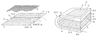
- FIG. 1 shows the basic structure of a device according to the invention in schematic, perspective view, using the example of a cushion.
- the cushion shown as the composite component comprises a bottom cushion core 22 and a base layer 8 placed thereon and joined to the cushion core, which base layer is preferably designed as a layer 76 that is impermeable to liquids.
- Located on the relatively thin base layer 8 is an intermediate layer 10 that is applied thereto and covered with a cover layer 12 .
- the same situation, but without the cover layer 12 is shown once again in FIG. 2 .
- the cushion core 22 can be made, for example, of polyurethane foam (resilient polyurethane foam) or, for example, of rubberized hair.
- the intermediate layer 10 that functions as a distribution layer is composed of a spacer material which is characterized by high air permeability both transverse and perpendicular to the component surface. Air can flow through the intermediate layer 10 as illustrated in the following figures.
- the schematic perspective view in FIG. 3 shows different design possibilities for the base layer 8 , which can have multiple strips arranged adjacent to one another.
- the intermediate layer 10 Located above the base layer 8 is the intermediate layer 10 .
- a first strip has functional elements 18 , which can take the form of fillers 48 , for example.
- a second strip adjacent thereto encompasses a support element 14 incorporated therein, which can take the form, for example, of a coil spring or the like.
- a functional element 18 in the form of a sensor 40 and/or an actuator 46 can be applied to this center section of the base layer 8 .
- the sensor 40 can be embodied as a temperature sensor, for example.
- the third strip has a conducting device 42 in the form of a heating wire or the like, as well as a support element 14 extending in a meandering shape.
- the cover layer 12 over this is merely indicated.
- the functional elements 18 can be arranged in the space between the se layer 8 , the cover layer 12 and the support element 14 .
- FIG. 4 illustrates one possible construction of a vehicle seat 20 .
- This seat has an interior cushion core 22 , which is covered by a U-shaped base layer 8 .
- the base layer 8 embodied as a liquid-impermeable layer 76 , encloses the cushion core 22 on the latter's top, end face and underside.
- An intermediate layer 10 running along the base layer 8 has a functional element 18 in the form of a conducting device 42 , which functions as an electrical connecting line to a planar heating element 74 , which is located on the cover layer 12 .
- the region of the intermediate layer 10 on the top/front side 27 of the cushion core 22 functions as a hollow space 37 and/or as an upper air distribution device 25 .
- the region of the intermediate layer 10 on the rear side 30 of the cushion core 22 likewise forms a hollow space 37 and functions as a lower air distribution device 32 .
- the front region of the intermediate layer 10 at the face of the cushion core 22 forms a hollow space 37 , which functions as a connecting device 35 between the upper air distribution device 25 and the lower air distribution device 32 .
- FIGS. 5 to 8 illustrate various alternative possibilities for transport of air from the cushion lower side to the cushion upper side.
- FIG. 5 once again illustrates the structure of the vehicle seat 20 from FIG. 4 , in a schematic cross-sectional view.
- An air distribution layer that extends continuously over the foam core of the cushion core 22 creates the air connection between the upper and lower sides of the cushion here. This can be achieved by a mat-like layer, which is wrapped over the front surface or rear side surface of the cushion core 22 such that the upper distribution layer 25 , lower distribution layer 32 and air connection 35 are implemented in a single continuous component.
- the cushion core 22 is preferably rounded in such a way that the ventilating layer cannot buckle, even when a person sits in it, as such buckling could impede or disrupt the air flow.
- the cushion upper side and cushion lower side can be joined by one or more air passages running perpendicular within the cushion layer 22 .
- FIG. 6 illustrates, in a schematic cross-sectional view, a possible embodiment of the cushion core 22 of the vehicle seat that has vertically arranged recesses 68 , each of which functions as connecting devices 35 between the lower air distribution device 32 and the upper air distribution device 25 .
- the vertical recesses 68 in the cushion core 22 represent a connection between the lower intermediate layer 10 and the upper intermediate layer 10 .
- the lower intermediate layer 10 functions here as the lower air distribution device 32
- the upper intermediate layer 10 functions as the upper air distribution device 25 .
- a base layer 8 embodied as a liquid-impermeable layer 76 can be arranged between the cushion core 22 and the intermediate layer 10 in each case.
- FIG. 7 illustrates an alternative design of the cushion core 22 to this end.
- vertical recesses 68 , 68 ′ are likewise provided in the cushion core 22 and function as connecting devices 35 .
- the upper intermediate layer 10 which functions as an upper air, distributing device 25 , is segmented into individual sections 70 , 70 ′ of the intermediate layer 10 .
- Located thereon is a thin layer of the cushion core 22 which is covered by a seat cover 72 .
- the lower intermediate layer 10 designed as a lower air distributing device 32 , is embodied as a continuous volume element in the same manner as in FIG. 6 .
- FIG. 8 illustrates a schematic sectional view of a possible embodiment of the intermediate layer 10 , which has a number of support elements 14 that are embodied as tube-like springs 50 .
- Said springs serve as the upper air distribution device 25 , as the space 38 which they enclose is hollow. Above them is located a heating element 74 , which is covered by a thin upholstery layer. On top of this is the seat cover 72 , which simultaneously forms the cover layer 12 .
- FIG. 9 shows a schematic representation of a spring 50 , which functions as a support element 14 .
- This spring 50 is wound in the shape of a spiral.
- FIG. 10 shows an alternative version of the spring 50 , which likewise constitutes a support element 14 .
- This spring 50 is designed in a meandering shape.
- FIGS. 11 and 12 show two different variants of the lower air distribution layer 32 .
- FIG. 11 illustrates a series of springs 50 arranged parallel and next to one another in a supporting layer 52 .
- the coil springs 50 constitute the support elements 14 in the supporting layer 52 .
- FIG. 11 thus illustrates a first variant embodiment of the lower air distribution layer 32 which is composed of a planar material. This results in large cross- sections for conducting and distributing air with a relatively small depth, which can typically be approximately 5 mm to 15 mm.
- This layer can be a coil mat that is produced by adhering the coils to the textile support medium (support layer 52 ).
- the support can advantageously face toward the foam core or toward the seat structure.
- FIG. 12 illustrates a schematic perspective view of another possible embodiment of the intermediate layer 10 in which are incorporated recessed surface regions 80 that are embodied as channel-like regions 84 . These regions are separated from one another by raised surface regions 82 . Located within the recessed surface regions 80 are springs 50 , which function individually as support elements 14 . As a result, one or more channel depressions are formed on the underside of the foam, running parallel to, the undersurface of the foam. Coils provide the channel depressions with support so they do not collapse when a person sits in them. The channels may run parallel to one another or extend outward in the shape of a star, from a center where the ventilating device 60 or fan is located, to the various cushion regions. The shape of the channel may be made semi-round, rectangular, or trapezoidal, as desired.
- the layer may take the form of a structured coil mat that is produced by adhering the coils to a textile support medium.
- the support can face toward the foam core or toward the seat structure.
- the layer can also be made up of one or more strata of spacer fabric.
- the fabric is produced by punching the desired contour of the ventilated field.
- the upper air distribution layer 25 can also optionally consist of a flat, formed rubberized hair body, a bristled mat or other air-permeable materials.
- the cushion core has a structured, napped surface.
- An additional molded foam part with a structured surface can also be glued to the foam body.
- the molded foam part can be manufactured from reticulated (open-cell, air-permeable) foam.
- the structure can then also face the foam core. This achieves reduced show-through of the structure on the surface of the seat cover.
- the structuring can be produced through embossing of the foam or by material removal (milling).
- FIG. 13 shows another possible design of the cover layer 12 , which has raised surface structures 54 .
- Ventilation of the seat contact surface using the cushion element described above can be implemented in a number of ways.
- a ventilated design of the motor vehicle seat 20 is illustrated by the schematic cross-sectional view in FIG. 14 .
- the vehicle seat has a cushion layer 22 and an intermediate layer 10 that encloses the cushion layer on at least three sides.
- the base layer 8 designed as a liquid-impermeable layer 76 , is located at least between the upper air distribution device 25 and the cushion layer 22 .
- Located beneath the motor vehicle seat here is a ventilating device 60 , which provides an airflow into the intermediate layer 10 .
- the ventilating device 60 can blow air into the lower air distribution device 32 , which is then conveyed through the connecting device 35 into the upper air distribution device 25 .
- the fan can be attached to the seat structure or to the cushion part itself.
- the lower ventilating layer has an air intake opening for this purpose.
- FIG. 15 shows another alternative embodiment of the vehicle seat in which the ventilating device 60 is arranged on a narrow side of the intermediate layer 10 .
- the ventilating device 60 discharges into the upper air distribution device 25 .
- FIGS. 16 and 17 show different flow paths of the airflow introduced into the intermediate layer 10 . While FIG. 16 shows a vehicle seat with no heating device, the representation in FIG. 17 has a planar heating element 74 located on the upper air distribution device 25 .
- the lower ventilation layer 32 has an air intake opening, while the upper layer 25 has a covered air outlet opening.
- This outlet can be installed between the backrest and seat cushion, where it can neither be seen nor felt by the seat passenger, or it can be incorporated in the backrest cover, and thus be directed at the backseat passenger.
- the airflow under the seat contact surface is produced through natural convection, which arises through heating of the air in the upper layer in the manner of a chimney. The heating arises from the passenger's body heat, which is transmitted to the seat cushion.
- the heating of the air in the upper distribution layer 25 can be accomplished by a heating medium incorporated in the layer.
- the heating of the air causes a larger temperature difference with respect to the ambient air, and thus stronger convection.
- the warm air has a greater capacity to absorb humidity.
- the heating of the air in the upper distribution layer 25 can optionally also result from the heating of the seat surface by solar radiation when the vehicle is parked.
- the resulting air circulation prevents the cushion core 22 from heating up excessively.
- the upper air distribution layer 25 has a heat insulating effect. Additional heating of the sunlit cushion core 22 would have adverse thermophysiological effects for the passenger during travel, since heat is delivered from the thermal mass of the foam and the seat structure to the body over a long period of time.
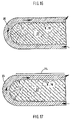
- FIGS. 18 , 19 and 20 each show different embodiments of the ventilating device 60 located on the motor vehicle seat.
- FIG. 18 illustrates a ventilating device 60 embodied as an axial fan which blows the air into the intermediate layer 10 perpendicular to the planar extension of the intermediate layer.
- Located on the underside of the air distribution layer 32 is an air intake opening in the spacer medium.
- the cross-sectional area of the opening corresponds to that of the air outlet opening of the fan.
- the opening in the structured coil mat results from a cutout in the cover layer that is optionally supported by a frame or a grid to protect the fan rotor.
- FIG. 19 shows a radial fan that blows the air from its end face into the intermediate layer 10 along the planar extension of the intermediate layer.
- the fan 60 is thus attached to the end face of the distribution layer.
- An adaptor adapts the cross-sectional shape of the fan outlet to the planar intake into the distribution layer. It is preferable for flow reasons to use a radial fan that has a narrower outlet than an axial fan has, and that deflects the air drawn in from beneath by 90 degrees when blowing it out.
- FIG. 20 illustrates a region 62 of the intermediate layer 10 which at one end 64 has a ventilating device 60 in the form of an axial fan that conveys the air through the region 62 to the other end 66 of the intermediate layer 10 .
- FIG. 21 illustrates a region 62 of the intermediate layer 10 which at one end 64 has the ventilating device 60 .
- the other end 66 guides the air into the entire intermediate layer 10 .
- the structured coil mat opens onto an enlarging connecting duct that is supported by circular coils of increasing diameter.
- the cross-section of the intake opening at the end of the duct corresponds to that of the fan's outlet opening.
- the duct can optionally also be formed by the continuation, expansion and meshing of the coils from the structured coil mat.
- FIG. 22 illustrates a schematic top view of the base layer 8 , the incorporated conducting devices 42 and heating conductor 44 .
- support elements 14 are provided which hold the applicable heating conductor 44 in position.
- the schematic top view in FIG. 23 illustrates a heating conductor 44 that is affixed to the base layer 8 in an intermediate space 90 in the intermediate layer.
- the heating conductor is laid helically on the base layer 8 .
- a number or a plurality of elongated intermediate spaces 88 , 88 ′, which are parallel to one another, are formed by the support elements 14 .
- a conducting device 42 in the form of an insulated heating conductor 44 extends in the intermediate spaces 88 , 88 ′.
- the heating conductor 44 is affixed to the base layer 8 in a transition 92 from one intermediate space 88 to the other intermediate space 88 ′. In the example embodiment shown, this attachment is accomplished by means of strips 94 of adhesive material that are arranged perpendicular to the intermediate spaces 88 , 88 ′. However, provision may also be made for the strips 94 to be embodied as electrodes.
- FIG. 24 illustrates one possible connection between the ventilating device 60 and the connecting device 35 of the intermediate layer 10 that is arranged around the cushion core 22 .
- FIG. 25 illustrates a climate control device 2 that can be inserted in a recess 86 of the cushion core 22 .
- FIG. 26 shows an especially preferred embodiment. Illustrated is a base layer 8 (alternatively, the cover layer 12 ), on which are arranged a plurality of support elements 14 .
- the support elements 14 have the shape of elongated coils that are arranged approximately parallel to one another with respect to their longitudinal axes.
- One electrical conductor 43 runs along the longitudinal axis of each support element 14 . This conductor 43 is enclosed by the support element 14 , so the conductor is well protected from external forces.
- the electrical conductor 43 can be a heating cable. In the present case, however, it is a flat cable, preferably with two conductors.
- At least one electric heating component 47 is arranged on each electrical conductor 43 .
- a plurality of heating components 47 are attached to each electrical conductor 43 .
- These are preferably PTC elements, e.g. of semiconductor ceramic of barium titanate.
- the heating components 47 of an electrical conductor 43 are preferably contacted electrically parallel to one another.
- FIG. 27 shows the electrical equivalent schematic of the arrangement from FIG. 26 .
- the plurality of electrical conductors 43 is connected to a power source through a shared bus bar 45 , forming a comb-like conductor structure.
- the bus bar 45 runs approximately perpendicular to the electrical conductors 43 at the edge of the base layer 8 or the cover layer 12 .
- FIG. 28 shows the arrangement from FIG. 26 installed in a motor vehicle seat.
- the cover layer 12 is arranged beneath a seat cover 72 .
- the support elements 14 run along the cover layer 12 in the intermediate layer 10 with the electrical conductors accommodated therein and the heating components 47 .
- a fan device 60 stands in fluid-permeable connection with the intermediate layer 10 .
- the heating components 47 heat by means of ohmic heating.
- the characteristic increase in the heater resistance of PTC components with increasing temperature results in a temperature limitation or a self-regulation of the heat output of the component and thus determines the components' final temperature.
- the heat passes, primarily by conduction, through the air enclosed in the intermediate layer 10 , and the seat cover 72 located between a passenger 96 and the heating components 47 , and to the body of the passenger.
- the air layer in the intermediate layer 10 contributes to heat distribution by convective mixing.
- air is conveyed through the intermediate layer 10 and the air-permeable seat cover 72 , and produces a convective heat transport to the passenger 96 . This action increases the rapid perception of system operation while simultaneously improving heat distribution.
- the control of the current level, switch-on times, and the PTC effect of the heating components can also be used to control the heat output.
- the heat output can be controlled by regulation of the airflow of the ventilating device 60 .
- Higher airflows bring about greater convective cooling of the PTC components, and thus, by lowering the resistance, to an increase in the heat output generated.
- the physiologically effective heat output likewise increases in a certain air volume flow region.
- provision may be made for a time delayed switch-on of the fan after a preheating phase of the PTC components. This can also contribute to an increase in the subjectively perceived response characteristics of the car seat heater. At the same time, this avoids fanning the passenger with initially cold air in the seat.
- High switch-on currents of the PTC components may necessitate series connection of a physical unit for current limitation (example: NTC semiconductor component) so that the vehicle's on-board network is not overloaded.
- FIG. 28 shows details of an attachment of a ventilating device 60 to the intermediate layer 10 .
- a cushion core 22 Arranged on a cushion core 22 are an intermediate layer 10 , a cover layer 12 , and a seat cover 72 .
- a recess 68 Provided approximately in the center of the cushion core 22 is a recess 68 , which penetrates the cushion core 22 from the side of the cushion core 22 facing away from a passenger 96 to the intermediate layer 10 .
- a ventilating device 60 is arranged in order to feed air from the side of the cushion core 22 facing away from the passenger 96 to the intermediate layer 10 .
- An anchoring means 97 is provided to attach the ventilating device 60 to the intermediate layer 10 .
- This anchoring means has a fastening device 100 on the ventilating device 60 and a retaining device 96 on the intermediate layer 10 .
- the fastening device 100 is a cable tie that engages a few windings of at least one support element 14 in the intermediate layer 10 in order to fasten the ventilating device 60 to the intermediate layer.
- This method of attachment is at the same time sturdy, cost-effective, and sufficiently yielding to mechanical loading.
- hooks or clips would also be possible for fixing the ventilating device 60 to a support element 14 or a corresponding component.
- the retaining device 98 in the present case is a short stud that is attached—preferably welded—to at least one support element 14 .
- This stud guides the ventilating device 60 into the desired position during installation and snaps it into its final position.
- a flange or similar mechanical mounting interface may also be provided.
- the anchoring means 97 also has a vibration damper 99 .
- This damper can take the form of appropriately loose cable ties as in the example embodiment.
- vibration absorbers made of rubber in the form of plates or pegs are used, which are preferably arranged between the ventilating device 60 and the intermediate layer 10 .
- Dehumidification of the seat surface can be improved by an intermediate moisture buffer in the upper spacer medium, for example in the region of the upper cover layer 12 .
- Such dehumidification can have advantageous effects especially in the event of arrival in the vehicle of a person who perspires heavily, since moisture or water vapor incident on the seat contact surface can be rapidly absorbed by the upholstery.
- the heating and ventilation of the upholstery continuously empties and dehumidifies the buffer.
- the buffer can be introduced into the layer in a number of ways. For instance, the interstices of the coils and/or the volume enclosed by the coils can be filled with a moisture-adsorbing granulate, for example activated carbon.
- the surface of the coils can also be dusted with moisture-adsorbing powder. The adhesion of the powder can be ensured by such means as melting onto the coil surface or the use of an adhesive coating.
- the coil pad can also be provided with a moisture-absorbing nonwoven cover layer.
- the air distribution layers (intermediate layers 10 ) must be firmly joined to the cushion core 22 in order to prevent shifting of the layers during installation of the cover (upholstering) or during use of the seat.
- This joining can of course be achieved in a number of ways.
- the distribution layer can be introduced in a foam molding process. This achieves full-area adhesion of the layer.
- a separator layer of film or dense textile prevents penetration of the liquid foam during the manufacturing process and keeps the channels (coil channels) open.
- the separator layer can optionally replace the downward-facing supporting layer of the coil mat in whole or in part.
- the distribution layer can be introduced in the form of a pad that is inserted in recesses in the foam core.
- the recesses constitute a negative image of the outside shape of the pad. Slipping of the pad is prevented by the interlocking connection.
- retaining mechanisms in the form of claws, hooks, or hook-and-loop closures are attached to the foam core. These retaining mechanisms are preferably fastened or foam-molded to the foam core during the foam molding process. The retaining mechanisms engage the microstructure of the distribution layer or the support elements.
- the distribution layer can optionally be fastened to the foam core by an adhesive joint.
- the supporting layer facing the foam surface can have a contour overlap beyond the spacer medium.
- the overlapping edge of the textile or film-like layer is joined to the foam core with an adhesive bond.
- a molded foam part with a comfort layer in the region of the seat contact surface can be designed in a number of ways.
- a heating medium can be area-bonded to a spacer medium.
- This composite covers the upper side of a molded foam core facing a passenger.
- the heating medium here forms the outer layer facing the surface.
- the comfort composite is preferably introduced during foam-molding in the manufacturing process, which can result in a stable, adhesive-free full-area join.
- the heating medium can optionally also be an integral component of the spacer medium.
- Possibilities for the spacer medium include, in particular, a material that is relatively soft in bending and has a pronounced compression hardness and pronounced recovery properties, so that defined open spaces remain in the cushion when a passenger is present. Nonetheless, the medium must be able to adapt relatively easily to each contour in the foam and be able to transmit compressive loads to the foam without notable spreading so that the medium does not degrade passenger seating comfort.
- the layer can, for example, take the form of a structured coil mat.
- This coil mat is produced by adhering the coils (support elements 14 ) to a textile support medium (support layer 52 , see FIG. 13 ).
- the support can face toward the foam core or toward the seat structure.
- the support layer can also be made up of one or more layers of spacer fabric.
- the fabric can be produced by punching the desired contour of the ventilated field.
- the layer can also consist of a flat, formed rubberized hair body, a bristled mat or other air-permeable materials.
- the cushion core 22 can have a structured, napped surface.
- An additional molded foam part with a structured surface can also be glued to the foam body if desired.
- the molded foam part can be manufactured from reticulated (open-cell, air-permeable) foam.
- This structure can face the foam core if desired. This achieves reduced show-through of the structure on the surface of the cover.
- the structuring can be produced through embossing of the foam or by material removal (for example by milling).
- the planar heating medium can be joined to the spacer medium by means of an adhesive layer in a laminating process.
- a heat-activated or superheated steam-activated adhesive nonwoven mat is used.
- the planar heating medium can consist of a heating conductor that is laid or glued to a planar support. It can also consist of a network of parallel carbon fibers applied to a textile support in a sewing/knitting process.
- the heating medium can optionally also be made of metallic coating on a support film.
- an alternative variant of the heating medium can comprise a conductive plastic layer.
- the plastic is characterized by a decrease in specific conductivity with increasing temperature (PTC).
- the heating current flows between two electrode layers perpendicular to the cushion surface.
- the heat output can thus differ regionally as a function of the removal of heat.
- the loops can be affixed to the support by adhesive dots at the turning points or can be held on an adhesive strip on a projecting edge of the support.
- thermoplastic surface of the thermoplastic coils is melted on by the application of heat.
- the application of heat can be accomplished, for example, by radiation, hot air or by heating of the conductor itself.
- adhesive dots are created at the contact points of the conductor to the coils, and these dots provide a mechanical connection after curing of the thermoplastic.
- the heating conductors can each have an insulating jacket that protects against abrasion.
- the attachment of the spacer medium to the foam can be embodied in the following manner.
- the distribution layer can be mixed in during the foam molding process. This achieves a full-area adhesion of the layer.
- a separator layer of film or dense textile prevents penetration of the liquid foam during the manufacturing process and keeps the channels (coil channels) open.
- the separator layer can replace the upward-facing supporting layer of the coil mat in whole or in part.
- a projecting end of the separator layer likewise protects the lateral edges of the spacer medium. The projecting end can be wrapped around the spacer medium and fixed in place on its upper side.
- a possible embodiment for the structured coil mat with filled intermediate spaces is described in detail below (see also FIGS. 11 and 12 ).
- a molded foam part with a comfort layer in the region of the seat contact surface can be designed as follows.
- the comfort layer is composed of a structured coil mat.
- the coil mat is produced by adhering the coils to a textile support medium.
- the support can face toward the foam core 22 or toward the seat structure. Adhesion of the coils to the support can also be accomplished by melting the bands of thermoplastic material.
- the structured coil mat itself is a spacer medium that is soft in bending and has high compression hardness and excellent recovery properties, so that defined open spaces remain when a passenger is present. Nonetheless, the medium can adapt easily to each contour in the foam and can transmit compressive loads to the foam without spreading. As a result, the medium does not degrade the seating comfort of the cushion.
- the open spaces in the coil mat may be filled with materials to enhance comfort. They may optionally also be used for routing the conductors and to accommodate sensors and/or actuators.
- the cushioning characteristics of the unfilled spacer material should be largely maintained, which is why only part of the available volume may be filled.
- This fill may consist of balls, granulate or flakes, for example.
- Possible filler materials include, for example, little balls of thermally insulating Styrofoam or polystyrene, which would achieve reduced heating of the foam core by solar radiation when the vehicle is parked.
- the heat stored in the cushion core has adverse thermophysiological effects on the passenger during travel.
- the upper layer has a thermal insulating effect in wintery conditions as well, so less body heat is conducted to the foam core of a cold vehicle seat.
- the fill can consist, for example, of moisture-adsorbing granulate, for example activated carbon, which can have the effect of improving comfort of the seat climate.
- Recycled foam flakes which provide good cushion comfort and adequate recovery properties, are also suitable as fill.
- a granulate/foam flake mixture as fill makes for good cushion comfort, adequate recovery properties and improved seat climate comfort.
- the fill can also consist of natural animal and/or plant fibers, which likewise can improve seat climate comfort and thermal comfort.
- the open spaces in the coil mat may be used to accommodate sensors.
- sensors for so-called seat occupancy detection are suitable for this purpose.
- these sensors are designed in the manner of a film, they are preferably arranged beneath the coil mat.
- the coil mat has the characteristic of further transmitting the pressure information downward. In this way, the sensors are protected from damage that could occur through seat use if they were installed close to the seat cover or close to the surface.
- Other sensors that may be considered also include temperature sensors for seat heaters and/or climate control, moisture sensors for controlling seat climate devices, thermostats for seat heaters and/or operating switches or pressure sensors for operating seat adjustment units and other electromechanical comfort elements.
- the open spaces in the coil mat may optionally be used to accommodate actuators, for example for massage motors.
- the open spaces in the coil mat may also be used to accommodate lines or conductors (conducting devices 42 , heating conductors 44 ).
- lines or conductors conducting devices 42 , heating conductors 44 .
- the conductors are protected from damage during installation and when the seat is used.
- the lines or conductors cannot be felt by the seat user and do not mark the upholstery surface during the course of use.
- Such lines and conductors include, in particular, heating conductors, round cables to supply seat heaters and/or seat adjustment units, flat band lines to supply seat heaters and/or seat adjustment units, supply hoses for pneumatic seat adjustment units and/or hoses carrying fluids for seat heaters and/or for seat cooling devices.
- a layer that extends continuously over the foam core creates the connection between the upper and lower sides of the cushion. This can be achieved by a component with a mat-like design (intermediate layer 10 ) that is wrapped over the front surface, or rear side surface, of the cushion core 22 .
- the cushion core 22 is rounded in such a way that, even when a person sits in it, the layer cannot buckle, which could damage lines routed through the layer. Moreover, the routing of the lines is hidden in this way, so the user can neither see nor feel then (see also FIG. 4 , for example).
- the supporting layers for the coil medium can have the following characteristics.
- the cover layer can be made of a textile medium or of foam, so that show-through on the upholstery surface of the fill granulate, lines or conductors, sensors, or the coils themselves can be prevented. This cover layer may be wide-meshed or open-celled. However, the granulate pieces should not be able to penetrate the cover layer even when the seat is being used.
- the cover layer can be vapor-permeable and water-resistant in order to protect components and media located beneath this layer from the entry of liquids, while simultaneously safeguarding comfort of the seat climate.
- cover layer a wide variety of materials can be considered that additionally improve the cushioning characteristics of the seat and the feel of the upholstery surface.
- Such materials may be nonwoven fabrics, textiles, foams or films.
- the implementation of an adhesive joint to the coil medium can have the effect of limiting the choice.
- the cover layer can also have a light-permeable film in conjunction with a perforated cover surface and a lighting medium in the seat so that illumination of the upholstery surface is possible. This lighting can be used to make visible the positions of operating controls, sensors and/or the functional state of a comfort element.
- Such lighting can improve the visual quality of the seat design.
- the geometric and design freedom of the coil structure facilitate optional substitution of the entire foam core.
- the use of multiple coil layers, large coil cross-sections and/or intermeshed coils achieves the construction of a voluminous shaped body.
- the processing of the surface profile can be undertaken as the final fabrication step due to the thermoplastic deformability.
- the composite of upholstery cover fabric and backing cloth itself may be used as the supporting layer for the coil medium.
- the seat cushion as a whole, consisting of cushion core, cover and undersprings, is replaced by a single modular unit.
- a climate control device for a passenger compartment of a vehicle may be provided, with a base layer 8 , with a cover layer 12 facing a passenger 96 that is arranged to at least partially overlap the base layer 8 , with an intermediate layer 10 that is arranged between the base layer 8 and the cover layer 12 and that has at least one support element 14 in the form of a spiral spring, which support element holds the base layer 8 and the cover layer 12 apart from one another in order to maintain a hollow space 37 between them, wherein the climate control device has at least one electrical conductor 43 which is/are arranged in the hollow space 37 .
- the climate control device has at least one electric heating element 49 and that the electrical conductor 43 and/or the electrical heating element 49 are composed of a heating conductor 44 .
- the electrical conductor 43 runs along at least a part of the support element 14 , preferably inside and/or outside the space 3 enclosed by the coils of the support element 14 .
- At least one conductor 43 is equipped with at least one heating component 47 , which preferably has a heating resistance with PTC characteristics, preferably with a semiconductor ceramic with barium titanate.
- At least one conductor 43 is equipped with a plurality of heating components 47 , which preferably are connected electrically in parallel to one another.
- the electrical conductor 43 is composed of a flat cable and/or a flat conductor.
- the device has a fan device 60 , which is fastened to the support element 14 by a direct or indirect anchoring means 97 .
- the anchoring means has a retaining device 98 —in particular a welded on retaining plate or a guide stud—which has on it at least one support element 14 on which the ventilating device 60 can be mounted, and also that the ventilating device 60 has a fastening device 100 —in particular hooks, clips or cable ties—by means of which the ventilating device 60 can be attached to the at least one support element 14 , and/or that the anchoring means 97 has at least one vibration damper 99 ′ that damps transmission of vibrations from the fan device 60 to the support element 14 , preferably in the form of rubber pegs.
Landscapes
- Engineering & Computer Science (AREA)
- Aviation & Aerospace Engineering (AREA)
- Transportation (AREA)
- Mechanical Engineering (AREA)
- Chair Legs, Seat Parts, And Backrests (AREA)
- Air-Conditioning For Vehicles (AREA)
- Seats For Vehicles (AREA)
Abstract
Description
Claims (18)
Applications Claiming Priority (5)
| Application Number | Priority Date | Filing Date | Title |
|---|---|---|---|
| DE10311862 | 2003-03-17 | ||
| DE10311862.4 | 2003-03-17 | ||
| DE20320370.4 | 2003-06-10 | ||
| DE20320370U DE20320370U1 (en) | 2003-03-17 | 2003-06-10 | Unit for air-conditioning of vehicle seats, comprises top and bottom air distribution sections joined by a connector section, with at least one of these sections incorporating an elongate cavity |
| PCT/DE2004/000541 WO2004082969A2 (en) | 2003-03-17 | 2004-03-17 | Air-conditioning device for the passenger area of a vehicle |
Publications (2)
| Publication Number | Publication Date |
|---|---|
| US20070001506A1 US20070001506A1 (en) | 2007-01-04 |
| US7510239B2 true US7510239B2 (en) | 2009-03-31 |
Family
ID=33030900
Family Applications (1)
| Application Number | Title | Priority Date | Filing Date |
|---|---|---|---|
| US10/549,467 Expired - Fee Related US7510239B2 (en) | 2003-03-17 | 2004-03-17 | Air-conditioning device for the passenger area of a vehicle |
Country Status (4)
| Country | Link |
|---|---|
| US (1) | US7510239B2 (en) |
| JP (1) | JP4053569B2 (en) |
| DE (1) | DE112004000887D2 (en) |
| WO (1) | WO2004082969A2 (en) |
Cited By (22)
| Publication number | Priority date | Publication date | Assignee | Title |
|---|---|---|---|---|
| US20070278214A1 (en) * | 2004-03-08 | 2007-12-06 | Michael Weiss | Flat Heating Element |
| US20090253362A1 (en) * | 2008-04-08 | 2009-10-08 | W.E.T Automotive Systems Ag | Ventilation means |
| US20110226751A1 (en) * | 2010-05-27 | 2011-09-22 | W.E.T. Automotive Systems, Ltd. | Heater for an automotive vehicle and method of forming same |
| US8360517B2 (en) | 2005-08-19 | 2013-01-29 | W.E.T. Automotive Systems, Ag. | Automotive vehicle seat insert |
| US8456272B2 (en) | 2010-07-15 | 2013-06-04 | W.E.T. Automotive, AG | Electric line |
| US8507831B2 (en) | 2002-11-21 | 2013-08-13 | W.E.T. Automotive Systems Ag | Heater for an automotive vehicle and method of forming same |
| US20140138992A1 (en) * | 2012-11-22 | 2014-05-22 | Hon Hai Precision Industry Co., Ltd. | Heatable seat |
| US9168852B2 (en) | 2012-12-03 | 2015-10-27 | Ford Global Technologies, Llc | Climate comfort seat assembly |
| US9191997B2 (en) | 2010-10-19 | 2015-11-17 | Gentherm Gmbh | Electrical conductor |
| US9241373B2 (en) | 2007-10-18 | 2016-01-19 | Gentherm Gmbh | Air conditioning device for seats |
| US9298207B2 (en) | 2011-09-14 | 2016-03-29 | Gentherm Gmbh | Temperature control device |
| US9420640B2 (en) | 2012-08-29 | 2016-08-16 | Gentherm Gmbh | Electrical heating device |
| US9468045B2 (en) | 2011-04-06 | 2016-10-11 | Gentherm Gmbh | Heating device for complexly formed surfaces |
| US9717115B2 (en) | 2012-06-18 | 2017-07-25 | Gentherm Gmbh | Textile or non-textile sheet and/or fabric with electrical function |
| US9821832B2 (en) | 2012-12-20 | 2017-11-21 | Gentherm Gmbh | Fabric with electrical function element |
| WO2018085104A1 (en) | 2016-11-01 | 2018-05-11 | Gentherm Incorporated | Flexible heater and method of integration |
| US20180162244A1 (en) * | 2015-06-17 | 2018-06-14 | Volkswagen Aktiengesellschaft | Method and device for operating a seat ventilation device, seat ventilation device |
| US10201039B2 (en) | 2012-01-20 | 2019-02-05 | Gentherm Gmbh | Felt heater and method of making |
| US10479243B2 (en) * | 2017-12-05 | 2019-11-19 | Ford Global Technologies, Llc | Air channel thermocomfort foam pad |
| US10625643B2 (en) | 2017-06-14 | 2020-04-21 | Gentherm Gmbh | Conditioning system with blower attachment system and method of attachment |
| US10953775B1 (en) | 2020-02-04 | 2021-03-23 | Ford Global Technologies, Llc | Seat assembly with cushioned components having an integrated air channeling system |
| US11388814B2 (en) | 2017-02-07 | 2022-07-12 | Gentherm Gmbh | Electrically conductive film |
Families Citing this family (13)
| Publication number | Priority date | Publication date | Assignee | Title |
|---|---|---|---|---|
| US7370911B2 (en) | 2003-10-17 | 2008-05-13 | W.E.T. Automotive Systems, Ag | Automotive vehicle seat insert |
| DE10350146B4 (en) * | 2003-10-28 | 2006-05-04 | Daimlerchrysler Ag | Vehicle seat for a motor vehicle |
| TWI356780B (en) * | 2005-06-06 | 2012-01-21 | Combi Corp | Child seat, ventilation portion structure of artic |
| DE102007056465B4 (en) * | 2007-11-22 | 2010-06-02 | I.G. Bauerhin Gmbh | Motor vehicle seat with seat heating |
| DE112009002158B4 (en) * | 2008-09-23 | 2012-10-18 | Lear Corp. | Ventilated seat assembly and method for controlling the same |
| JP5909987B2 (en) * | 2011-10-19 | 2016-04-27 | トヨタ紡織株式会社 | Components for vehicle seats |
| JP5985411B2 (en) * | 2012-02-22 | 2016-09-06 | トヨタ紡織株式会社 | Cushion pad for vehicle seat |
| CN106663834A (en) | 2014-07-22 | 2017-05-10 | 瑞克锐斯株式会社 | Silicone secondary battery unit and battery module for electrical vehicle using same |
| US10674830B1 (en) * | 2017-09-22 | 2020-06-09 | Tramec Termico Technologies, L.L.C. | Self-regulating heated seat cushion |
| JP7295452B2 (en) * | 2018-04-09 | 2023-06-21 | テイ・エス テック株式会社 | seat |
| KR20200033578A (en) * | 2018-09-20 | 2020-03-30 | 현대트랜시스 주식회사 | Ventilation seat for vehicle |
| ES2909384T3 (en) | 2018-11-20 | 2022-05-06 | Motherson Innovations Co Ltd | Coating component and air conditioning system for lining and controlling the temperature of an interior of a passenger transport vehicle, in particular a motor vehicle |
| JP7481664B2 (en) * | 2021-11-15 | 2024-05-13 | テイ・エス テック株式会社 | Sheet |
Citations (15)
| Publication number | Priority date | Publication date | Assignee | Title |
|---|---|---|---|---|
| US1541213A (en) | 1922-12-11 | 1925-06-09 | Erskine P Harley | Seat cushion |
| US2922466A (en) | 1958-06-02 | 1960-01-26 | Oliver F Marston | Seat cushion |
| US2992604A (en) | 1958-06-09 | 1961-07-18 | Trotman | Forced air under body ventilating device |
| US5934748A (en) * | 1997-01-31 | 1999-08-10 | Daimler-Benz Aktiengesellschaft | Vehicle seat with temperature and ventilation control and method of operation |
| US6229123B1 (en) * | 1998-09-25 | 2001-05-08 | Thermosoft International Corporation | Soft electrical textile heater and method of assembly |
| US6291803B1 (en) * | 1999-03-01 | 2001-09-18 | Bertrand Faure Equipments Sa | Method and system of regulating heat in a vehicle seat |
| US6439658B1 (en) * | 1999-11-05 | 2002-08-27 | Webasto Systemkomponenten Gmbh | Ventilation device for the seat of a motor vehicle |
| US20020145312A1 (en) * | 2001-04-04 | 2002-10-10 | Gielda Thomas Paul | Climatized seat with vortex tube |
| DE10228406A1 (en) | 2001-06-25 | 2003-01-02 | Bernhard Scheuring | Structured element, comprises a band shaped member made of plastic, with reinforcing fibers, and a thermoplastic coating |
| US6578910B2 (en) * | 2000-03-02 | 2003-06-17 | Lear Corporation | Ventilation seat |
| US6619736B2 (en) * | 2000-02-26 | 2003-09-16 | W.E.T. Automotive Systems Ag | Vehicle seat ventilation system |
| US6676207B2 (en) * | 2001-02-05 | 2004-01-13 | W.E.T. Automotive Systems Ag | Vehicle seat |
| US20040036325A1 (en) * | 2000-12-23 | 2004-02-26 | Stephan Diemer | Surface heating system and method for producing it and a heatable object |
| US20040104607A1 (en) * | 2002-08-15 | 2004-06-03 | Nhk Spring Co., Ltd. | Breathable seat |
| US6828528B2 (en) * | 2001-07-18 | 2004-12-07 | W.E.T. Automotive Systems Ag | Electric circuit to control an air-conditioned seat |
Family Cites Families (6)
| Publication number | Priority date | Publication date | Assignee | Title |
|---|---|---|---|---|
| US541213A (en) * | 1895-06-18 | Bridge construction | ||
| SE463090B (en) * | 1986-09-17 | 1990-10-08 | Scandmec Mecania Ab | Procedure for producing a heated cushion having one or more resilient layers provided with heating cable |
| DE3820095A1 (en) * | 1988-06-13 | 1989-12-21 | Gore W L & Ass Gmbh | COVER MATERIAL FOR UPHOLSTERED BEDS AND SEATS |
| DE4014550A1 (en) * | 1989-05-16 | 1990-11-22 | Volkswagen Ag | Upholstered car seat with air induction fan for perspiration removal - uses internal negative pressure source and simple seat modification for searching aeration of porous upholstery |
| DE19805174C1 (en) * | 1998-02-10 | 1999-06-02 | Daimler Chrysler Ag | Motor vehicle heated seat with seat and backrest cushions containing air passages and electric fans |
| DE19847384C1 (en) * | 1998-10-14 | 2000-06-21 | Daimler Chrysler Ag | Upholstery for seat part and / or backrest of a vehicle seat |
-
2004
- 2004-03-17 DE DE112004000887T patent/DE112004000887D2/en not_active Expired - Fee Related
- 2004-03-17 JP JP2005518183A patent/JP4053569B2/en not_active Expired - Fee Related
- 2004-03-17 WO PCT/DE2004/000541 patent/WO2004082969A2/en not_active Ceased
- 2004-03-17 US US10/549,467 patent/US7510239B2/en not_active Expired - Fee Related
Patent Citations (15)
| Publication number | Priority date | Publication date | Assignee | Title |
|---|---|---|---|---|
| US1541213A (en) | 1922-12-11 | 1925-06-09 | Erskine P Harley | Seat cushion |
| US2922466A (en) | 1958-06-02 | 1960-01-26 | Oliver F Marston | Seat cushion |
| US2992604A (en) | 1958-06-09 | 1961-07-18 | Trotman | Forced air under body ventilating device |
| US5934748A (en) * | 1997-01-31 | 1999-08-10 | Daimler-Benz Aktiengesellschaft | Vehicle seat with temperature and ventilation control and method of operation |
| US6229123B1 (en) * | 1998-09-25 | 2001-05-08 | Thermosoft International Corporation | Soft electrical textile heater and method of assembly |
| US6291803B1 (en) * | 1999-03-01 | 2001-09-18 | Bertrand Faure Equipments Sa | Method and system of regulating heat in a vehicle seat |
| US6439658B1 (en) * | 1999-11-05 | 2002-08-27 | Webasto Systemkomponenten Gmbh | Ventilation device for the seat of a motor vehicle |
| US6619736B2 (en) * | 2000-02-26 | 2003-09-16 | W.E.T. Automotive Systems Ag | Vehicle seat ventilation system |
| US6578910B2 (en) * | 2000-03-02 | 2003-06-17 | Lear Corporation | Ventilation seat |
| US20040036325A1 (en) * | 2000-12-23 | 2004-02-26 | Stephan Diemer | Surface heating system and method for producing it and a heatable object |
| US6676207B2 (en) * | 2001-02-05 | 2004-01-13 | W.E.T. Automotive Systems Ag | Vehicle seat |
| US20020145312A1 (en) * | 2001-04-04 | 2002-10-10 | Gielda Thomas Paul | Climatized seat with vortex tube |
| DE10228406A1 (en) | 2001-06-25 | 2003-01-02 | Bernhard Scheuring | Structured element, comprises a band shaped member made of plastic, with reinforcing fibers, and a thermoplastic coating |
| US6828528B2 (en) * | 2001-07-18 | 2004-12-07 | W.E.T. Automotive Systems Ag | Electric circuit to control an air-conditioned seat |
| US20040104607A1 (en) * | 2002-08-15 | 2004-06-03 | Nhk Spring Co., Ltd. | Breathable seat |
Cited By (40)
| Publication number | Priority date | Publication date | Assignee | Title |
|---|---|---|---|---|
| US8766142B2 (en) | 2002-11-21 | 2014-07-01 | W.E.T. Automotive Systems Ag | Heater for an automotive vehicle and method of forming same |
| US9315133B2 (en) | 2002-11-21 | 2016-04-19 | Gentherm Gmbh | Heater for an automotive vehicle and method of forming same |
| US8507831B2 (en) | 2002-11-21 | 2013-08-13 | W.E.T. Automotive Systems Ag | Heater for an automotive vehicle and method of forming same |
| US9578690B2 (en) | 2002-11-21 | 2017-02-21 | Gentherm Gmbh | Heater for an automotive vehicle and method of forming same |
| US20070278214A1 (en) * | 2004-03-08 | 2007-12-06 | Michael Weiss | Flat Heating Element |
| US8288693B2 (en) | 2004-03-08 | 2012-10-16 | W.E.T. Automotive Systems Ag | Flat heating element |
| US9440567B2 (en) | 2005-08-19 | 2016-09-13 | Gentherm Gmbh | Automotive vehicle seat insert |
| US8360517B2 (en) | 2005-08-19 | 2013-01-29 | W.E.T. Automotive Systems, Ag. | Automotive vehicle seat insert |
| US9241373B2 (en) | 2007-10-18 | 2016-01-19 | Gentherm Gmbh | Air conditioning device for seats |
| US20090253362A1 (en) * | 2008-04-08 | 2009-10-08 | W.E.T Automotive Systems Ag | Ventilation means |
| US9085255B2 (en) * | 2008-04-08 | 2015-07-21 | Gentherm Gmbh | Ventilation means |
| US8702164B2 (en) | 2010-05-27 | 2014-04-22 | W.E.T. Automotive Systems, Ltd. | Heater for an automotive vehicle and method of forming same |
| US8544942B2 (en) | 2010-05-27 | 2013-10-01 | W.E.T. Automotive Systems, Ltd. | Heater for an automotive vehicle and method of forming same |
| US9657963B2 (en) | 2010-05-27 | 2017-05-23 | Gentherm Canada Ltd. | Heater for an automotive vehicle and method of forming same |
| DE112011101808T5 (en) | 2010-05-27 | 2013-05-16 | W.E.T.Automotive Systems Ltd. | Heating device for a motor vehicle and method for its production |
| WO2011149680A1 (en) | 2010-05-27 | 2011-12-01 | W.E.T. Automotive Systems, Ltd. | Heater for an automotive vehicle and method of forming same |
| US20110226751A1 (en) * | 2010-05-27 | 2011-09-22 | W.E.T. Automotive Systems, Ltd. | Heater for an automotive vehicle and method of forming same |
| US8456272B2 (en) | 2010-07-15 | 2013-06-04 | W.E.T. Automotive, AG | Electric line |
| US9191997B2 (en) | 2010-10-19 | 2015-11-17 | Gentherm Gmbh | Electrical conductor |
| US9468045B2 (en) | 2011-04-06 | 2016-10-11 | Gentherm Gmbh | Heating device for complexly formed surfaces |
| US9298207B2 (en) | 2011-09-14 | 2016-03-29 | Gentherm Gmbh | Temperature control device |
| US10201039B2 (en) | 2012-01-20 | 2019-02-05 | Gentherm Gmbh | Felt heater and method of making |
| US9717115B2 (en) | 2012-06-18 | 2017-07-25 | Gentherm Gmbh | Textile or non-textile sheet and/or fabric with electrical function |
| US9420640B2 (en) | 2012-08-29 | 2016-08-16 | Gentherm Gmbh | Electrical heating device |
| US9022464B2 (en) * | 2012-11-22 | 2015-05-05 | Tsinghua University | Heatable seat |
| US20140138992A1 (en) * | 2012-11-22 | 2014-05-22 | Hon Hai Precision Industry Co., Ltd. | Heatable seat |
| US9168852B2 (en) | 2012-12-03 | 2015-10-27 | Ford Global Technologies, Llc | Climate comfort seat assembly |
| US9821832B2 (en) | 2012-12-20 | 2017-11-21 | Gentherm Gmbh | Fabric with electrical function element |
| US20180162244A1 (en) * | 2015-06-17 | 2018-06-14 | Volkswagen Aktiengesellschaft | Method and device for operating a seat ventilation device, seat ventilation device |
| WO2018085104A1 (en) | 2016-11-01 | 2018-05-11 | Gentherm Incorporated | Flexible heater and method of integration |
| DE112017005518T5 (en) | 2016-11-01 | 2019-08-22 | Gentherm Incorporated | FLEXIBLE HEATING AND INTEGRATION PROCEDURE |
| DE112017005518B4 (en) | 2016-11-01 | 2026-03-05 | Gentherm Gmbh | FLEXIBLE HEATING AND INTEGRATION METHOD |
| US11388814B2 (en) | 2017-02-07 | 2022-07-12 | Gentherm Gmbh | Electrically conductive film |
| US11751327B2 (en) | 2017-02-07 | 2023-09-05 | Gentherm Gmbh | Electrically conductive film |
| US12177967B2 (en) | 2017-02-07 | 2024-12-24 | Gentherm Gmbh | Electrically conductive film |
| US10710480B2 (en) | 2017-06-14 | 2020-07-14 | Gentherm Gmbh | Conditioning system with blower connection assembly including a distribution member and method of attachment |
| US10625643B2 (en) | 2017-06-14 | 2020-04-21 | Gentherm Gmbh | Conditioning system with blower attachment system and method of attachment |
| US10773618B2 (en) | 2017-12-05 | 2020-09-15 | Ford Global Technologies, Llc | Air channel thermocomfort foam pad |
| US10479243B2 (en) * | 2017-12-05 | 2019-11-19 | Ford Global Technologies, Llc | Air channel thermocomfort foam pad |
| US10953775B1 (en) | 2020-02-04 | 2021-03-23 | Ford Global Technologies, Llc | Seat assembly with cushioned components having an integrated air channeling system |
Also Published As
| Publication number | Publication date |
|---|---|
| DE112004000887D2 (en) | 2006-06-29 |
| WO2004082969A3 (en) | 2005-02-24 |
| JP4053569B2 (en) | 2008-02-27 |
| WO2004082969A2 (en) | 2004-09-30 |
| US20070001506A1 (en) | 2007-01-04 |
| JP2006513012A (en) | 2006-04-20 |
Similar Documents
| Publication | Publication Date | Title |
|---|---|---|
| US7510239B2 (en) | Air-conditioning device for the passenger area of a vehicle | |
| US7695062B2 (en) | Device for receiving functional elements | |
| EP0730422B1 (en) | Variable temperature seat | |
| KR100554640B1 (en) | Automotive vehicle seat and blower module for such an automotive vehicle seat | |
| US9415712B2 (en) | Ventilation system | |
| US7827805B2 (en) | Seat climate control system | |
| US9738191B2 (en) | Ventilated and heated vehicle seat assembly | |
| US7131689B2 (en) | Automotive vehicle seating comfort system | |
| US20060151455A1 (en) | Air-conditioning device for the passenger area of a vehicle | |
| US20060158011A1 (en) | Molded layer for a seat insert | |
| US20090033130A1 (en) | Fluid delivery systems for climate controlled seats | |
| US20070158981A1 (en) | Vehicle seat with cushioning layer | |
| US20060214480A1 (en) | Vehicle seat with thermal elements | |
| KR101054489B1 (en) | Ventilated seat with front breathable material | |
| US20080111403A1 (en) | Module for a cushion | |
| JP6472464B2 (en) | Ventilation device for supplying air to passengers sitting in a vehicle seat | |
| WO2015123585A1 (en) | Conductive convective climate controlled seat | |
| WO2004041585A2 (en) | An arrangement and method for providing an air flow within an upholstered seat | |
| CN1902066B (en) | Device for air conditioning a motor vehicle seat | |
| DE20320372U1 (en) | Device for air-conditioning a vehicle seat which has a core cushion, comprises base, intermediate and cover layers, and is joined to the core cushion by material bonds | |
| DE10326445B4 (en) | Device for air conditioning a vehicle seat | |
| CN100467306C (en) | Device for receiving functional elements | |
| KR200357474Y1 (en) | A Vehicle seat with cooling/heating device | |
| KR20170058380A (en) | Electrical heating device with flat textile carrier | |
| DE20320371U1 (en) | Arrangement for accommodating functional elements in parts of a vehicle interior, comprises an intermediate layer with at least one support element for load transfer between base and cover layers |
Legal Events
| Date | Code | Title | Description |
|---|---|---|---|
| AS | Assignment |
Owner name: W.E.T. AUTOMOTIVE SYSTEMS AG, GERMANY Free format text: ASSIGNMENT OF ASSIGNORS INTEREST;ASSIGNOR:STOWE, STEFAN;REEL/FRAME:017345/0045 Effective date: 20051012 |
|
| STCF | Information on status: patent grant |
Free format text: PATENTED CASE |
|
| FPAY | Fee payment |
Year of fee payment: 4 |
|
| AS | Assignment |
Owner name: GENTHERM GMBH, GERMANY Free format text: CHANGE OF NAME;ASSIGNOR:W.E.T. AUTOMOTIVE SYSTEMS AG;REEL/FRAME:035496/0605 Effective date: 20140428 |
|
| FPAY | Fee payment |
Year of fee payment: 8 |
|
| FEPP | Fee payment procedure |
Free format text: MAINTENANCE FEE REMINDER MAILED (ORIGINAL EVENT CODE: REM.); ENTITY STATUS OF PATENT OWNER: LARGE ENTITY |
|
| LAPS | Lapse for failure to pay maintenance fees |
Free format text: PATENT EXPIRED FOR FAILURE TO PAY MAINTENANCE FEES (ORIGINAL EVENT CODE: EXP.); ENTITY STATUS OF PATENT OWNER: LARGE ENTITY |
|
| STCH | Information on status: patent discontinuation |
Free format text: PATENT EXPIRED DUE TO NONPAYMENT OF MAINTENANCE FEES UNDER 37 CFR 1.362 |
|
| FP | Lapsed due to failure to pay maintenance fee |
Effective date: 20210331 |