US7509082B2 - Image forming apparatus and method of controlling the same - Google Patents
Image forming apparatus and method of controlling the same Download PDFInfo
- Publication number
- US7509082B2 US7509082B2 US11/468,682 US46868206A US7509082B2 US 7509082 B2 US7509082 B2 US 7509082B2 US 46868206 A US46868206 A US 46868206A US 7509082 B2 US7509082 B2 US 7509082B2
- Authority
- US
- United States
- Prior art keywords
- image forming
- sheet
- image
- color
- corrected
- Prior art date
- Legal status (The legal status is an assumption and is not a legal conclusion. Google has not performed a legal analysis and makes no representation as to the accuracy of the status listed.)
- Expired - Fee Related, expires
Links
Images


Classifications
-
- G—PHYSICS
- G03—PHOTOGRAPHY; CINEMATOGRAPHY; ANALOGOUS TECHNIQUES USING WAVES OTHER THAN OPTICAL WAVES; ELECTROGRAPHY; HOLOGRAPHY
- G03G—ELECTROGRAPHY; ELECTROPHOTOGRAPHY; MAGNETOGRAPHY
- G03G15/00—Apparatus for electrographic processes using a charge pattern
- G03G15/01—Apparatus for electrographic processes using a charge pattern for producing multicoloured copies
- G03G15/0142—Structure of complete machines
- G03G15/0178—Structure of complete machines using more than one reusable electrographic recording member, e.g. one for every monocolour image
- G03G15/0194—Structure of complete machines using more than one reusable electrographic recording member, e.g. one for every monocolour image primary transfer to the final recording medium
-
- G—PHYSICS
- G03—PHOTOGRAPHY; CINEMATOGRAPHY; ANALOGOUS TECHNIQUES USING WAVES OTHER THAN OPTICAL WAVES; ELECTROGRAPHY; HOLOGRAPHY
- G03G—ELECTROGRAPHY; ELECTROPHOTOGRAPHY; MAGNETOGRAPHY
- G03G2215/00—Apparatus for electrophotographic processes
- G03G2215/01—Apparatus for electrophotographic processes for producing multicoloured copies
- G03G2215/0103—Plural electrographic recording members
- G03G2215/0119—Linear arrangement adjacent plural transfer points
-
- G—PHYSICS
- G03—PHOTOGRAPHY; CINEMATOGRAPHY; ANALOGOUS TECHNIQUES USING WAVES OTHER THAN OPTICAL WAVES; ELECTROGRAPHY; HOLOGRAPHY
- G03G—ELECTROGRAPHY; ELECTROPHOTOGRAPHY; MAGNETOGRAPHY
- G03G2215/00—Apparatus for electrophotographic processes
- G03G2215/01—Apparatus for electrophotographic processes for producing multicoloured copies
- G03G2215/0151—Apparatus for electrophotographic processes for producing multicoloured copies characterised by the technical problem
- G03G2215/0158—Colour registration
- G03G2215/0161—Generation of registration marks
Definitions
- the present invention relates to a technique of correcting registration in an image forming apparatus using an electrostatic recording system, an electrophotographic recording system or the like.
- a color image is formed by superposing images of different colors on one another. This image forming requires forming the plurality of images of different colors at correct positions without relative misalignment.
- ten pattern images are formed with respect to nine periods of a drive roller 32 , as shown in FIG. 13 .
- Sampling times are thereby distributed uniformly in one period of the drive roller, as shown in FIG. 14 .
- the influence of image expansion and contraction is suitably cancelled. More specifically, “misalignments” due to image expansion and contraction are cancelled as between phases p 1 and p 6 , phases p 2 and p 7 , phases p 3 and p 8 , phases p 4 and p 9 , and phases p 5 and p 10 .
- the method of increasing sample values of the pattern images and performing averaging process as described above is effective in reducing the influence of image extraction and contraction.
- sample values are excessively increased, a problem arises that the correction processing time is increased and the consumption of toners for forming the pattern images is increased. Further, an increased load is imposed on the cleaning member for cleaning of the formed pattern images. Therefore it is desirable to minimize the number of pattern images.
- the pattern image it is preferable to form the pattern image in a space area (sheet-to-sheet space) arisen between the area in which the kth (k: an integer) output image is formed and the area in which (k+1)th output image is formed in order to correct registration while maintaining the desired productivity.
- the pattern image is formed in the sheet-to-sheet space, there is a possibility of a restriction on the length of the image forming medium in the medium conveying direction, the width of the sheet-to-sheet space (the length in the conveying direction) or the frequency with which the pattern image is repeatedly formed, depending image forming modes.
- the pattern image is formed at a suitable position according to the cycle of rotation of the drive roller, the bad influence of the drive roller cannot be cancelled and an improvement in correction accuracy cannot be expected.
- an image forming apparatus including: a rotating member which is one of an intermediate transfer member and a rotating conveyer which conveys an image forming medium, the intermediate transfer member temporarily holds an image to be transferred onto the image forming medium; a drive roller which drives the rotating member; a plurality of image forming sections which respectively form images of different colors on the rotating member or the image forming medium; a control section which forms a pattern image by using the image forming sections in a space area on the rotating member arisen between a first area in which an image corresponding to the first image forming medium is formed and a second area in which an image corresponding to the second image forming medium is formed; and a correction section which corrects the positions at which the images are formed on the basis of a plurality of the formed pattern images.
- the control section controls the image forming sections so that the image forming sections form the pattern image the number of times n such that N is a value close to an integer.
- the suitable number of times n the pattern image is formed is determined by considering parameters, e.g. the length L of the image forming medium, the width d of the space area and the conveying distance A passed by the rotating member while the drive roller rotates through one revolution, with respect to each image forming mode. In this way, it is possible to execute registration correction with accuracy while reducing the loads on the sections of the image forming apparatus.
- FIG. 1 is a sectional view of essential portions of an example of an image forming apparatus according to an embodiment of the present invention
- FIG. 2 is a schematic diagram showing a registration correction mechanism according to the embodiment
- FIG. 3 is a diagram showing an example of formation of pattern images for registration correction on an intermediate transfer member according to the embodiment
- FIG. 4 is a diagram showing an example of the pattern images (registration marks) according to the embodiment.
- FIG. 5 is a diagram for explaining the placement of the pattern images (registration marks and density correction patches) according to the embodiment
- FIG. 6 is a diagram for explaining a phase shift according to the embodiment.
- FIG. 7 is a diagram showing the relationship between the phase of rotation of a drive roller and pattern image (registration mark) detection timing according to the embodiment
- FIG. 8 is a diagram for explaining another phase shift according to the embodiment.
- FIG. 9 is a flowchart showing an example of registration correction processing according to the embodiment.
- FIG. 10 is a diagram for explaining a phase shift in a second embodiment of the present invention.
- FIG. 11 is a flowchart showing an example of registration correction processing according to a third embodiment of the present invention.
- FIG. 12 is a diagram for explaining the placement of pattern images (registration marks and density correction patches) according to a fourth embodiment of the present invention.
- FIG. 13 is a diagram for explaining a phase shift in the conventional art.
- FIG. 14 is a diagram for explaining the number of sampling times in the conventional art.
- Embodiments of the present invention useful for understanding of the present invention will be described below. Needless to say, the present invention is not limited to the embodiments described below.
- the first embodiment will be described with respect to a case where a predetermined integer m is equal to S ⁇ 1 in particular. S is the total number of image forming sections.
- the second embodiment will be described with respect to a case where the predetermined integer m is equal to 1.
- the fourth embodiment will be described with respect to a case where a plurality of densities of each color are set and detected.
- FIG. 1 is a sectional view of essential portions of an example of an image forming apparatus according to the embodiment.
- This example of the image forming apparatus is a color image forming apparatus 100 having four image forming sections arranged side by side. That is, an image output section 1 P is constituted by an image forming unit 10 divided generally into four image forming sections, a sheet feed unit 20 , an intermediate transfer unit 30 , a fixing unit 40 and a control unit 70 .
- the image forming unit 10 has main components described below.
- Photosensitive drums 11 a , 11 b , 11 c , and 11 d are image bearing bodies rotated in the directions of the arrow.
- Each of the photosensitive drums 11 a , 11 b , 11 c , and 11 d is axially supported at its center.
- Primary chargers 12 a , 12 b , 12 c , and 12 d , optical systems 13 a , 13 b , 13 c , and 13 d and development devices 14 a , 14 b , 14 c , and 14 d are disposed in the direction of rotation of the photosensitive drums 11 a to 11 d so as to face the outer peripheral surfaces of the photosensitive drums 11 a to 11 d.
- the primary chargers 12 a to 12 d uniform amounts of charge are applied to the surfaces of the photosensitive drums 11 a to 11 d . Subsequently, the photosensitive drums 11 a to 11 d are exposed by the optical systems 13 a to 13 d to light beams, e.g., laser beams modulated according to a recording image signal. Electrostatic latent images are thereby formed on the photosensitive drums 11 a to 11 d .
- the electrostatic latent images are developed as toner images by the development device 14 a to 14 d respectively containing developers (toners) of four colors: yellow, cyan, magenta and black.
- image primary transfer regions Ta, Tb, Tc, and Td the developed toner images are transferred onto the intermediate transfer belt 31 provided as an intermediate transfer member.
- image primary transfer regions Ta, Tb, Tc, and Td toners remaining on the photosensitive drums 11 a to 11 d without being transferred onto an image forming medium P are scraped off by cleaning devices 15 a , 15 b , 15 c , and 15 d .
- cleaning devices 15 a , 15 b , 15 c , and 15 d are scraped off by cleaning devices 15 a , 15 b , 15 c , and 15 d .
- the sheet feed unit 20 has cassettes 21 a and 21 b for storage of image forming medium P, a manual feed tray 27 , and pickup rollers 22 a , 22 b , and 26 for feeding sheets of image forming medium P one by one from the cassettes 21 a and 21 b and the manual feed tray 27 .
- Pairs of sheet feed rollers 23 and sheet feed guide 24 convey the image forming medium P fed out of the pickup roller 22 a , 22 b , or 26 to registration rollers 25 a and 25 b .
- the registration rollers 25 a and 25 b feed the image forming medium P to a secondary transfer region Te according to image forming timing in the image forming unit 10 .
- the intermediate transfer unit 30 has the intermediate transfer belt 31 provided as an intermediate transfer member or a bearing body.
- the intermediate transfer belt 31 is wrapped around a driver roller 32 through which a drive force is transmitted to the intermediate transfer belt 31 , a backup roller 62 , a tension roller 33 and a secondary transfer inner roller 34 .
- the backup roller 62 faces a detection sensor 60 .
- the tension roller 33 applies a suitable tension to the intermediate transfer belt 31 by the urging force of a spring (not shown).
- the secondary transfer roller 34 faces the secondary transfer region Te, with the intermediate transfer belt 31 interposed therebetween.
- the intermediate transfer belt 31 is selected, for example, from polyimide (PI), polyvinylidene fluoride (PVdF) and the like.
- a primary transfer surface A is formed between the drive roller 32 and the backup roller 62 .
- the drive roller 32 is a metallic roller having a several millimeter thick rubber (urethane or chloroprene) coating formed on its surface for prevention of slippage from the intermediate transfer belt 31 .
- the drive roller 32 is driven and rotated by a pulse motor (not shown).
- Alignment of the tension roller 33 urged by a pressing mechanism can be controlled to correct meandering of the intermediate transfer belt 31 .
- primary transfer devices 35 a to 35 d are disposed on the back sides of the intermediate transfer belt 31 .
- a cleaning device 50 for cleaning the image formation surface of the intermediate transfer belt 31 is disposed downstream of the secondary transfer region Te on the intermediate transfer belt 31 .
- the cleaning device 50 is constituted by a cleaner blade 51 and a waste toner box 52 which stores a waste toner. Polyurethane rubber or the like is used as the material of the cleaner blade 51 .
- the fixing unit 40 is constituted by a fixing roller 41 a , a pressure roller 41 b pressed against the fixing roller 41 a , a conveying guide 43 , inner discharge rollers 44 and outer discharge rollers 45 .
- the fixing roller 41 a has a heat source such as a halogen heater provided therein.
- the pressure roller 41 b may also have a heat source.
- the conveying guide 43 guides the image forming medium P to a nip between the fixing roller 41 a and the pressure roller 41 b .
- the inner discharge rollers 44 and the outer discharge rollers 45 guide the image forming medium P discharged from the fixing roller 41 a and the pressure roller 41 b to discharge the medium out of the apparatus.
- the control unit 70 is constituted by a control board, a motor drive board (not shown) and other components for controlling the operations of the mechanisms in each unit.
- various control circuit components including a central processing unit (CPU), a read-only memory (ROM) and a random access memory (RAM) are mounted on the control board.
- a control program such as a piece of firmware is stored in the ROM.
- the toner image formed on the photosensitive drum 11 d in the uppermost upstream position in the direction of rotation of the intermediate transfer belt 31 is transferred onto the intermediate transfer belt 31 by primary transfer.
- the toner image transferred onto the intermediate transfer belt 31 by primary transfer is carried to the next primary transfer region Tc.
- image forming is performed with a delay corresponding to the time period required to carry the toner image between the image forming sections. That is, the next toner image is transferred by being correctly positioned on the toner image already formed.
- registration Such adjustment of the positions at which a plurality of color images of different colors are formed is called registration.
- the same steps are repeated to complete primary transfer of the four color toner images onto the intermediate transfer belt 31 .
- the image forming medium P thereafter enters the secondary transfer region Te to be brought into contact with the intermediate transfer belt 31 .
- a high voltage is applied to a secondary transfer device 36 .
- the four color toner images formed on the intermediate transfer belt 31 by the above-described process are thereby transferred onto the surface of the image forming medium P.
- the image forming medium P bearing the transferred toner images is guided to the nip in the fixing unit 40 with accuracy by the conveying guide 43 .
- the toner images are fixed on the surface of the image forming medium P by heat from the pair of rollers 41 a and 41 b in the fixing unit 40 and by the pressure of the nip.
- the image forming medium P on which the toner images are fixed is carried by the inner discharge roller 44 and the outer discharge roller 45 to be discharged out of the image forming apparatus.
- FIG. 2 is a schematic diagram showing a registration correction mechanism according to the embodiment.
- the control unit 70 includes an image position detection circuit 81 , a correction amount computation circuit 82 , a control circuit 83 and other components as a registration correction mechanism.
- Detection sensors 60 and 61 are used to read out pattern images for a registration correction.
- Each of detection sensors 60 and 61 is constituted by a light emitting diode (LED) provided as a light source and a light receiving element which detects reflected light.
- the image position detection circuit 81 detects the positions at which pattern images are formed on the basis of electrical signals output from the detection sensors 60 and 61 .
- the image position detection circuit 81 also computes an amount of error in color registration from the pattern image formation positions.
- the correction amount computation circuit 82 computes, from the computed amount of error in color registration, an amount of correction of the formation position with respect to the color to be corrected.
- the control circuit 83 controls the optical system 13 according to the computed amount of correction. For example, a lens or a mirror of the optical system 13 or timing of light emission from the optical system 13 relating to the image formation position is adjusted. At least one detection sensor 60 is required. However, it is preferable to provide a plurality of detection sensors to improve the correction accuracy.
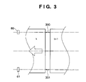
- FIG. 3 is a diagram showing an example of formation of pattern images for registration correction (hereinafter referred to as “registration mark”) on the intermediate transfer member according to the embodiment.
- registration marks 300 and 301 are formed in a space area arisen between the area for formation of the kth (k: integer) image and the area for formation of the (k+1)th image on the intermediate transfer belt 31 (hereinafter referred to as “sheet-to-sheet space”).
- sheet-to-sheet space The arrow in the figure indicates the carrying direction of images.
- the registration marks 300 and 301 are formed so as to coincide with the positions at which detection with the detection sensors 60 and 61 can be performed. When the registration marks 300 and 301 pass immediately below the detection sensors 60 and 61 , predetermined electrical signals are output from the detection sensors 60 and 61 .
- FIG. 4 is a diagram showing an example of the pattern images (registration marks) according to the embodiment.
- each of the registration marks 300 and 301 has a slanting line Ca of a color to be corrected formed between slanting lines Ka and Kb of a reference color, and a slanting line Cb of a color to be corrected formed between slanting lines Kc and Kd of the reference color.
- a case will be considered in which a color registration error of ⁇ V has occurred in the main scanning direction (a direction perpendicular to the sheet conveying direction), and in which a color registration error of ⁇ H also has occurred in the sub scanning direction (a direction parallel to the sheet conveying direction). That is, images of lines Ca and Cb are formed at positions respectively shifted by ⁇ V and ⁇ H from lines Cas and Cbs at the ideal positions. Portions of the electrical signals output from the detection sensors 60 and 61 at this time in correspondence with the non-image portions of the mark (the base portion of the intermediate transfer belt 31 ) are “Hi”.
- portions of the electrical signals corresponding to the image portions of the mark are “Lo”. This means that the reflectivity of the base portion of the intermediate transfer belt 31 is higher than that of the toner images.
- the correction amount computation circuit 82 computes the amounts of correction of the optical system 13 necessary for reducing the color registration errors ⁇ V and ⁇ H.
- the control circuit 83 corrects the position of the lens or the mirror of optical system 13 or timing of light emission from the optical system 13 according to the computed amounts of correction.
- the correction amount computation circuit 82 and the control circuit 83 function as a correction section for correcting the image formation position according to the amounts of error with respect to the colors to be corrected.
- the registration is corrected to reduce the amount of color registration error with respect to each color to be corrected.
- the above-described correction may be performed by setting all the colors other than the reference color as colors to be corrected. In this way, corrections can be made such that all the colors coincide with the reference color. In actuality, various causes of errors exist. It is, therefore, desirable to determine correction values by performing sampling a certain number of times and performing averaging processing. In particular, there is a need to consider the influence of expansion and contraction of images due to eccentricity of the drive roller 32 for example.
- FIG. 5 is a diagram for explaining an example of images in relation to pattern images (registration marks) formed in sheet-to-sheet spaces according to the embodiment.
- density correction patches A 1 , B 1 , A 2 , B 2 , . . . are formed at positions corresponding to sheet-to-sheet spaces in addition to the registration marks.
- the density correction patches are respectively formed at predetermined densities on the photosensitive drums 11 a to 11 d .
- the densities of the formed density correction patches are detected with density sensors (not shown) respectively disposed immediately after the development devices 14 a to 14 d while being opposed to the photosensitive drums 11 a to 11 d . Values based on the detected values of the densities are fed back to the T/D ratio of the developers and development bias values to stabilize the density of images.
- Each of the density sensor is constituted by a LED provided as a light source and a light receiving device which detects reflected light.
- the density correction patch is irradiated with light emitted from the LED, and the density of the formed patch is detected through the amount of reflected light.
- irradiation with the LED for detection operation causes a local increase in surface potential on the photosensitive drum.
- potential nonuniformity remains on the photosensitive drum 11 at the time of formation of the next image to act as a cause of an image defect.
- transfer of the density correction patches onto the intermediate transfer belt 31 causes an increase in the load in cleaning the secondary transfer device 36 and the intermediate transfer belt 31 .
- a transfer bias of a polarity opposite to that of the transfer bias applied at the time of ordinary image forming is applied during time periods corresponding to the sheet-to-sheet spaces in which the density correction patches are formed, as shown in FIG. 5 .
- the patches for correction of the density of the colors are removed by cleaning with the photosensitive drum cleaning devices 15 a to 15 d .
- a local increase in surface potential on each photosensitive drum is limited to prevent occurrence of an image defect.
- the ordinary transfer bias is applied during the time periods corresponding to the sheet-to-sheet spaces in which the registration marks are formed, since the registration marks cannot be detected with the detection sensors 60 and 61 unless they are transferred onto the intermediate transfer belt 31 .
- Reducing the voltage of the transfer bias applied during the time periods corresponding to the sheet-to-sheet spaces in which the density correction patches are formed may be performed instead of applying the transfer bias with the opposite polarity. A similar effect can also be achieved in this way.
- FIG. 6 is a diagram for explaining a phase shift according to the embodiment, showing the relationship between the positions at which the registration marks for the colors to be corrected are formed and the phase of the drive roller 32 .
- the sheet length in the conveying direction of the image forming medium is L; and the width of the sheet-to-sheet spaces (the length in the conveying direction) is d, the distance between one sheet-to-sheet space and the next sheet-to-sheet space is (L+d).
- one registration mark 300 is formed in a cycle of 2 ⁇ (L+d).
- a phase difference z between the cycle of formation of the registration mark and the rotation period of the drive roller 32 is considered.
- the cumulative value cannot be made an integer multiple of 2 ⁇ unless the number of times sampling is performed is increased. If the number of times sampling is performed is increased, a longer sampling time is required. Also, the amount of toner consumption is increased, resulting in an increase in running cost. Further, the load on the cleaning device 50 in cleaning of registration mark 300 is considerably increased. It is, therefore, desirable to limit the number of times sampling is performed to a minimum number of times sufficient for execution of average processing.
- registration marks of cyan (C), magenta (M) and yellow (Y) which are colors to be corrected with respect to a reference color Bk and density correction patches are successively formed alternatively with each other to enable registration correction processing to be completed by performing sampling a minimized number of times.
- the control unit 70 controls the image forming unit 10 so that the image forming unit 10 forms the ith (i: an integer from 1 to n 1 ) registration marks 300 and 301 with respect to the first of a plurality of colors to be corrected, and thereafter forms the ith registration marks 300 and 301 with respect to the second of the colors to be corrected.
- registration marks C 1 for color C to be corrected are formed in the sheet-to-sheet space between the kth and (k+1)th sheets, as shown in FIGS. 5 and 6 .
- density correction patches A 1 for Y and M are formed in the sheet-to-sheet space between the (k+1)th and (k+2)th sheets.
- registration marks M 1 for color M to be corrected are formed in the sheet-to-sheet space between the (k+2)th and (k+3)th sheets.
- density correction patches B 1 for C and Bk are formed in the sheet-to-sheet space between the (k+3)th and (k+4)th sheets.
- Registration marks Y 1 for color Y to be corrected are formed in the sheet-to-sheet space between the (k+4)th and (k+5)th sheets.
- Density correction patches A 2 for Y and M are formed in the sheet-to-sheet space between the (k+5)th and (k+6)th sheets.
- Registration marks C 2 for color C to be corrected are formed in the sheet-to-sheet space between the (k+6)th and (k+7)th sheets.
- the image forming unit 10 successively forms registration marks M 2 , Y 2 , C 3 , M 3 , Y 3 , C 4 , M 4 . . . Cn 1 , Mn 1 , and Yn 1 .
- N 1 be an integer. This is because if N 1 is an integer, it is theoretically possible to completely cancel the influence of image expansion and contraction caused by the drive roller 32 to zero. In some cases, however, it is difficult to actually take an integer, depending on the values of L, d and A. Also, if the reproducibility of image expansion and contraction due to various disturbances and other error factors are considered, and if N 1 is a value about integer M ⁇ 0.1, an amount of correction can be obtained with practically sufficient accuracy. Consequently, N 1 may be set to a real number close to an integer (approximate integer).
- FIG. 7 is a diagram showing the relationship between the phase of rotation of the drive roller and pattern image (registration mark) formation timing according to the embodiment.
- Times at which registration marks C 1 to C 8 , M 1 to M 8 , and Y 1 to Y 8 in particular are formed are plotted with respect to the phase of rotation of the drive roller 32 .
- One revolution of the drive roller 32 corresponds to one cycle.
- the times at which the registration marks for the colors to be corrected are formed are uniformly distributed in one cycle of the drive roller 32 .
- the influence of image expansion and contraction by the drive roller 32 can be reduced by performing averaging processing of detected amounts of registration error. More accurate amounts of correction can be finally obtained.
- n 1 is excessively large, problems in terms of required processing time, toner consumption amount, cleaning load and so on arise, as described. If n 1 is excessively small, error factors cannot be sufficiently reduced. It is, therefore, desirable to set n 1 to an integer from about 6 to about 20.
- the above-described image forming parameters e.g., image forming medium length L and sheet-to-sheet distance d
- image forming medium length L and sheet-to-sheet distance d may be changed between different image forming modes. It is, therefore, desirable to compute the suitable number n each time the image forming mode is changed.
- FIG. 8 is a diagram for explaining a phase shift in another example of the apparatus according to the embodiment.
- the influence of image expansion and contraction by the drive roller 32 can be reduced in any image forming mode by determining a suitable number of forming times (sampling times) n 1 according to the image forming mode. Also, more accurate correction amounts can be obtained to enable suitable correction of color registration errors.
- FIG. 9 is a flowchart showing an example of registration correction processing according to the embodiment.
- the invention according to the above-described embodiment will be summarized with reference to the flowchart.
- step S 801 the control unit 70 obtains image forming parameters relating to the present image forming mode.
- the control unit 70 reads out, as image forming parameters, from a memory or the like, the length L of the image forming medium in the conveying direction, the width d of the sheet-to-sheet space (the length in the conveying direction), the conveying distance A passed by the intermediate transfer member 31 while the drive roller 32 rotates through one revolution and the total number S of image forming sections.
- step S 802 the control unit 70 computes the number of times n 1 pattern images are formed with respect to one color to be corrected. For example, the control unit 70 computes n 1 such that N 1 is approximate to an integer by using the above equation (1).
- step S 803 the control unit 70 controls the image forming unit 10 so that the image forming unit 10 forms n 1 number of pattern images in different n 1 sheet-to-sheet spaces. Also, the image position detection circuit 81 of the control unit 70 converts analog detection signals from the detection sensors 60 and 61 into digital signals and stores the converted signals in a RAM or the like.
- step S 804 the image position detection circuit 81 of the control unit 70 reads out the detection data from the RAM and computes an amount of color registration error with respect to the color to be corrected. For example, the image position detection circuit 81 computes an average value from n 1 amounts of color registration error.
- step S 805 the correction amount computation circuit 82 of the control unit 70 computes an amount of correction of the optical system 13 such that the computed amount of color registration error (average value) is cancelled.
- step S 806 the control circuit 83 of the control unit 70 adjusts the position of the lens or the mirror of the optical system 13 according to the computed amount of correction.
- a suitable number of times n the pattern images are formed is determined by considering the parameters with respect to each image forming mode, thereby enabling execution of registration correction with accuracy while reducing the loads on the sections of the image forming apparatus 100 .
- control unit 70 controls the image forming unit 10 so that the image forming unit 10 forms the ith (i: an integer from 1 to n 1 ) registration marks 300 and 301 with respect to the first of a plurality of colors to be corrected, and thereafter forms the ith registration marks 300 and 301 with respect to the second of the colors to be corrected, thus enabling registration correction with improved efficiency.
- control unit 70 recomputes the number of times n by using the length L of the image forming medium and the width d of the sheet-to-sheet space with respect to the changed image forming mode. This is because the suitable number of times n is dependent on these parameters.
- the approximate integer N be a real number equal to or larger than M ⁇ 0.1 and equal to or smaller than M+0.1 for arbitrary integer M. If the value of N is a complete integer, the influence of image expansion and contraction can be eliminated. In actuality, however, it is seldom that N is an integer. It is, therefore, desirable to set the number of times n to such a value that N is the most approximate integer value.
- the above-described belt conveying distance A is set to the optimum value by considering various factors. In ordinary cases, the conveying distance A is determined so to have an integer ratio to the distance D of placement of photosensitive drums 11 a to 11 d in order to reduce color registration errors.
- phase difference z is also changed among models of the image forming apparatus. Also, even in one model, the sheet length L and the sheet-to-sheet distance d vary among job modes and the phase difference z is correspondingly changed. If the phase difference z is a suitable value, n number of registration marks for color C to be corrected with respect to reference color Bk are successively formed. Subsequently, n number of registration marks for color M are successively formed. Finally, registration marks for color Y are also formed in the same way.
- control unit 70 controls the image forming unit 10 so that the image forming unit 10 forms the first to nth registration marks C 1 to Cn with respect to the first color C to be corrected, and thereafter forms the first to nth registration marks M 1 to Mn with respect to the second color M to be corrected, thus enabling registration correction to be completed by the minimum number of times n.
- FIG. 10 is a diagram for explaining a phase shift in the second embodiment.
- Registration marks C 1 for color C to be corrected are formed in the sheet-to-sheet space between the kth and (k+1)th sheets.
- density correction patches A 1 for Y and M are formed in the sheet-to-sheet space between the (k+1)th and (k+2)th sheets.
- registration marks C 2 are formed in the sheet-to-sheet space between the (k+2)th and (k+3)th sheets.
- Density correction patches B 1 for C and Bk are formed in the sheet-to-sheet space between the (k+3)th and (k+4)th sheets.
- Registration marks C 3 are formed in the sheet-to-sheet space between the (k+4)th and (k+5)th sheets.
- Density correction patches A 2 for Y and M are formed in the sheet-to-sheet space between the (k+5)th and (k+6)th sheets.
- Registration marks C 4 are formed in the sheet-to-sheet space between the (k+6)th and (k+7)th sheets.
- Registration marks C 5 , Cg . . . Cn 2 (n 2 : an integer) and density correction patches are alternately formed in the same manner.
- registration marks M 1 to Mn 2 , and Y 1 to Yn 2 and density correction patches are alternately formed in the same manner.
- N 2 may be set to a value close to an integer (approximate integer).
- registration marks M 1 to M 8 and density correction patches A 5 , B 5 , A 6 , B 6 . . . B 8 are formed in the sheet-to-sheet spaces between the (k+16)th to (k+32)th sheets.
- registration marks Y 1 to Y 8 and density correction patches A 9 , B 9 , A 10 , B 10 . . . B 12 are formed in the sheet-to-sheet spaces between the (k+32)th to (k+48)th sheets.
- the registration marks are read with the detection sensors 60 and 61 .
- Averaging processing may be performed on amounts of color registration error with respect to each color to be corrected. It is also desirable to set n 2 to an integer from about 6 to about 20 for the same reason as that described above with respect to n 1 in the first embodiment.
- the control unit 70 controls the image forming unit 10 so that the image forming unit 10 forms the first to nth registration marks with respect to the first color to be corrected.
- the control unit 70 then controls the image forming unit 10 so that the image forming unit 10 forms the first to nth registration marks with respect to the second color to be corrected, thus enabling registration correction to be completed by the minimum number of times n 2 . That is, it is possible to execute registration correction with accuracy while reducing the loads on the sections of the image forming apparatus 100 .
- FIG. 11 is a flowchart showing an example of registration correction processing according to the third embodiment. The portions already explained are indicated by the same reference characters, the description for them will not be repeated.
- step S 1001 the control unit 70 computes the number of times n 1 pattern images are formed with respect to one color to be corrected, by using the above equation (1).
- the control unit 70 also computes the number of times n 2 pattern images are formed with respect to one color to be corrected, by using the above equation (2).
- step S 1002 the control unit 70 determines whether or not the number of forming times n 1 is smaller than the number of forming times n 2 . If n 1 is smaller, the process advances to step S 1003 . If n 2 is smaller than n 1 , the process advances to step S 1004 .
- step S 1003 the control unit 70 controls the image forming unit 10 so that the image forming unit 10 forms n 1 number of pattern images in different n 1 sheet-to-sheet spaces.
- the control unit 70 first controls the image forming unit 10 so that the image forming unit 10 alternately forms the ith (i: an integer from 1 to n 1 ) registration marks 300 and 301 with respect to the first of a plurality of colors to be corrected, and density correction patches.
- the control unit 70 controls the image forming unit 10 so that the image forming unit 10 alternately forms the ith registration marks 300 and 301 with respect to the second of the colors to be corrected, and density correction patches.
- the control unit 70 thereafter increments the value of i by 1 and executes the same processing.
- the image position detection circuit 81 of the control unit 70 converts analog detection signals from the detection sensors 60 and 61 into digital signals and stores the converted signals in a RAM or the like.
- the control unit 70 controls the image forming unit 10 in step S 1004 so that the image forming unit 10 forms n 2 number of pattern images in different n 2 sheet-to-sheet spaces.
- the control unit 70 first controls the image forming unit 10 so that the image forming unit 10 alternately forms the first to n 2 th registration marks with respect to the first color to be corrected, and density correction patches.
- the control unit 70 then controls the image forming unit 10 so that the image forming unit 10 alternately forms the first to n 2 th registration marks with respect to the second color to be corrected, and density correction patches.
- the image position detection circuit 81 of the control unit 70 converts analog detection signals from the detection sensors 60 and 61 into digital signals and stores the converted signals in the RAM or the like.
- the registration marks for the objects to be corrected are formed in the order described above respect to the first embodiment.
- the registration marks in the order of C 1 , M 1 , Y 1 , C 2 , M 2 , Y 2 , C 3 , M 3 , Y 3 , C 4 , M 4 . . . C 8 , M 8 , Y 8 and density correction patches are alternately formed. In this way, accurate correction amounts can be obtained with improved efficiency.
- the registration mark forming order in this case corresponds to that described above with respect to the second embodiment. That is, the registration marks in the order of C 1 , C 2 , C 3 . . . C 6 , M 1 , M 2 , M 3 . . . M 6 , Y 1 , Y 2 , Y 3 . . . Y 6 and density correction patches are alternately formed. In this way, accurate correction amounts can be obtained with improved efficiency.
- control unit 70 computes a suitable number of times n the registration marks are formed, by using two computation equations relating to different registration mark formation sequences, and executes registration correction processing by selecting a smaller number of forming times, thus making it possible to execute correction processing by using the more suitable registration mark formation sequence and number of forming times according to the image forming mode.
- a correction can be made with higher accuracy by setting and detecting a plurality of densities of each color for the density correction patch.
- a density correction with a linearity complement can be realized by detecting a solid image patch having the maximum density and a halftone image patch having a lower density.
- FIG. 12 is a diagram for explaining a case where three densities are set and detected with respect to each color. It is desirable to form in a minimum time period a series of density correction patches for a color to be corrected in order to detect variation in density with improved accuracy.
- density correction patches are formed in three successive sheet-to-sheet spaces, and registration marks are formed in the subsequent sheet-to-sheet space. Density correction patches are also formed in three subsequent successive sheet-to-sheet spaces, and registration marks are formed in the next sheet-to-sheet space. The patches and marks are repeatedly formed in this way and sampling of the registration marks is executed.
- registration mark C 1 for color C to be corrected is formed in the sheet-to-sheet space between the kth and (k+1)th sheets.
- density correction patches (density level 1 ) A 1 - 1 for Y and M are formed in the sheet-to-sheet space between the (k+1)th and (k+2)th sheets.
- density correction patches (density level 2 ) A 1 - 2 for Y and M are formed in the sheet-to-sheet space between the (k+2)th and (k+3)th sheets
- density correction patches (density level 3 ) A 1 - 3 for Y and M are formed in the sheet-to-sheet space between the (k ⁇ 3)th and (k ⁇ 4)th sheets.
- Registration mark M 1 for color M to be corrected is formed in the sheet-to-sheet space between the (k+4)th and (k+5)th sheets.
- Density correction patches (density level 1 ) B 1 - 1 for C and Bk are formed in the sheet-to-sheet space between the (k+5)th and (k+6)th sheets.
- Density correction patches (density level 2 ) B 1 - 2 for C and Bk are formed in the sheet-to-sheet space between the (k+6)th and (k+7)th sheets.
- Density correction patches (density level 3 ) B 1 - 3 for C and Bk are formed in the sheet-to-sheet space between the (k+7)th and (k+8)th sheets.
- Registration mark Y 1 for color Y to be corrected is formed in the sheet-to-sheet space between the (k+8)th and (k+9)th sheets.
- the image forming unit 10 successively forms registration marks C 2 , M 2 , Y 2 , C 3 , M 3 , Y 3 , C 4 , M 4 . . . Cn 1 , Mn 1 , and Yn 1 .
- a voltage of the opposite polarity is applied as the transfer bias in the time periods corresponding to the sheet-to-sheet spaces in which the density correction patches are formed.
- registration mark C 1 for color C to be corrected is formed in the sheet-to-sheet space between the kth and (k+1)th sheets.
- density correction patches (density level 1 ) A 1 - 1 for Y and M are formed in the sheet-to-sheet space between the (k+1)th and (k+2)th sheets.
- density correction patches (density level 2 ) A 1 - 2 for Y and M are formed in the sheet-to-sheet space between the (k+2)th and (k+3)th sheets
- density correction patches (density level 3 ) A 1 - 3 for Y and M are formed in the sheet-to-sheet space between the (k+3)th and (k+4)th sheets.
- Registration mark C 2 for color C to be corrected is formed in the sheet-to-sheet space between the (k+4)th and (k+5)th sheets.
- Density correction patches (density level 1 ) B 1 - 1 for C and Bk are formed in the sheet-to-sheet space between the (k+5)th and (k+6)th sheets.
- Density correction patches (density level 2 ) B 1 - 2 for C and Bk are formed in the sheet-to-sheet space between the (k+6)th and (k+7)th sheets.
- Density correction patches (density level 3 ) B 1 - 3 for C and Bk are formed in the sheet-to-sheet space between the (k+7)th and (k+8)th sheets.
- Registration mark C 3 for color C to be corrected is formed in the sheet-to-sheet space between the (k+8)th and (k+9)th sheets.
- the image forming unit 10 successively forms registration marks C 4 , C 5 . . . Cn 2 , M 1 , M 2 . . . Mn 2 , Y 1 , Y 2 . . . . Yn 1 .
- Image forming apparatuses using an intermediate transfer system have been described as embodiments of the present invention. That is, the rotating member in the described apparatus is an intermediate transfer member (intermediate transfer belt 31 ).
- the present invention can also be applied to image forming apparatuses using a direct transfer system.
- image forming apparatuses using a direct transfer system the need for the intermediate transfer member is eliminated and an image forming medium is carried by being attracted to a surface of a conveyer belt provided as a rotating conveyer. Also, images are successively transferred from photosensitive drums onto the image forming medium.
- the conveyer belt corresponds to the rotating member.
- the number of forming times may be determined as occasion demands or may be determined in advance. Also, the number of forming times may be determined by computation or by reading out from a memory or the like a value stored in advance.
Landscapes
- Physics & Mathematics (AREA)
- General Physics & Mathematics (AREA)
- Color Electrophotography (AREA)
- Control Or Security For Electrophotography (AREA)
Abstract
Description
[J×(L+d)×m/A]×n=N
defined by a frequency of arising a sheet-to-sheet space J with which the pattern image is formed, the length L of the image forming medium, the width d of the space area, the number m of the image forming sections performing correction, the conveying distance A passed by the rotating member while the drive roller rotates through one revolution, and an integer n.
ΔV={(B2−B1)/2−(A2−A1)/2}/2, and
ΔH={(B2−B1)/2+(A2−A1)/2}/2.
z=2π×{2×(L+d)/A×n−1} (n: an integer, −π≦z≦π)
[2×(L+d)×(S−1)/A]×n1=N1 (1)
with respect to each color to be corrected.
[2×(L+d)/A]×n2=N2 (2)
with respect to each color to be corrected. It is desirable that N2 be an integer. This is because if N2 is an integer, it is theoretically possible to completely cancel the influence of image expansion and contraction caused by the
[4×(L+d)×(S−1)/A]×n1=N1 (3)
with respect to each color to be corrected.
[4×(L+d)/A]×n2=N2 (4)
with respect to each color to be corrected.
Claims (8)
[J×(L+d)×m/A]×n=N
Applications Claiming Priority (4)
| Application Number | Priority Date | Filing Date | Title |
|---|---|---|---|
| JP2005-255622 | 2005-09-02 | ||
| JP2005255622 | 2005-09-02 | ||
| JP2006175573A JP4310327B2 (en) | 2005-09-02 | 2006-06-26 | Image forming apparatus |
| JP2006-175573 | 2006-06-26 |
Publications (2)
| Publication Number | Publication Date |
|---|---|
| US20070053727A1 US20070053727A1 (en) | 2007-03-08 |
| US7509082B2 true US7509082B2 (en) | 2009-03-24 |
Family
ID=37830173
Family Applications (1)
| Application Number | Title | Priority Date | Filing Date |
|---|---|---|---|
| US11/468,682 Expired - Fee Related US7509082B2 (en) | 2005-09-02 | 2006-08-30 | Image forming apparatus and method of controlling the same |
Country Status (2)
| Country | Link |
|---|---|
| US (1) | US7509082B2 (en) |
| JP (1) | JP4310327B2 (en) |
Cited By (4)
| Publication number | Priority date | Publication date | Assignee | Title |
|---|---|---|---|---|
| US20070071510A1 (en) * | 2005-09-28 | 2007-03-29 | Sharp Kabushiki Kaisha | Image forming apparatus and image forming adjustment method |
| US20080292335A1 (en) * | 2007-03-30 | 2008-11-27 | Fuji Xerox Co., Ltd. | Color image forming apparatus and color image forming method |
| US20140233971A1 (en) * | 2013-02-19 | 2014-08-21 | Canon Kabushiki Kaisha | Image forming apparatus |
| US9280098B2 (en) * | 2014-01-28 | 2016-03-08 | Canon Kabushiki Kaisha | Image forming apparatus |
Families Citing this family (16)
| Publication number | Priority date | Publication date | Assignee | Title |
|---|---|---|---|---|
| JP2007121952A (en) * | 2005-10-31 | 2007-05-17 | Ricoh Co Ltd | Image information detecting apparatus and image forming apparatus |
| JP2008026699A (en) * | 2006-07-24 | 2008-02-07 | Konica Minolta Business Technologies Inc | Image forming device and image forming method |
| JP5006103B2 (en) | 2007-05-22 | 2012-08-22 | 株式会社リコー | Image forming apparatus |
| JP4974111B2 (en) * | 2007-05-28 | 2012-07-11 | 京セラドキュメントソリューションズ株式会社 | Image forming apparatus |
| JP4600498B2 (en) * | 2007-06-26 | 2010-12-15 | コニカミノルタビジネステクノロジーズ株式会社 | Image forming apparatus and image color misregistration correction method |
| JP5105976B2 (en) * | 2007-07-09 | 2012-12-26 | キヤノン株式会社 | Image forming apparatus |
| US7787810B2 (en) * | 2007-07-27 | 2010-08-31 | Xerox Corporation | Active station adaptive image registration |
| US8204416B2 (en) * | 2008-12-02 | 2012-06-19 | Xerox Corporation | Method and apparatus for measuring color-to-color registration |
| JP4883120B2 (en) * | 2009-03-27 | 2012-02-22 | 富士ゼロックス株式会社 | Image forming apparatus |
| JP5187286B2 (en) * | 2009-07-17 | 2013-04-24 | コニカミノルタビジネステクノロジーズ株式会社 | Image forming apparatus |
| JP5605108B2 (en) * | 2010-01-21 | 2014-10-15 | 株式会社リコー | Image forming apparatus and image forming method |
| JP5252018B2 (en) * | 2011-03-23 | 2013-07-31 | ブラザー工業株式会社 | Image forming apparatus |
| JP6112778B2 (en) * | 2012-05-11 | 2017-04-12 | キヤノン株式会社 | Image forming apparatus, density detection pattern detection method, and formation method |
| JP2014006370A (en) * | 2012-06-25 | 2014-01-16 | Fuji Xerox Co Ltd | Image forming apparatus |
| JP5696103B2 (en) * | 2012-07-24 | 2015-04-08 | 株式会社沖データ | Image forming apparatus |
| KR20180041918A (en) * | 2016-10-17 | 2018-04-25 | 에스프린팅솔루션 주식회사 | Image forming apparatus and method for color registration correction |
Citations (16)
| Publication number | Priority date | Publication date | Assignee | Title |
|---|---|---|---|---|
| US5287162A (en) * | 1992-06-16 | 1994-02-15 | Xerox Corporation | Method and apparatus for correction of color registration errors |
| US5339150A (en) * | 1993-03-23 | 1994-08-16 | Xerox Corporation | Mark detection circuit for an electrographic printing machine |
| JPH10148992A (en) | 1996-09-20 | 1998-06-02 | Fuji Xerox Co Ltd | Image forming device |
| US5909235A (en) * | 1995-05-26 | 1999-06-01 | Xerox Corporation | Wide area beam sensor method and apparatus for image registration calibration in a color printer |
| US6008826A (en) * | 1998-03-18 | 1999-12-28 | Hewlett-Packard Company | Apparatus and method for obtaining color plane alignment in a single pass color printer |
| US6052552A (en) * | 1996-12-26 | 2000-04-18 | Canon Kabushiki Kaisha | Image forming apparatus with skew correction |
| JP2002014507A (en) | 2000-06-30 | 2002-01-18 | Canon Inc | Image forming device |
| US6380960B1 (en) * | 1999-10-18 | 2002-04-30 | Ricoh Company, Ltd. | Color image forming apparatus with position compensation |
| US6493533B1 (en) * | 1998-10-30 | 2002-12-10 | Canon Kabushiki Kaisha | Image forming apparatus having a belt member and a driving roller for the belt member |
| US20040184828A1 (en) * | 2003-03-20 | 2004-09-23 | Kazunori Bannai | Image forming apparatus including transfer belt having uneven thickness and position shift detection and correction method |
| US6804479B2 (en) * | 2002-01-31 | 2004-10-12 | Canon Kabushiki Kaisha | Image forming apparatus with test pattern for image control |
| US20050007440A1 (en) | 2003-07-10 | 2005-01-13 | Eiji Nishikawa | Image forming apparatus |
| US20050052488A1 (en) * | 2003-09-10 | 2005-03-10 | Hiroshi Inoue | Inkjet recording apparatus and method for detecting discharge defects |
| US7130551B2 (en) * | 2003-07-31 | 2006-10-31 | Ricoh Company, Ltd. | Color image forming device and color deviation detection device for the same |
| US7257339B2 (en) * | 2003-07-18 | 2007-08-14 | Ricoh Company, Ltd. | Method and apparatus for image forming capable of effectively reducing unevenness of density and color displacement of images |
| US7324769B2 (en) * | 2005-04-14 | 2008-01-29 | Canon Kabushiki Kaisha | Image forming apparatus having a changeable adjustment toner image positioning feature |
-
2006
- 2006-06-26 JP JP2006175573A patent/JP4310327B2/en not_active Expired - Fee Related
- 2006-08-30 US US11/468,682 patent/US7509082B2/en not_active Expired - Fee Related
Patent Citations (17)
| Publication number | Priority date | Publication date | Assignee | Title |
|---|---|---|---|---|
| US5287162A (en) * | 1992-06-16 | 1994-02-15 | Xerox Corporation | Method and apparatus for correction of color registration errors |
| US5339150A (en) * | 1993-03-23 | 1994-08-16 | Xerox Corporation | Mark detection circuit for an electrographic printing machine |
| US5909235A (en) * | 1995-05-26 | 1999-06-01 | Xerox Corporation | Wide area beam sensor method and apparatus for image registration calibration in a color printer |
| JPH10148992A (en) | 1996-09-20 | 1998-06-02 | Fuji Xerox Co Ltd | Image forming device |
| US6052552A (en) * | 1996-12-26 | 2000-04-18 | Canon Kabushiki Kaisha | Image forming apparatus with skew correction |
| US6008826A (en) * | 1998-03-18 | 1999-12-28 | Hewlett-Packard Company | Apparatus and method for obtaining color plane alignment in a single pass color printer |
| US6493533B1 (en) * | 1998-10-30 | 2002-12-10 | Canon Kabushiki Kaisha | Image forming apparatus having a belt member and a driving roller for the belt member |
| US6380960B1 (en) * | 1999-10-18 | 2002-04-30 | Ricoh Company, Ltd. | Color image forming apparatus with position compensation |
| JP2002014507A (en) | 2000-06-30 | 2002-01-18 | Canon Inc | Image forming device |
| US6804479B2 (en) * | 2002-01-31 | 2004-10-12 | Canon Kabushiki Kaisha | Image forming apparatus with test pattern for image control |
| US20040184828A1 (en) * | 2003-03-20 | 2004-09-23 | Kazunori Bannai | Image forming apparatus including transfer belt having uneven thickness and position shift detection and correction method |
| US20050007440A1 (en) | 2003-07-10 | 2005-01-13 | Eiji Nishikawa | Image forming apparatus |
| US7257339B2 (en) * | 2003-07-18 | 2007-08-14 | Ricoh Company, Ltd. | Method and apparatus for image forming capable of effectively reducing unevenness of density and color displacement of images |
| US7130551B2 (en) * | 2003-07-31 | 2006-10-31 | Ricoh Company, Ltd. | Color image forming device and color deviation detection device for the same |
| US20050052488A1 (en) * | 2003-09-10 | 2005-03-10 | Hiroshi Inoue | Inkjet recording apparatus and method for detecting discharge defects |
| JP2005114980A (en) | 2003-10-07 | 2005-04-28 | Konica Minolta Business Technologies Inc | Image forming apparatus |
| US7324769B2 (en) * | 2005-04-14 | 2008-01-29 | Canon Kabushiki Kaisha | Image forming apparatus having a changeable adjustment toner image positioning feature |
Non-Patent Citations (2)
| Title |
|---|
| Office action issued in Japanese application No. 2006-175573, dated Aug. 5, 2008. |
| Partial English translation of extended search report, dated Aug. 5, 2008, issued in corresponding JP application No. 2006-175573. The search report was previously submitted with an IDS filed on Sep. 2, 2008. |
Cited By (7)
| Publication number | Priority date | Publication date | Assignee | Title |
|---|---|---|---|---|
| US20070071510A1 (en) * | 2005-09-28 | 2007-03-29 | Sharp Kabushiki Kaisha | Image forming apparatus and image forming adjustment method |
| US7949289B2 (en) * | 2005-09-28 | 2011-05-24 | Sharp Kabushiki Kaisha | Image forming apparatus and image forming adjustment method |
| US20080292335A1 (en) * | 2007-03-30 | 2008-11-27 | Fuji Xerox Co., Ltd. | Color image forming apparatus and color image forming method |
| US7647015B2 (en) * | 2007-03-30 | 2010-01-12 | Fuji Xerox Co., Ltd. | Color image forming apparatus and color image forming method |
| US20140233971A1 (en) * | 2013-02-19 | 2014-08-21 | Canon Kabushiki Kaisha | Image forming apparatus |
| US9037012B2 (en) * | 2013-02-19 | 2015-05-19 | Canon Kabushiki Kaisha | Image forming apparatus |
| US9280098B2 (en) * | 2014-01-28 | 2016-03-08 | Canon Kabushiki Kaisha | Image forming apparatus |
Also Published As
| Publication number | Publication date |
|---|---|
| JP4310327B2 (en) | 2009-08-05 |
| JP2007094375A (en) | 2007-04-12 |
| US20070053727A1 (en) | 2007-03-08 |
Similar Documents
| Publication | Publication Date | Title |
|---|---|---|
| US7509082B2 (en) | Image forming apparatus and method of controlling the same | |
| US8095025B2 (en) | Image forming apparatus capable of efficient toner concentration control | |
| CN101359210B (en) | Imaging device and imaging method | |
| JP5256873B2 (en) | Image forming apparatus and image forming method | |
| US7917045B2 (en) | Image forming apparatus and image forming method | |
| US6493533B1 (en) | Image forming apparatus having a belt member and a driving roller for the belt member | |
| EP1517192B1 (en) | Color image forming apparatus | |
| US9207611B2 (en) | Image forming apparatus and control method thereof | |
| US7800799B2 (en) | Color shift correcting apparatus and method, image forming apparatus, color shift correcting program and recording medium | |
| US7660542B2 (en) | Image forming method and image forming apparatus for forming an image on a surface of a transfer member | |
| US7050746B2 (en) | Image forming apparatus which controls transferring timing to the paper according to a change of process speed | |
| US7581803B2 (en) | Image forming apparatus, method and computer readable medium for executing predetermined error processes in response to a moveable member error | |
| US7865095B2 (en) | Image forming apparatus including distance detection unit | |
| JP2002108164A (en) | Image forming apparatus and image forming method | |
| JP2001290327A (en) | Color image forming equipment | |
| US8412063B2 (en) | Image forming apparatus that performs image stabilization control | |
| JP2008276064A (en) | Image forming apparatus and control method thereof | |
| US7653337B2 (en) | Image forming apparatus and image forming method | |
| US7671877B2 (en) | Multi-imager system using reflex writing and lateral image registration | |
| KR101642723B1 (en) | Color image forming apparatus | |
| US8150302B2 (en) | Image forming apparatus and image forming method that detects an amount of color misalignment using reflected light | |
| JP2016095390A (en) | Image forming apparatus | |
| JP7828550B2 (en) | Image forming apparatus | |
| JP4974111B2 (en) | Image forming apparatus | |
| JPH10339984A (en) | Image forming device |
Legal Events
| Date | Code | Title | Description |
|---|---|---|---|
| AS | Assignment |
Owner name: CANON KABUSHIKI KAISHA, JAPAN Free format text: ASSIGNMENT OF ASSIGNORS INTEREST;ASSIGNOR:GOTO, TATSUYA;REEL/FRAME:018192/0667 Effective date: 20060828 |
|
| FPAY | Fee payment |
Year of fee payment: 4 |
|
| FEPP | Fee payment procedure |
Free format text: PAYOR NUMBER ASSIGNED (ORIGINAL EVENT CODE: ASPN); ENTITY STATUS OF PATENT OWNER: LARGE ENTITY |
|
| REMI | Maintenance fee reminder mailed | ||
| LAPS | Lapse for failure to pay maintenance fees | ||
| STCH | Information on status: patent discontinuation |
Free format text: PATENT EXPIRED DUE TO NONPAYMENT OF MAINTENANCE FEES UNDER 37 CFR 1.362 |
|
| STCH | Information on status: patent discontinuation |
Free format text: PATENT EXPIRED DUE TO NONPAYMENT OF MAINTENANCE FEES UNDER 37 CFR 1.362 |
|
| FP | Lapsed due to failure to pay maintenance fee |
Effective date: 20170324 |