US7497057B1 - Fascia-mounted aluminum railing system - Google Patents
Fascia-mounted aluminum railing system Download PDFInfo
- Publication number
- US7497057B1 US7497057B1 US11/504,955 US50495506A US7497057B1 US 7497057 B1 US7497057 B1 US 7497057B1 US 50495506 A US50495506 A US 50495506A US 7497057 B1 US7497057 B1 US 7497057B1
- Authority
- US
- United States
- Prior art keywords
- fascia
- railing system
- posts
- secured
- infill panels
- Prior art date
- Legal status (The legal status is an assumption and is not a legal conclusion. Google has not performed a legal analysis and makes no representation as to the accuracy of the status listed.)
- Expired - Fee Related, expires
Links
- 229910052782 aluminium Inorganic materials 0.000 title claims description 15
- XAGFODPZIPBFFR-UHFFFAOYSA-N aluminium Chemical compound [Al] XAGFODPZIPBFFR-UHFFFAOYSA-N 0.000 title claims description 15
- 210000003195 fascia Anatomy 0.000 claims abstract description 38
- 229910052751 metal Inorganic materials 0.000 claims abstract description 10
- 239000002184 metal Substances 0.000 claims abstract description 10
- 239000005341 toughened glass Substances 0.000 claims abstract description 6
- XLYOFNOQVPJJNP-UHFFFAOYSA-N water Substances O XLYOFNOQVPJJNP-UHFFFAOYSA-N 0.000 claims abstract description 4
- 239000002131 composite material Substances 0.000 claims abstract description 3
- 229920006332 epoxy adhesive Polymers 0.000 claims 1
- 239000004567 concrete Substances 0.000 abstract description 5
- 239000000463 material Substances 0.000 abstract description 4
- 238000001125 extrusion Methods 0.000 description 16
- 238000010276 construction Methods 0.000 description 3
- 239000011521 glass Substances 0.000 description 3
- 239000004593 Epoxy Substances 0.000 description 2
- 229910000831 Steel Inorganic materials 0.000 description 1
- 150000002739 metals Chemical class 0.000 description 1
- 238000000034 method Methods 0.000 description 1
- 239000011150 reinforced concrete Substances 0.000 description 1
- 238000012827 research and development Methods 0.000 description 1
- 239000010959 steel Substances 0.000 description 1
- 239000002023 wood Substances 0.000 description 1
Images


Classifications
-
- E—FIXED CONSTRUCTIONS
- E04—BUILDING
- E04F—FINISHING WORK ON BUILDINGS, e.g. STAIRS, FLOORS
- E04F11/00—Stairways, ramps, or like structures; Balustrades; Handrails
- E04F11/18—Balustrades; Handrails
- E04F11/181—Balustrades
- E04F11/1812—Details of anchoring to the wall or floor
-
- E—FIXED CONSTRUCTIONS
- E04—BUILDING
- E04F—FINISHING WORK ON BUILDINGS, e.g. STAIRS, FLOORS
- E04F11/00—Stairways, ramps, or like structures; Balustrades; Handrails
- E04F11/18—Balustrades; Handrails
- E04F11/181—Balustrades
- E04F11/1851—Filling panels, e.g. concrete, sheet metal panels
- E04F11/1853—Glass panels
Definitions
- This invention relates to aluminum railing systems and particularly to aluminum railing systems mounted to the face of an elevated concrete balcony slab.
- the instant invention provides an improved railing/wall system for elevated slab balconies. It is a fascia-mounted aluminum railing system (FMARS).
- FMARS fascia-mounted aluminum railing system
- the FMARS system uses a number of fascia brackets to secure posts to the outer face of the elevated slab balcony.
- the posts have a base track secured to them.
- a number of infill panels are then placed between the posts to provide the railing structure.
- the infill panels can be tempered glass, pickets, or other infill materials. When glass panels are used, the lower portion of the glass panels also can be tinted or coated to conceal the face of the concrete slab to create a unique aesthetic quality.
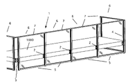
- FIG. 1 is a perspective view of the fascia-mounted aluminum railing system.
- FIG. 2 is a detail view of the fascia bracket, vertical post and bottom rail portions of the system.
- FIG. 3 is a detail view of a corner application.
- FIG. 4 is a detail view of the post-fascia bracket assembly.
- FIG. 5 is a cross-section of a fascia bracket extrusion.
- FIG. 6 is a cross-section of a splice extrusion member.
- FIG. 7 is a detail view of the second embodiment of the fascia bracket, vertical post and bottom rail portions of the system.
- FIG. 8 is a cross-section of a fascia bracket extrusion for the second embodiment of the fascia bracket.
- FIG. 1 a perspective view of the FMARS 1 is shown.
- this system is applied to an elevated slab 1000 .
- these slabs are reinforced concrete, however, the system can be utilized on other balcony materials, such as wood and steel.
- the key to this system is a series of fascia brackets 2 for straight runs and a special corner bracket 3 for the corners.
- the fascia brackets support a number of vertical posts 4 that are secured to the fascia brackets using splices (see below).
- the post can be one piece and are passed through the brackets and secured. This embodiment is discussed below.
- a bottom rail 5 is secured to the posts as shown.
- the posts and bottom rail form a frame in which infill panels 6 are placed.
- the infill options include tempered glass panels, pickets, and panels made of other materials such as expanded or perforated metals, composite materials or water jet panels (which are metal panels cut with a water jet to give a decorative appearance.) This construction is discussed in detail below.
- the panels are typically kept at the height of the posts and the system can be fitted with a top rail 7 . Of course, variations in this design are also possible.
- FIG. 2 is a detail view of the fascia bracket and bottom rail portions of the system.
- the fascia bracket is secured to the slab 1000 using conventional fasteners 8 suitable for the purpose.
- the shape of the fascia bracket is shown in FIG. 5 . It is designed to accommodate the vertical post sections as well as the infill panel.
- the vertical post 4 is actually made of two pieces. These are assembled using a splice, as discussed below. Sections of bottom rail 5 are attached to the posts. These provide a base for the infill panels 6 to sit. The infill panels are held in the posts using techniques common to the art.
- a bottom cap 10 is secured to the bottom of the lower post section to enclose the post and give the design a finished look.
- the infill panels are made of 1 ⁇ 4-inch or 3 ⁇ 8-inch-tempered glass.
- the lower portion of the panel, area 6 a can be tinted or coated to hide the slab edge.
- FIG. 3 is a detail view of a corner assembly. At the corners, a special fascia bracket 3 is used. These brackets have the same basic configuration as the regular fascia brackets. However, they are designed to accept a snap-in channel cover 11 to cover the open ends of the corner posts and brackets. Note that this figure also shows the top covers 12 . The top covers for the center posts have double indent to accommodate infill panels on both sides.
- This figure also shows a top rail 7 . Note also that the top rail 7 is joined by a miter joint at the corners, although this can vary depending on the desired design appearance.
- FIG. 4 is a detail view of the post-fascia bracket assembly for the first embodiment.
- the fascia bracket 2 is attached to the slab 1000 as discussed above. Because of the construction of the fascia bracket (see FIG. 5 ), the posts cannot pass into the fascia brackets 2 . Thus, to form the post and fascia assembly, the vertical post must be made of two pieces.
- FIG. 4 shows the upper portion 4 a of the post and the lower portion 4 b of the post aligned with the fascia bracket 2 .
- additional supports must be provided to hold the posts in place on top of and under the fascia bracket 2 . This is accomplished using two splice extrusion members 18 .
- the splice extrusion members 18 pass through the fascia brackets as shown. They are secured using epoxy and, if necessary, appropriate fasteners. As shown in FIG. 4 , the splice extrusion members 18 align with the extruded forms of the posts 4 a and 4 b . The post portions slide over the splice extrusion members until the post portions butt up against the fascia brackets. The post portions are then secured using epoxy and, if needed, appropriate fasteners.
- FIG. 5 is a cross-section of a fascia bracket extrusion for the first embodiment.
- the fascia brackets 2 have a pair of mounting flanges 20 that extends outward from the main body of the brackets.
- the main body has two open channels 21 that hold the splice extrusion members, as discussed above.
- a center web 22 joins the two channels 21 and provides a pair of channels for the infill panels. Note that the two open channels 21 have corner recesses 23 formed in them. These recesses receive the flanges on the splice extrusion members, as discussed below.
- FIG. 6 is a cross-section of a splice extrusion member 18 used in the first embodiment.
- the splice extrusion members had a shape that conforms to the shape of the open channels 21 of the fascia brackets. Note that the outer surfaces of the splice extrusion members have edges formed with gripping teeth 25 to help hold the splice extrusion members in the fascia brackets firmly in place.
- the splice extrusion members 18 also have corner flanges 26 that fit into the recesses 23 formed in the fascia brackets.
- FIG. 7 is a detail view of the second embodiment of the fascia bracket, vertical post and bottom rail portions of the system.
- no splices are used. Instead, a one-piece vertical post is slid down into the bracket until the desired position is reached. The post is then secured to the bracket using suitable fasteners in a mechanical connection.
- this embodiment is not as clean in appearance as the first embodiment, it is much simpler than the first embodiment and provides flexibility for field conditions.
- the new bracket 30 is shown with the single-piece post 31 passing through it. The bracket has side channels as before to hold the infill panels and bottom rail 5 .
- FIG. 8 is a cross-section of a fascia bracket extrusion for the second embodiment of the fascia bracket.
- This embodiment of fascia bracket 30 has a pair of mounting flanges 20 that extends outward from the main body of the brackets, as before.
- the main body has two open channels 21 and a center channel 21 a that one-piece post 31 (not shown).
- a center channel 21 a joins the two channels 21 to form a pair of channels 22 for the infill panels.
- the two open channels 21 have corner recesses 23 formed in them. These recesses receive flanges on the post members, which are similar to those formed on the splice members, as discussed above.
- To set the post the post is slid into the bracket until the flanges line up with the recesses 23 in the brackets. At this point, the post is set and can be secured in place.
Landscapes
- Engineering & Computer Science (AREA)
- Architecture (AREA)
- Civil Engineering (AREA)
- Structural Engineering (AREA)
- Bridges Or Land Bridges (AREA)
Abstract
Description
Claims (10)
Priority Applications (2)
| Application Number | Priority Date | Filing Date | Title |
|---|---|---|---|
| US11/504,955 US7497057B1 (en) | 2006-08-16 | 2006-08-16 | Fascia-mounted aluminum railing system |
| US12/286,400 US7617650B1 (en) | 2006-08-16 | 2008-09-30 | Fascia-mounted aluminum railing system |
Applications Claiming Priority (1)
| Application Number | Priority Date | Filing Date | Title |
|---|---|---|---|
| US11/504,955 US7497057B1 (en) | 2006-08-16 | 2006-08-16 | Fascia-mounted aluminum railing system |
Related Child Applications (1)
| Application Number | Title | Priority Date | Filing Date |
|---|---|---|---|
| US12/286,400 Division US7617650B1 (en) | 2006-08-16 | 2008-09-30 | Fascia-mounted aluminum railing system |
Publications (1)
| Publication Number | Publication Date |
|---|---|
| US7497057B1 true US7497057B1 (en) | 2009-03-03 |
Family
ID=40385299
Family Applications (2)
| Application Number | Title | Priority Date | Filing Date |
|---|---|---|---|
| US11/504,955 Expired - Fee Related US7497057B1 (en) | 2006-08-16 | 2006-08-16 | Fascia-mounted aluminum railing system |
| US12/286,400 Expired - Fee Related US7617650B1 (en) | 2006-08-16 | 2008-09-30 | Fascia-mounted aluminum railing system |
Family Applications After (1)
| Application Number | Title | Priority Date | Filing Date |
|---|---|---|---|
| US12/286,400 Expired - Fee Related US7617650B1 (en) | 2006-08-16 | 2008-09-30 | Fascia-mounted aluminum railing system |
Country Status (1)
| Country | Link |
|---|---|
| US (2) | US7497057B1 (en) |
Cited By (11)
| Publication number | Priority date | Publication date | Assignee | Title |
|---|---|---|---|---|
| US20090229202A1 (en) * | 2007-10-05 | 2009-09-17 | Norsk Hydro Asa | Half-shell for forming thermal break door and window frames or the like, associated section and associated assembly process |
| US20110017965A1 (en) * | 2009-07-23 | 2011-01-27 | Frank Kowalewicz | Fence and Rail Assemblies and Methods of Forming the Same |
| US20110099937A1 (en) * | 2006-08-02 | 2011-05-05 | Norsk Hydro Asa | Uninsulated section suitable for producing insulated sections for thermal break window and door frames and associated method of assembly |
| US8523149B1 (en) | 2011-11-18 | 2013-09-03 | Daryl Novak | Magnetic panels and locking clips |
| EP2677093A3 (en) * | 2012-06-19 | 2016-06-01 | Alutec Oy | Sealing arrangement for glazed balcony |
| EP3461967A1 (en) | 2017-09-28 | 2019-04-03 | C.R. Laurence Co., Inc. | Fascia mounted railing system |
| EP3436648A4 (en) * | 2016-03-30 | 2019-09-04 | Clephane, David Anthony | STRUCTURE BONDING SYSTEM |
| US11447956B1 (en) | 2019-02-11 | 2022-09-20 | Ufp Industries, Inc. | Glass panel railing securement |
| US11459816B2 (en) * | 2019-10-24 | 2022-10-04 | Av Builder Corp | Corner window lite assemblies |
| EP3880897A4 (en) * | 2018-11-14 | 2022-11-16 | Innovative Building Technologies, LLC | BALCONY SYSTEM AND METHOD |
| US12297076B2 (en) | 2018-11-14 | 2025-05-13 | Innovative Building Technologies, Llc | Modular stairwell and elevator shaft system and method |
Families Citing this family (2)
| Publication number | Priority date | Publication date | Assignee | Title |
|---|---|---|---|---|
| CA2770547C (en) | 2011-03-11 | 2013-06-11 | Marc-Andre Seguin | Curved safety component for a skating rink |
| FI124409B (en) * | 2013-04-02 | 2014-08-15 | Alutec Oy | Lower profile for balcony railings |
Citations (13)
| Publication number | Priority date | Publication date | Assignee | Title |
|---|---|---|---|---|
| US3251168A (en) * | 1961-12-28 | 1966-05-17 | Reynolds Metals Co | Exterior wall covering and support therefor |
| US3358969A (en) * | 1965-12-13 | 1967-12-19 | Blumcraft Pittsburgh | Ornamental railing |
| US3715848A (en) * | 1969-04-18 | 1973-02-13 | P Jordan | Multiple layer outside wall of a building or the like |
| US4956954A (en) * | 1989-03-17 | 1990-09-18 | Blumcraft Of Pittsburgh | Doorway system for glass doors and method of installation |
| US5771646A (en) * | 1997-06-05 | 1998-06-30 | Action Sales & Marketing Inc | Railing post reinforcement bracket |
| US5967498A (en) * | 1996-09-18 | 1999-10-19 | Junell; Jack S. | Modular fiberglass railing system |
| US6269600B1 (en) * | 1996-10-16 | 2001-08-07 | Stefanos Tambakakis | Curtain walls with suspended glassed panels |
| US6517056B2 (en) * | 2000-03-30 | 2003-02-11 | John D. Shepherd | Railing assembly |
| US6647562B1 (en) * | 2000-06-19 | 2003-11-18 | John Arout | Method for making portable, strong, light-weight and easily assembled containing structures using interlocking panel members |
| US6804920B2 (en) * | 2002-06-05 | 2004-10-19 | X-Clad, Inc. | Tube-lock curtain wall system |
| US6964410B1 (en) * | 2002-11-11 | 2005-11-15 | Hansen Tracy C | Suspended glass panel railing system |
| US7032891B2 (en) * | 2003-01-21 | 2006-04-25 | On The Fence Technologies, Llc Corporation | Methods and apparatus for fencing and other structures |
| US7127865B2 (en) * | 2002-10-11 | 2006-10-31 | Douglas Robert B | Modular structure for building panels and methods of making and using same |
Family Cites Families (3)
| Publication number | Priority date | Publication date | Assignee | Title |
|---|---|---|---|---|
| US7434790B1 (en) * | 2006-05-17 | 2008-10-14 | Hansen Tracy C | Vertical panel glass wall |
| US7530549B1 (en) * | 2007-01-29 | 2009-05-12 | Hansen Tracy C | Articulating balcony railing system |
| US7559536B1 (en) * | 2007-05-18 | 2009-07-14 | Hansen Tracy C | Structural glass railing base shoe design |
-
2006
- 2006-08-16 US US11/504,955 patent/US7497057B1/en not_active Expired - Fee Related
-
2008
- 2008-09-30 US US12/286,400 patent/US7617650B1/en not_active Expired - Fee Related
Patent Citations (13)
| Publication number | Priority date | Publication date | Assignee | Title |
|---|---|---|---|---|
| US3251168A (en) * | 1961-12-28 | 1966-05-17 | Reynolds Metals Co | Exterior wall covering and support therefor |
| US3358969A (en) * | 1965-12-13 | 1967-12-19 | Blumcraft Pittsburgh | Ornamental railing |
| US3715848A (en) * | 1969-04-18 | 1973-02-13 | P Jordan | Multiple layer outside wall of a building or the like |
| US4956954A (en) * | 1989-03-17 | 1990-09-18 | Blumcraft Of Pittsburgh | Doorway system for glass doors and method of installation |
| US5967498A (en) * | 1996-09-18 | 1999-10-19 | Junell; Jack S. | Modular fiberglass railing system |
| US6269600B1 (en) * | 1996-10-16 | 2001-08-07 | Stefanos Tambakakis | Curtain walls with suspended glassed panels |
| US5771646A (en) * | 1997-06-05 | 1998-06-30 | Action Sales & Marketing Inc | Railing post reinforcement bracket |
| US6517056B2 (en) * | 2000-03-30 | 2003-02-11 | John D. Shepherd | Railing assembly |
| US6647562B1 (en) * | 2000-06-19 | 2003-11-18 | John Arout | Method for making portable, strong, light-weight and easily assembled containing structures using interlocking panel members |
| US6804920B2 (en) * | 2002-06-05 | 2004-10-19 | X-Clad, Inc. | Tube-lock curtain wall system |
| US7127865B2 (en) * | 2002-10-11 | 2006-10-31 | Douglas Robert B | Modular structure for building panels and methods of making and using same |
| US6964410B1 (en) * | 2002-11-11 | 2005-11-15 | Hansen Tracy C | Suspended glass panel railing system |
| US7032891B2 (en) * | 2003-01-21 | 2006-04-25 | On The Fence Technologies, Llc Corporation | Methods and apparatus for fencing and other structures |
Cited By (16)
| Publication number | Priority date | Publication date | Assignee | Title |
|---|---|---|---|---|
| US20110099937A1 (en) * | 2006-08-02 | 2011-05-05 | Norsk Hydro Asa | Uninsulated section suitable for producing insulated sections for thermal break window and door frames and associated method of assembly |
| US20090229202A1 (en) * | 2007-10-05 | 2009-09-17 | Norsk Hydro Asa | Half-shell for forming thermal break door and window frames or the like, associated section and associated assembly process |
| US20110017965A1 (en) * | 2009-07-23 | 2011-01-27 | Frank Kowalewicz | Fence and Rail Assemblies and Methods of Forming the Same |
| US8523149B1 (en) | 2011-11-18 | 2013-09-03 | Daryl Novak | Magnetic panels and locking clips |
| US8806736B1 (en) | 2011-11-18 | 2014-08-19 | Daryl Novak | Magnetic panels and locking clips |
| EP2677093A3 (en) * | 2012-06-19 | 2016-06-01 | Alutec Oy | Sealing arrangement for glazed balcony |
| EP3436648A4 (en) * | 2016-03-30 | 2019-09-04 | Clephane, David Anthony | STRUCTURE BONDING SYSTEM |
| AU2018236795B2 (en) * | 2017-09-28 | 2019-10-17 | C.R. Laurence Co., Inc. | Fascia mounted railing system |
| EP3461967A1 (en) | 2017-09-28 | 2019-04-03 | C.R. Laurence Co., Inc. | Fascia mounted railing system |
| US10767372B1 (en) * | 2017-09-28 | 2020-09-08 | C.R. Laurence Co., Inc. | Fascia mounted railing system |
| EP3880897A4 (en) * | 2018-11-14 | 2022-11-16 | Innovative Building Technologies, LLC | BALCONY SYSTEM AND METHOD |
| US12297076B2 (en) | 2018-11-14 | 2025-05-13 | Innovative Building Technologies, Llc | Modular stairwell and elevator shaft system and method |
| US11447956B1 (en) | 2019-02-11 | 2022-09-20 | Ufp Industries, Inc. | Glass panel railing securement |
| US11459816B2 (en) * | 2019-10-24 | 2022-10-04 | Av Builder Corp | Corner window lite assemblies |
| US12031377B2 (en) | 2019-10-24 | 2024-07-09 | Av Builder Corp | Corner window lite assemblies |
| US12540504B2 (en) | 2019-10-24 | 2026-02-03 | Av Builder Corp | Corner window lite assemblies |
Also Published As
| Publication number | Publication date |
|---|---|
| US7617650B1 (en) | 2009-11-17 |
Similar Documents
| Publication | Publication Date | Title |
|---|---|---|
| US7617650B1 (en) | Fascia-mounted aluminum railing system | |
| US6964410B1 (en) | Suspended glass panel railing system | |
| US6668495B1 (en) | Variable load capacity and aesthetically enhanced construction components for patio enclosures | |
| US6601362B1 (en) | Variable load capacity construction components for patio pool enclosures | |
| US20100058691A1 (en) | Cellular pvc siding, trim, and architectural assemblies | |
| US20090134377A1 (en) | Railing system | |
| US20200362566A1 (en) | Fascia Mounted Railing System | |
| US20070039257A1 (en) | Low profile architectural detailing assembly | |
| US11441318B2 (en) | Modular staircase and method of constructing same | |
| US11180921B2 (en) | Hidden fastener railing system | |
| US7530549B1 (en) | Articulating balcony railing system | |
| US20050191466A1 (en) | Laminate structural material trim and applications thereof | |
| EP0808404B1 (en) | Mounting assembly for a sheet-like piece, particularly a balcony glazing | |
| CA2552213C (en) | Hidden fastener guard rail system | |
| JP3031266B2 (en) | Fence structure | |
| JP3698695B2 (en) | Handrail | |
| KR20090053038A (en) | Handrail structure with glass plate | |
| US20020152713A1 (en) | Baluster | |
| KR20210136337A (en) | Ceiling panel installation structure | |
| EP4226000B1 (en) | Support system for railings of existing or newly built balconies | |
| KR102362861B1 (en) | Guardrail assembly | |
| JP7323415B2 (en) | entrance porch | |
| WO2012142660A1 (en) | Panel support member | |
| JP2003313955A (en) | Unit building | |
| JP3074476U (en) | Fence |
Legal Events
| Date | Code | Title | Description |
|---|---|---|---|
| STCF | Information on status: patent grant |
Free format text: PATENTED CASE |
|
| REMI | Maintenance fee reminder mailed | ||
| FPAY | Fee payment |
Year of fee payment: 4 |
|
| SULP | Surcharge for late payment | ||
| FPAY | Fee payment |
Year of fee payment: 8 |
|
| SULP | Surcharge for late payment |
Year of fee payment: 7 |
|
| FEPP | Fee payment procedure |
Free format text: MAINTENANCE FEE REMINDER MAILED (ORIGINAL EVENT CODE: REM.); ENTITY STATUS OF PATENT OWNER: SMALL ENTITY |
|
| LAPS | Lapse for failure to pay maintenance fees |
Free format text: PATENT EXPIRED FOR FAILURE TO PAY MAINTENANCE FEES (ORIGINAL EVENT CODE: EXP.); ENTITY STATUS OF PATENT OWNER: SMALL ENTITY |
|
| STCH | Information on status: patent discontinuation |
Free format text: PATENT EXPIRED DUE TO NONPAYMENT OF MAINTENANCE FEES UNDER 37 CFR 1.362 |
|
| FP | Lapsed due to failure to pay maintenance fee |
Effective date: 20210303 |