US7489720B2 - Method for transmit pulse design for ultra-wideband communications - Google Patents
Method for transmit pulse design for ultra-wideband communications Download PDFInfo
- Publication number
- US7489720B2 US7489720B2 US10/700,723 US70072303A US7489720B2 US 7489720 B2 US7489720 B2 US 7489720B2 US 70072303 A US70072303 A US 70072303A US 7489720 B2 US7489720 B2 US 7489720B2
- Authority
- US
- United States
- Prior art keywords
- pulse
- spectral mask
- interferers
- signal
- representation
- Prior art date
- Legal status (The legal status is an assumption and is not a legal conclusion. Google has not performed a legal analysis and makes no representation as to the accuracy of the status listed.)
- Active, expires
Links
Images


Classifications
-
- H—ELECTRICITY
- H04—ELECTRIC COMMUNICATION TECHNIQUE
- H04B—TRANSMISSION
- H04B1/00—Details of transmission systems, not covered by a single one of groups H04B3/00 - H04B13/00; Details of transmission systems not characterised by the medium used for transmission
- H04B1/69—Spread spectrum techniques
- H04B1/7163—Spread spectrum techniques using impulse radio
- H04B1/719—Interference-related aspects
-
- H—ELECTRICITY
- H04—ELECTRIC COMMUNICATION TECHNIQUE
- H04B—TRANSMISSION
- H04B1/00—Details of transmission systems, not covered by a single one of groups H04B3/00 - H04B13/00; Details of transmission systems not characterised by the medium used for transmission
- H04B1/69—Spread spectrum techniques
- H04B1/7163—Spread spectrum techniques using impulse radio
- H04B1/717—Pulse-related aspects
- H04B1/7172—Pulse shape
Definitions
- the present invention relates generally to a method for wireless communications, and more particularly to methods for designing and transmitting transmit pulses for ultra- wideband communications systems.
- Ultra-wideband (UWB) communications systems are normally defined as carrier-less communications systems wherein the bandwidth of the signal being transmitted, f B , is greater than or equal to 0.20 f c , where f c is the center frequency of the signal being transmitted. Additionally, the UWB communications system should have a minimum bandwidth of 500 MHz. Note that the definition for UWB communications systems and devices is as defined by the Federal Communications Commission (FCC) of the United States.
- FCC Federal Communications Commission
- UWB communications systems have been around for a great number of years, and the majority of them fall under a single type of system, they modulate a stream of short-duration pulses (with an approximate duration which ranges from 0.2 nanoseconds (ns) to 2 ns), either in time (pulse position modulation (PPM)), amplitude (pulse amplitude modulation (PAM)), or phase angle (bi-phase modulation).
- PPM pulse position modulation
- PAM pulse amplitude modulation
- phase angle bi-phase modulation
- the FCC in Report Order 02-48 released in February of 2002, has specified a set of spectral allocation, technical standards, and operating restrictions for several different types of UWB devices. For example, in the Report Order, the FCC specifies that indoor UWB devices may operate within a frequency range of 1.9 to 10.6 GHz while hand-held UWB devices may operate within a frequency range of 3.1 to 10.6 GHz. Within the permitted frequency ranges, the FCC also places a limit upon maximum transmit power.
- a commonly used signal in UWB is known as the ‘chirp.’
- Two different implementations of the chirp signal have been disclosed in previous patents. A first is called the Gaussian weighted sinusoidal function and the second is called the inverse-exponentially weighted sinusoidal function.
- the two versions of the chirp signal offer a good approximation of the rectangular shaped signal in the frequency domain, and therefore, are good candidates for use in a UWB system.
- One disadvantage of the prior art is that there are signal components of the chirp signals exist at every frequency within the transmit frequency band. Therefore, if there are wireless communications systems operating within the general vicinity of the UWB system, the transmission of the chirp signals could pose interference problems. Furthermore, the transmissions from the wireless communications systems can also interfere with the communications of the UWB system.
- a second disadvantage of the prior art is that in order to provide a good approximation of the rectangular shape, a relatively large number of taps may be needed. The large number of taps can make it difficult to actually implement the pulse in a UWB system.
- a method for forming a quantized representation of a pulse comprising specifying a spectral mask for the pulse, applying an optimization routine to compute samples of the quantized representation of the pulse, wherein the optimization routine minimizes a difference between the quantized representation of the quantized representation and the pulse, and storing the samples of the quantized representation of the pulse is provided.
- a method for transmitting a pulse to mitigate interference comprising determining the presence of interferers, specifying a spectral mask for the pulse, wherein the spectral mask is used to describe a frequency response of the pulse, and wherein if the interferers occupy a portion of the spectral mask intended to carry signal, then portions of the spectral mask corresponding to frequencies of the interferers are set to carry significantly less signal than portions corresponding to frequencies intended to carry signal, computing the pulse based on the spectral mask, and providing the pulse to an antenna is provided.
- a method of transmitting a pulse comprising creating a representation of a sample of the pulse based upon information about the sample, wherein the pulse has a variation of more than a specified value across its pass band, providing the representation to an antenna to transmit the representation of the sample, and repeating the creating and providing until all samples of the pulse have been transmitted is provided.
- An advantage of a preferred embodiment of the present invention is that a good approximation of the rectangular shaped signal in the frequency domain can be achieved with a relatively small number of taps. This can allow for simple and inexpensive implementations of a UWB communications system.
- a further advantage of a preferred embodiment of the present invention is that in the presence of interferers, portions of the transmit frequency band can be eliminated. This can reduce the UWB system's interference to other wireless communications systems.
- Yet another advantage of a preferred embodiment of the present invention is that by not transmitting data in portions of the frequency band where interference is occurring, the UWB system can actually perform better, since transmitted data is not being damaged and possibly requiring retransmissions.
- FIG. 1 is a diagram of an exemplary ultra-wideband (UWB) wireless communications system
- FIG. 2 is a diagram of a spectral mask for an indoor UWB system
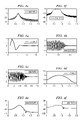
- FIGS. 3 a through 3 f are time and frequency domain plots for exemplary Gaussian weighted sinusoidal signals
- FIGS. 4 a through 4 f are time and frequency domain plots for exemplary inverse-exponentially weighted sinusoidal signals
- FIG. 5 is a diagram of a process for pulse design using filter design techniques, according to a preferred embodiment of the present invention.
- FIGS. 6 a through 6 f are time and frequency domain plots of signals approximating the perfect rectangle signal created using the least squares optimization technique, according to a preferred embodiment of the present invention.
- FIG. 7 is a data plot of signal energy versus signal length, according to a preferred embodiment of the present invention.
- FIG. 8 is a diagram of a spectral mask with an interferer
- FIG. 9 is a data plot of a frequency response of a pulse for a UWB system wherein there is no transmit energy within a specified frequency band, according to a preferred embodiment of the present invention.
- FIG. 10 is a diagram of a process for pulse design using filter design techniques, wherein portions of the frequency response of the pulse can be modified in response to interferers, according to a preferred embodiment of the present invention
- FIG. 11 is a diagram of a circuit to generate a quantized representation of an analog pulse, according to a preferred embodiment of the present invention.
- FIG. 12 is a diagram of an implementation of the circuit 1100 used to generate a quantized representation of an analog pulse, according to a preferred embodiment of the present invention.
- FIG. 13 is a diagram of a process for generating and transmitting a quantized representation of an analog pulse, according to a preferred embodiment of the present invention.
- FIG. 14 is a high level block diagram of a UWB transmitter with a configurable pulse generator, according to a preferred embodiment of the present invention.
- the present invention will be described with respect to preferred embodiments in a specific context, namely a UWB communications system operating within FCC specified regulations.
- the FCC specified rules can be found in a Report Order entitled “Revision of Part 15 of the Commission's Rules Regarding Ultra-Wideband Transmission Systems,” released Apr. 22, 2002, which is herein incorporated by reference.
- the invention may also be applied, however, to other UWB communications systems operating within other portions of the world, wherein the FCC's regulations do not apply.
- the invention may be applied to UWB communications systems that use only any portion of the allowed spectrum, not just all of it.
- the invention can have application to non-UWB communications systems that may have a need for a pulse with a certain bandwidth which has a need for certain portions of the bandwidth notched out.
- the UWB wireless communications system as displayed includes a UWB transmitter 105 and a UWB receiver 110 .
- the UWB transmitter 105 may use an antenna 106 in its transmitting, while the UWB receiver 110 may use an antenna 111 to receive the transmitted signals.
- the UWB wireless communications system is illustrated with a single receiver and a single transmitter, there can be and typically are more than one receiver and one transmitter in a wireless communications system.
- UWB communications systems use streams of short duration pulses to encode and transmit data, although in the strictest sense, any wireless communications system is classified as an UWB communications system if the bandwidth of the signal being transmitted, f B , is greater than or equal to 0.20 f c , where f c is the center frequency of the signal being transmitted. Additionally, the UWB communications system should have a minimum bandwidth of 500 MHz. Therefore, other data encoding and transmission methodologies can be employed by UWB communications systems.
- FIG. 2 there is shown a diagram illustrating a spectral mask 200 for an indoor UWB system.
- a UWB system that is to be used in an indoor application must make sure that its transmissions fall within the spectral mask 200 .
- the UWB system For a frequency band between 960 to 1610 MHz, the UWB system must transmit at a power level of less than ⁇ 75.3 dBm (shown in FIG. 2 as block 205 ).
- the transmit power level For a frequency band between 1610 to 1990 MHz, the transmit power level must be less than ⁇ 53.3 dBm (block 210 ).
- the transmit power level needs to be less than ⁇ 51.3 dBm (block 215 ), while the transmit power is limited to being less than ⁇ 41.3 dBm within a frequency band from 3100 to 10600 MHz (block 220 ). Finally, for frequencies above 10600 MHz, the transmit power is required to be less than ⁇ 51.3 dBm (block 225 ). Note that in portions of the spectral mask where no signal is to be transmitted, the spectral mask can take on essentially zero values (large negative values when represented in dBm).
- FIG. 2 illustrates a spectral mask for an indoor UWB system.
- the FCC specifies spectral masks for other types of UWB systems, such as hand-held UWB systems, vehicular radar UWB systems, and UWB imaging systems.
- Each type of UWB system has a different spectral mask that is intended to help prevent the system from causing undue interference to existing systems.
- other countries and regions of the world may have other restrictions on UWB systems. Therefore, although the discussion of the present invention focuses upon a UWB system operating under FCC regulations, it should be understood that these limitations should not be a limiting factor upon the present invention.
- FIGS. 3 a through 3 f there are shown diagrams illustrating time and frequency domain plots of exemplary Gaussian weighted sinusoidal signals.
- FIGS. 3 a through 3 c illustrate time domain plots of exemplary Gaussian weighted sinusoidal signals with 16, 64, and 256 taps respectively.
- FIGS. 3 d through 3 f illustrate frequency domain plots of the same exemplary Gaussian weighted sinusoidal signals in FIGS. 3 a through 3 c . Note that as the number of taps (samples) increase, the frequency response of the Gaussian weighted sinusoidal signals approach that of the desired rectangular pulse.
- FIGS. 4 a through 4 f there are shown diagrams illustrating time and frequency domain plots of exemplary inverse-exponentially weighted sinusoidal signals.
- FIGS. 4 a through 4 c illustrate time domain plots of exemplary inverse-exponentially weighted sinusoidal signals with 16, 64, and 256 taps respectively.
- FIGS. 4 d through 4 f illustrate frequency domain plots of the same exemplary inverse-exponentially weighted sinusoidal signals in FIGS. 4 a through 4 c .
- FIG. 5 there is shown a diagram illustrating a process 500 for pulse design using filter design techniques, according to a preferred embodiment of the present invention.
- a pulse's frequency domain characteristics can be specified and then, using filter design techniques, a time domain signal with frequency domain characteristics similar to the specified characteristics can be created.
- a set of frequency domain characteristics for the pulse should be specified (block 505 ).
- the set of frequency domain characteristics can include portions of the frequency spectra where there should be no signal components (this can correspond to the filter's stop band(s)) and portions of the frequency spectra where there should be signal components (this may correspond to the filter's pass band(s)).
- the stop band and pass bands specified may not go completely to the edges of the frequency bands as specified by the FCC. This may be due to the presence of a transition band between the pass and stop bands of a filter. Additionally, by stopping short of the edges, the frequency spectra of the pulse can be ensured of meeting FCC regulations.
- an ideal signal to represent the frequency domain characteristics of the pulse would be a perfect rectangle, H i ( ⁇ ) .
- a perfect rectangle in the frequency domain would be an infinite length filter in the time domain, therefore, making it impossible to implement.
- a finite length approximation can be used.
- An equation for an N+1 tap (sample) signal can be expressed as:
- An optimization technique can now be applied to minimize the difference between the infinite length ideal signal, the perfect rectangle, H i ( ⁇ ), and the finite length (N+1 tap) filter, H( ⁇ ) (block 510 ).
- Many different optimization techniques can be used, such as the least squares techniques, weighted least squares techniques, minimum mean square techniques, constrained optimization techniques, generalized Remez algorithm, and so on.
- the least squares and minimum mean square techniques for optimization are considered to be well known by those of ordinary skill in the art of the present invention.
- the use of the least squares technique to optimize H( ⁇ ) is presented below.
- e T e should be equal to zero and be perpendicular to W ⁇ right arrow over (a) ⁇ i .
- a table below displays the specifications for several pulses with variation in the number of taps, weighting functions, and sets of frequency domain characteristics.
- Stopband1 Passband Stopband2 # Taps (MHz) (MHz) (MHz) W S1 W P W S2 16 ⁇ 3600 3600-10150 >10150 10 1 10 33 ⁇ 3600 3600-10150 >10150 3 1 3 65 ⁇ 3350 3350-10350 >10350 2 1 2 129 ⁇ 3300 3300-10350 >10350 2 1 2 257 ⁇ 3300 3300-10400 >10400 1 1 1 513 ⁇ 3100 3100-10600 >10600 1 1 1 1025 ⁇ 3100 3100-10600 >10600 1 1 1 1 Note that for larger number of taps, the values of the weighting functions in the stop bands can be decreased to provide the optimization technique greater freedom. When there is a small number of taps, the values of the weighting functions in the stop bands can be large to place greater emphasis on the optimization of the stop bands (to ensure that there are no frequency components in the prohibited frequency bands).
- the taps of the filter can be stored for later use (block 515 ).
- the filter taps can be stored in coefficient form in a memory or a look-up table.
- the filter taps can be stored as a sequence of control and timing signals for a circuit that can be used to create the pulse. For example, if a multi-switch circuit is to be used to create the pulse, then each filter tap can be stored as a combination of switch settings required to create the particular filter tap. Additionally, further pieces of information such as information regarding the duration of time to hold each switch setting can be stored with the switch settings.
- FIGS. 6 a through 6 f there are shown diagrams illustrating time and frequency domain plots of signals approximating the perfect rectangle signal created using the least squares optimization technique, according to a preferred embodiment of the present invention.
- FIGS. 6 a through 6 c illustrate time domain plots of the approximations of the perfect rectangle signals with 16, 64, and 256 taps respectively.
- FIGS. 6 d through 6 f illustrate frequency domain plots of the same approximations of the perfect rectangle shown in FIGS. 6 a through 6 c . Note that as the number of taps (samples) increase, the frequency response of the approximations approaches that of the desired perfect rectangular signal.
- a first curve 705 displays the energy present in the perfect rectangle signal. Since the perfect rectangle is an ideal signal with infinite length, the number of taps does not apply and has no effect upon the energy.
- a second curve 710 displays the energy present in a signal created using the least squares optimization of the approximation to the perfect rectangle signal. The second curve 710 shows that even for a small number of taps, the approximation signal has an energy that can come close to the energy present in the perfect rectangle signal and that for a large number of taps, the approximation signal has an energy that can approach that of the perfect rectangle signal.
- a third curve 715 displays the energy present in a Gaussian weighted sinusoidal signal while a fourth curve 720 displays the energy present in an inverse-exponentially weighted sinusoidal signal.
- the energy levels present in the Gaussian weighted sinusoidal signal (the third curve 715 ) and the inverse-exponentially weighted sinusoidal signal (the fourth curve 720 ) does not come close to approaching the energy in the perfect rectangle signal, even for large values of the number of taps.
- the Gaussian weighted sinusoidal signal and the inverse-exponentially weighted sinusoidal signal are not good approximations of the perfect rectangle.
- wireless communications devices may receive interference from other electronic and electrical devices operating nearby. Furthermore, the wireless communications devices may be a source of undesired interference to existing electronic devices operating nearby. For example, within the permitted frequency band of UWB systems is the Unlicensed National Information Infrastructure (UNII) band (from 5.15 to 5.825 GHz). Devices operating within the UNII band have no restriction upon use (besides maximum transmit power) with the exception that they do not cause interference upon other devices operating within the same band and that they are capable of operating in the presence of interference from other devices. An example of devices that operate within the UNII band would be the class of communications devices that are compliant to the IEEE 802.11a technical specifications.
- UNII Unlicensed National Information Infrastructure
- FIG. 8 there is shown a diagram illustrating a spectral mask of a UWB communications system with an interferer.
- an interferer shown as shaded block 805
- the UWB transmission band can be significantly larger than that of a device operating in the UNII band, transmissions from the UNII device can have an impact on the UWB device and vice versa. Therefore, to eliminate interference to the UNII device (and to mitigate interference from the UNII device), the UWB device may elect to not transmit any signal within the UNII band portion of its transmit spectrum.
- FIG. 9 illustrates a frequency response of a transmit pulse, such as an approximation of the perfect rectangle created using the optimization technique discussed above.
- the frequency response of the transmitted pulse has a stop band 905 on either side of a transmit band 910 , wherein the transmit band 910 is where the signal being transmitted is carried.
- there may be a second stop band 915 which can effectively split the transmit band 910 into a first transmit band 917 and a second transmit band 919 .
- the second stop band 915 may have been intentionally created to prevent the UWB system from causing interference with and receiving interference from existing electronic devices operating within the general vicinity of the UWB system, such as other wireless communications systems, and so forth.
- the magnitude of the second stop band 915 can be dependent upon the type and magnitude of the interferer. For example, if the interferer is large, then the magnitude of the second stop band 915 should also be large to remove the large interferer. If the interferer is relatively small, then the second stop band 915 does not need to be as large.
- the present invention can support the exclusion of more than one frequency band. For example, if there are three frequency bands that a UWB system wishes to exclude from its transmission, then it can be possible for three stop bands to be placed into the frequency response of the approximation of the perfect rectangle.
- FIG. 10 there is shown a diagram illustrating a process 1000 for pulse design using filter design techniques, wherein portions of the frequency response of the pulse can be modified in response to interferers, according to a preferred embodiment of the present invention.
- the pulse design process 1000 can be similar to the pulse design process 500 ( FIG. 5 ) with additional support for modifying the frequency response of the pulse being designed to accommodate the presence of interference from electrical and electronic devices operating nearby.
- interferers can be determined (block 1005 ).
- interferers can be determined by scanning the transmission band of the UWB system. Then, any interferers detected can be used in the specification of the spectra of the pulse (block 1010 ). The scanning for interferers can occur during a power-up sequence for the UWB system. Alternatively, the scanning can occur periodically during the operation of the UWB system or when the performance of the UWB system degrades below a specified threshold.
- interferers can be detected based on a combination of received signal strength indicator (RSSI) and packet error rate (PER) measurements.
- RSSI received signal strength indicator
- PER packet error rate
- a user of the UWB system can enter known sources of interference (such as other wireless communications systems) operating in close proximity to the UWB system during the configuration of the UWB system.
- an optimization technique such as the least squares optimization discussed previously, can be applied (block 1015 ).
- the results of the pulse design can be stored for later use (block 1020 ).
- circuit 1100 to generate a quantized representation of an analog pulse, wherein the circuit 1100 produces a differential mode output, according to a preferred embodiment of the present invention.
- the circuit 1100 can be changed to produce a single ended output by persons of ordinary skill in the art of the present invention without requiring a significant amount of changes to the circuit 1100 or effort.
- UWB Ultra-Wideband
- a pair of amplifier blocks 1105 can be used to produce a differential output signal based upon control signals produced by an amplifier control 1110 .
- the amplifier control 1110 may make use of information needed to recreate the analog pulse which was stored in a memory (not shown).
- the information stored in the memory about the analog signal may have been created using the pulse design process 500 ( FIG. 5 ) or 1000 ( FIG. 11 ) as discussed above.
- the stored information may be actual samples of the analog pulse or it may be amplifier block setting information that can be used to create a sample of the analog pulse.
- the amplifier control 1110 may also retrieve timing information from the memory. The timing information may tell the amplifier control 1110 how long to maintain the current sample, for example.
- the information used in the recreation quantized version of the analog pulse may be pre-programmed into the circuit 1100 , such as in the pair of amplifier blocks 1105 or in the amplifier control 1110 .
- Output from the pair of amplifier blocks 1105 may then be provided to a switching unit 1115 .
- the switching unit 1115 can be controlled by polarity data which can also be provided by the amplifier control 1110 or retrieved directly from the memory or pre-programmed.
- the switching unit 1115 can be used to switch the positive output and the negative output to produce an output of opposite polarity.
- the amplifier control 1110 may retrieve information about the quantized version of the analog pulse from where the information is stored (perhaps a sample at a time or an entire group of samples corresponding to the quantized analog pulse) and then, a sample at a time, the amplifier control 1110 can produce control signals to provide to the pair of amplifier blocks 1105 .
- the pair of amplifier blocks 1105 based upon the control signals provided by the amplifier control 1110 , could then produce a differential mode output signal corresponding to the sample. After having the pair of amplifier blocks 1105 maintain the differential mode output signal for a period of time corresponding to the sampling period of the quantized signal, the amplifier control 1110 can generate control signals for the next sample.
- a high speed digital-to-analog converter can be used to perform the conversion of sample information to the quantized representation of the analog pulse.
- the DAC would need to be able to operate at a sufficiently high frequency so that it can generate the quantized representation of the analog pulse at the desired rate.
- the DAC may be provided the sample information (one at a time) and it would convert the sample information into a voltage representation which could then be provided to transmit circuitry.
- FIG. 12 there is shown a diagram illustrating an implementation of the circuit 1100 used to generate a quantized representation of an analog pulse, according to a preferred embodiment of the present invention.
- the amplifier blocks 1105 may be implemented using a single design, with the exception of the values of the power rails. Therefore, the discussion of a single amplifier block will sufficiently describe both amplifier blocks 1105 .
- the amplifier block 1105 features four amplifiers 1205 , 1206 , 1207 , and 1208 .
- the number of amplifiers in the amplifier block 1105 can be a function of the number of quantization bits used to represent the analog pulse. For example, if there are three quantization bits, then four amplifiers may be needed to represent four different quantization levels (the third quantization bit may be used to represent the sign of the analog pulse (the polarity data) and can be used to control the switching unit 1115 ( FIG. 11 )). If there are four quantization bits, then eight amplifiers may be needed.
- each of the four amplifiers 1205 , 1206 , 1207 , and 1208 is identical to one another, producing essentially the same amount of current (or as closely equal as possible per manufacturing methods used to create the amplifiers).
- the use of identical currents in each of the amplifiers implements what is commonly referred to as thermometer scaling.
- All four amplifiers 1205 , 1206 , 1207 , and 1208 are connected together at one end to a power rail, for example, Vdd.
- Each of the four amplifiers is also connected to a switch 1210 , 1211 , 1212 , and 1213 (for example, amplifier 1205 is connected to a switch 1210 ).
- Each of the four switches ( 1210 , 1211 , 1212 , and 1213 ) is controlled by a control signal, ⁇ , produced by the amplifier control 1110 .
- switch 1210 is controlled by control signal ⁇ 4
- switch 1211 is controlled by control signal ⁇ 3 , etc.
- the control signals selectively couple and decouple their respective amplifiers to a current path that includes a resistor 1215 .
- the voltage drop across the resistor 1215 and the corresponding voltage drop across a similar resistor (shown, but not labeled) in the second amplifier block 1105 are provided to a pair of multiplexers 1220 .
- the multiplexers 1220 are used to selectively couple the outputs of the pair of amplifier blocks 1105 to the output of the circuit 1100 .
- the multiplexers 1220 may be controlled by the polarity data (for example, the first bit of the three-bit digital representation of the signal (the polarity bit)), which selectively selects one of two inputs of each of the two multiplexers 1220 and produces them at the output of the circuit 1100 . Note that since the circuit 1100 generates a differential output, the actual output signal is carried on two signal lines.
- FIG. 13 there is shown a diagram illustrating a process 1300 for generating and transmitting a quantized representation of an analog pulse, according to a preferred embodiment of the present invention.
- the process 1300 illustrates the generation and transmission of a quantized version of an analog pulse using circuitry such as the circuit 1100 ( FIG. 11 ).
- the process 1300 can begin with the retrieval of information about a sample (or samples) of the quantized representation of the analog pulse (block 1305 ).
- the information may be stored in a memory (not shown) or some other storage device in a transmitter.
- the quantized representation of the analog pulse requires very high frequency pulse, wherein the frequency may be greater than a frequency supportable by reading samples from a memory
- the information needed to generate the samples may be pre-programmed into the circuitry used to generate the quantized representation of the analog pulse.
- the pre-programmed circuitry may be a part of the pair of amplifier blocks 1105 ( FIG. 11 ) or the amplifier control 1110 ( FIG. 11 ) or both.
- the circuitry can generate a voltage drop corresponding to the sample of the quantized representation of the analog pulse (block 1310 ). Alternatively, the circuitry may generate a current corresponding to the sample. The voltage drop can then be provided to an antenna to be transmitted (block 1315 ). After the voltage drop has been provided to the antenna, a check can be made to determine if the entire analog pulse has been transmitted (block 1320 ). If the entire analog pulse has not been transmitted, then the process 1300 can be repeated to generate and transmit the next sample of the quantized representation of the analog pulse.
- the UWB transmitter 1400 is a fairly typical UWB transmitter in that it can be divided into two major portions, a digital portion 1405 and an analog portion 1430 , plus an antenna 1445 .
- the digital portion 1405 is responsible for functions such as scrambling the serial data stream (for example, a scrambler 1420 ), converting the encoded information stream into a serial data stream (for example, a parallel-to-serial converter 1415 ), encoding (for example, a convolutional encoder 1410 ) a stream of information bits that is provided to the UWB transmitter 1400 by some information generator, such as a digital device or a user, etc., and spreading the scrambled serial data stream (for example, a spreading unit 1425 ).
- the digital portion 1405 of the UWB transmitter 1400 is responsible for converting the information bits into a form that is ready for transmission.
- the analog portion 1430 receives the spread and scrambled serial data stream from the digital portion 1405 and then uses it to modulate the stream of short duration pulses.
- the analog portion 1430 includes the configurable pulse generator 1435 , which is responsible for generating a generic pulse that is then modulated depending upon the value of a data bit (or chip) from the spread and scrambled serial data stream.
- the configurable pulse generator 1435 has as input, a clock 1437 (or an oscillator). After being modulated, the stream of short duration pulses is filtered by a filter unit 1440 .
- the filter unit 1440 ensures that the transmission of the UWB transmitter 1400 conforms to any physical and regulatory restrictions placed upon the output of the UWB transmitter 1400 .
- the filtered stream of short duration pulses is provided to the antenna 1445 where it is transmitted over-the-air. Due to the large bandwidth of the UWB transmitter 1400 , it is preferred that the antenna 1445 be an ultra-wideband antenna, i.e., the antenna 1445 has a bandwidth compatible with that of the bandwidth of the signal transmitted by the UWB transmitter 1400 .
Landscapes
- Engineering & Computer Science (AREA)
- Computer Networks & Wireless Communication (AREA)
- Signal Processing (AREA)
- Transmitters (AREA)
Abstract
Description
H(ω)=A(ω)e j(θ
wherein A(ω) is a real amplitude function and H(ω) has linear phase. A further simplification shows that H(ω) can be written as the sum of cosine terms:
H(ω)=e −jωN/2[(h 0 +h N)cos(ωN/2)+j(h 0 −h N)sin(ωN/2)+ . . . +(h N/2−1 +h N/2+1)cos(ω(N/2−1))+j(h N/2−1 −h N/2+1)sin(ω(N/2−1))] (3)
By observation, θ1=0 and θ2=N/2. Solving for A(ω) gives:
Perhaps to better attain the desired frequency response, a weighting function, W(ωk), can more heavily weight the error in certain areas of the frequency spectra as to make those areas more closely approximate the perfect rectangle. The error function can then be expressed as:
Through the use of Parseval's Theorem which states that the energy of a signal in the time domain is equal to the energy of that signal in the frequency domain, the above error function can be simplified to:
Note that the terms of h[n] that are outside of the N terms centered about the origin may be equal to zero, so the square of the terms of the perfect rectangle for L−1>|n|>N/2 just adds to the error measurement. The error function can further simplify to:
In order to find a closed form solution for minimizing the error for a given weighting function, the equation for A(ω) (equation 4) can be rewritten in matrix algebra:
F{right arrow over (h)}=W{right arrow over (a)}, (9)
wherein {right arrow over (h)} is an N/2 length vector (since the signal is real and has linear phase, only one half of the taps need to be solved for), F is a L×(N/2) matrix where Fij=cos(ωi(N/2−mj)), W is a L×L matrix and {right arrow over (a)} is a length L vector of frequency samples of the real valued amplitude function A(ω).
Fh=W{right arrow over (a)} i +{right arrow over (e)}. (10)
In order to minimize the squared error, eTe should be equal to zero and be perpendicular to W{right arrow over (a)}i. By multiplying the above equation (equation 10) through by eT, it is clear that eTF, or equivalently, FTe should be equal to the zero vector. Multiplying
{right arrow over (h)}=(F T WF)−1 F T W{right arrow over (a)} i. (11)
| Stopband1 | Passband | Stopband2 | ||||
| # Taps | (MHz) | (MHz) | (MHz) | WS1 | WP | WS2 |
| 16 | <3600 | 3600-10150 | >10150 | 10 | 1 | 10 |
| 33 | <3600 | 3600-10150 | >10150 | 3 | 1 | 3 |
| 65 | <3350 | 3350-10350 | >10350 | 2 | 1 | 2 |
| 129 | <3300 | 3300-10350 | >10350 | 2 | 1 | 2 |
| 257 | <3300 | 3300-10400 | >10400 | 1 | 1 | 1 |
| 513 | <3100 | 3100-10600 | >10600 | 1 | 1 | 1 |
| 1025 | <3100 | 3100-10600 | >10600 | 1 | 1 | 1 |
Note that for larger number of taps, the values of the weighting functions in the stop bands can be decreased to provide the optimization technique greater freedom. When there is a small number of taps, the values of the weighting functions in the stop bands can be large to place greater emphasis on the optimization of the stop bands (to ensure that there are no frequency components in the prohibited frequency bands).
Claims (41)
Priority Applications (1)
| Application Number | Priority Date | Filing Date | Title |
|---|---|---|---|
| US10/700,723 US7489720B2 (en) | 2002-11-04 | 2003-11-04 | Method for transmit pulse design for ultra-wideband communications |
Applications Claiming Priority (3)
| Application Number | Priority Date | Filing Date | Title |
|---|---|---|---|
| US42369702P | 2002-11-04 | 2002-11-04 | |
| US42370902P | 2002-11-04 | 2002-11-04 | |
| US10/700,723 US7489720B2 (en) | 2002-11-04 | 2003-11-04 | Method for transmit pulse design for ultra-wideband communications |
Publications (2)
| Publication Number | Publication Date |
|---|---|
| US20040109506A1 US20040109506A1 (en) | 2004-06-10 |
| US7489720B2 true US7489720B2 (en) | 2009-02-10 |
Family
ID=32475395
Family Applications (1)
| Application Number | Title | Priority Date | Filing Date |
|---|---|---|---|
| US10/700,723 Active 2025-07-19 US7489720B2 (en) | 2002-11-04 | 2003-11-04 | Method for transmit pulse design for ultra-wideband communications |
Country Status (1)
| Country | Link |
|---|---|
| US (1) | US7489720B2 (en) |
Cited By (15)
| Publication number | Priority date | Publication date | Assignee | Title |
|---|---|---|---|---|
| US20060140249A1 (en) * | 2003-02-25 | 2006-06-29 | Yokohama Tlo Company, Ltd. | Pulse waveform producing method |
| US20070053410A1 (en) * | 2005-08-04 | 2007-03-08 | Stmicroelectronics S.R.L. | Method and system for optimizing the use of the radio spectrum and computer program product therefor |
| US20070195811A1 (en) * | 2005-12-01 | 2007-08-23 | Gal Basson | Wireless communication system, associated methods and data structures |
| US20080212650A1 (en) * | 2007-03-02 | 2008-09-04 | Inha-Industry Partnership Institute | Cognitive uwb system and cognitive uwb data communication method |
| US20090081970A1 (en) * | 2007-09-21 | 2009-03-26 | Qualcomm Incorporated | Interference management employing fractional frequency reuse |
| US20090080499A1 (en) * | 2007-09-21 | 2009-03-26 | Qualcomm Incorporated | Interference management employing fractional code reuse |
| US20090082027A1 (en) * | 2007-09-21 | 2009-03-26 | Qualcomm Incorporated | Interference management utilizing harq interlaces |
| US20090080386A1 (en) * | 2007-09-21 | 2009-03-26 | Qualcomm Incorporated | Interference management employing fractional time reuse |
| US20090082026A1 (en) * | 2007-09-21 | 2009-03-26 | Qualcomm Incorporated | Interference management utilizing power control |
| US20090086861A1 (en) * | 2007-09-21 | 2009-04-02 | Qualcomm Incorporated | Interference management utilizing power and attenuation profiles |
| US20090135790A1 (en) * | 2007-11-27 | 2009-05-28 | Qualcomm Incorporated | Interface management in wireless communication system using hybrid time reuse |
| US20090252099A1 (en) * | 2007-11-27 | 2009-10-08 | Qualcomm Incorporated | Interference management in a wireless communication system using frequency selective transmission |
| WO2011039418A1 (en) | 2009-10-01 | 2011-04-07 | Bayer Schering Pharma Oy | An intrauterine system |
| US9065584B2 (en) | 2010-09-29 | 2015-06-23 | Qualcomm Incorporated | Method and apparatus for adjusting rise-over-thermal threshold |
| US9240930B2 (en) | 2006-07-06 | 2016-01-19 | LiveAction, Inc. | System for network flow visualization through network devices within network topology |
Families Citing this family (10)
| Publication number | Priority date | Publication date | Assignee | Title |
|---|---|---|---|---|
| US6985532B2 (en) * | 2002-06-07 | 2006-01-10 | Texas Instruments Incorporated | Ultra wideband (UWB) transmitter architecture |
| JP2004179801A (en) * | 2002-11-25 | 2004-06-24 | Keio Gijuku | Uwb relaying apparatus and uwb communication apparatus |
| US20050035660A1 (en) * | 2003-07-31 | 2005-02-17 | John Santhoff | Electromagnetic pulse generator |
| US20050041746A1 (en) * | 2003-08-04 | 2005-02-24 | Lowell Rosen | Software-defined wideband holographic communications apparatus and methods |
| US20050084033A1 (en) * | 2003-08-04 | 2005-04-21 | Lowell Rosen | Scalable transform wideband holographic communications apparatus and methods |
| US20050100076A1 (en) * | 2003-08-04 | 2005-05-12 | Gazdzinski Robert F. | Adaptive holographic wideband communications apparatus and methods |
| US20050058114A1 (en) * | 2003-09-15 | 2005-03-17 | John Santhoff | Ultra-wideband communication protocol |
| JP4254492B2 (en) * | 2003-11-07 | 2009-04-15 | ソニー株式会社 | Data transmission system, data transmission device, data reception device, data transmission method, data transmission method, and data reception method |
| FR2953084B1 (en) * | 2009-11-20 | 2012-03-16 | Thales Sa | SYSTEM AND METHOD FOR TRANSMITTING-RECEIVING A DIGITAL SIGNAL ON A RADIO PATH |
| US20120013565A1 (en) * | 2010-07-16 | 2012-01-19 | Perceptive Pixel Inc. | Techniques for Locally Improving Signal to Noise in a Capacitive Touch Sensor |
Citations (15)
| Publication number | Priority date | Publication date | Assignee | Title |
|---|---|---|---|---|
| US5818874A (en) * | 1997-01-31 | 1998-10-06 | Northern Telecom Limited | Transformerless data transmission line driver |
| WO2001093520A2 (en) | 2000-05-26 | 2001-12-06 | Xtremespectrum, Inc. | Ultra wideband pulse formation |
| US20020022484A1 (en) * | 2000-08-19 | 2002-02-21 | Dickey Sergey L. | Method and apparatus for testing CDMA signal propagation and coverage |
| US6449590B1 (en) * | 1998-08-24 | 2002-09-10 | Conexant Systems, Inc. | Speech encoder using warping in long term preprocessing |
| US20020127986A1 (en) * | 2001-03-07 | 2002-09-12 | White Paul E. | Digital baseband receiver in a multi-carrier power amplifier |
| US20020173341A1 (en) * | 2001-05-16 | 2002-11-21 | Amr Abdelmonem | Method and apparatus for increasing sensitivity in a communication system base station |
| US20020190725A1 (en) * | 2001-05-16 | 2002-12-19 | Craven Kim L. | Portable radiated emissions measurement system |
| US20030090436A1 (en) * | 2001-11-13 | 2003-05-15 | Schantz Hans G. | Ultra wideband antenna having frequency selectivity |
| US6583662B1 (en) * | 1999-06-23 | 2003-06-24 | Globespanvirata, Inc. | Circuit and method for implementing an integrated continuous-time smoothing filter |
| US20030227980A1 (en) * | 2002-06-07 | 2003-12-11 | Anuj Batra | Ultra wideband (UWB) transmitter architecture |
| US20040086001A1 (en) * | 2002-10-30 | 2004-05-06 | Miao George J. | Digital shaped gaussian monocycle pulses in ultra wideband communications |
| US20040136438A1 (en) * | 2002-10-17 | 2004-07-15 | Time Domain Corporation | Method and apparatus for generating RF waveforms having aggregate energy with desired spectral characteristics |
| US20040137877A1 (en) * | 2000-08-25 | 2004-07-15 | Peter Crowhurst | Security system |
| US20050117628A1 (en) * | 2002-08-12 | 2005-06-02 | Brethour Vernon R. | Method for generating communication signal sequences having desirable correlation properties and system for using same |
| US6937639B2 (en) * | 2001-04-16 | 2005-08-30 | Time Domain Corporation | System and method for positioning pulses in time using a code that provides spectral shaping |
-
2003
- 2003-11-04 US US10/700,723 patent/US7489720B2/en active Active
Patent Citations (15)
| Publication number | Priority date | Publication date | Assignee | Title |
|---|---|---|---|---|
| US5818874A (en) * | 1997-01-31 | 1998-10-06 | Northern Telecom Limited | Transformerless data transmission line driver |
| US6449590B1 (en) * | 1998-08-24 | 2002-09-10 | Conexant Systems, Inc. | Speech encoder using warping in long term preprocessing |
| US6583662B1 (en) * | 1999-06-23 | 2003-06-24 | Globespanvirata, Inc. | Circuit and method for implementing an integrated continuous-time smoothing filter |
| WO2001093520A2 (en) | 2000-05-26 | 2001-12-06 | Xtremespectrum, Inc. | Ultra wideband pulse formation |
| US20020022484A1 (en) * | 2000-08-19 | 2002-02-21 | Dickey Sergey L. | Method and apparatus for testing CDMA signal propagation and coverage |
| US20040137877A1 (en) * | 2000-08-25 | 2004-07-15 | Peter Crowhurst | Security system |
| US20020127986A1 (en) * | 2001-03-07 | 2002-09-12 | White Paul E. | Digital baseband receiver in a multi-carrier power amplifier |
| US6937639B2 (en) * | 2001-04-16 | 2005-08-30 | Time Domain Corporation | System and method for positioning pulses in time using a code that provides spectral shaping |
| US20020190725A1 (en) * | 2001-05-16 | 2002-12-19 | Craven Kim L. | Portable radiated emissions measurement system |
| US20020173341A1 (en) * | 2001-05-16 | 2002-11-21 | Amr Abdelmonem | Method and apparatus for increasing sensitivity in a communication system base station |
| US20030090436A1 (en) * | 2001-11-13 | 2003-05-15 | Schantz Hans G. | Ultra wideband antenna having frequency selectivity |
| US20030227980A1 (en) * | 2002-06-07 | 2003-12-11 | Anuj Batra | Ultra wideband (UWB) transmitter architecture |
| US20050117628A1 (en) * | 2002-08-12 | 2005-06-02 | Brethour Vernon R. | Method for generating communication signal sequences having desirable correlation properties and system for using same |
| US20040136438A1 (en) * | 2002-10-17 | 2004-07-15 | Time Domain Corporation | Method and apparatus for generating RF waveforms having aggregate energy with desired spectral characteristics |
| US20040086001A1 (en) * | 2002-10-30 | 2004-05-06 | Miao George J. | Digital shaped gaussian monocycle pulses in ultra wideband communications |
Non-Patent Citations (2)
| Title |
|---|
| FCC, "First Report and Order", In the matter of Revision of Part 15 of the Commission's Rules Regarding Ultra-Wideband Transmission Systems, Adopted Feb. 14, 2002, released Apr. 22, 2002, Washington, D.C., US. |
| Kohno, R., et al., "Project: IEEE P802.15 Working Group for Wireless Personal Area Networks (WPANs)", doc.: IEEE 802.15-03/097r1, IEEE P802.15 Alternative PHY Call For Proposals, IEEE P802.15-02/327r7, Japan, Mar. 2003. |
Cited By (36)
| Publication number | Priority date | Publication date | Assignee | Title |
|---|---|---|---|---|
| US20060140249A1 (en) * | 2003-02-25 | 2006-06-29 | Yokohama Tlo Company, Ltd. | Pulse waveform producing method |
| US8660206B2 (en) * | 2003-02-25 | 2014-02-25 | Yokohama Tlo Company, Ltd. | Method of generating pulse waveform |
| US20070053410A1 (en) * | 2005-08-04 | 2007-03-08 | Stmicroelectronics S.R.L. | Method and system for optimizing the use of the radio spectrum and computer program product therefor |
| US9014232B2 (en) * | 2005-08-04 | 2015-04-21 | Stmicroelectronics S.R.L. | Method and system for optimizing the use of the radio spectrum and computer program product therefor |
| US20070195811A1 (en) * | 2005-12-01 | 2007-08-23 | Gal Basson | Wireless communication system, associated methods and data structures |
| US9350622B2 (en) | 2006-07-06 | 2016-05-24 | LiveAction, Inc. | Method and system for real-time visualization of network flow within network device |
| US9240930B2 (en) | 2006-07-06 | 2016-01-19 | LiveAction, Inc. | System for network flow visualization through network devices within network topology |
| US20080212650A1 (en) * | 2007-03-02 | 2008-09-04 | Inha-Industry Partnership Institute | Cognitive uwb system and cognitive uwb data communication method |
| US7864830B2 (en) * | 2007-03-02 | 2011-01-04 | Inha-Industry Partnership Institute | Cognitive UWB system and cognitive UWB data communication method |
| US20090086861A1 (en) * | 2007-09-21 | 2009-04-02 | Qualcomm Incorporated | Interference management utilizing power and attenuation profiles |
| US9078269B2 (en) | 2007-09-21 | 2015-07-07 | Qualcomm Incorporated | Interference management utilizing HARQ interlaces |
| US9374791B2 (en) | 2007-09-21 | 2016-06-21 | Qualcomm Incorporated | Interference management utilizing power and attenuation profiles |
| US20090081970A1 (en) * | 2007-09-21 | 2009-03-26 | Qualcomm Incorporated | Interference management employing fractional frequency reuse |
| US9344973B2 (en) | 2007-09-21 | 2016-05-17 | Qualcomm Incorporated | Interference management utilizing power and attenuation profiles |
| US20090080499A1 (en) * | 2007-09-21 | 2009-03-26 | Qualcomm Incorporated | Interference management employing fractional code reuse |
| US9137806B2 (en) | 2007-09-21 | 2015-09-15 | Qualcomm Incorporated | Interference management employing fractional time reuse |
| US20090082026A1 (en) * | 2007-09-21 | 2009-03-26 | Qualcomm Incorporated | Interference management utilizing power control |
| US9066306B2 (en) | 2007-09-21 | 2015-06-23 | Qualcomm Incorporated | Interference management utilizing power control |
| US20090080386A1 (en) * | 2007-09-21 | 2009-03-26 | Qualcomm Incorporated | Interference management employing fractional time reuse |
| US8824979B2 (en) * | 2007-09-21 | 2014-09-02 | Qualcomm Incorporated | Interference management employing fractional frequency reuse |
| US20090082027A1 (en) * | 2007-09-21 | 2009-03-26 | Qualcomm Incorporated | Interference management utilizing harq interlaces |
| US9072102B2 (en) | 2007-11-27 | 2015-06-30 | Qualcomm Incorporated | Interference management in a wireless communication system using adaptive path loss adjustment |
| US20090137241A1 (en) * | 2007-11-27 | 2009-05-28 | Qualcomm Incorporated | Interference management in a wireless communication system using adaptive path loss adjustment |
| US8948095B2 (en) | 2007-11-27 | 2015-02-03 | Qualcomm Incorporated | Interference management in a wireless communication system using frequency selective transmission |
| US8837305B2 (en) | 2007-11-27 | 2014-09-16 | Qualcomm Incorporated | Interference management in a wireless communication system using beam and null steering |
| US20090135754A1 (en) * | 2007-11-27 | 2009-05-28 | Qualcomm Incorporated | Interference management in a wireless communication system using overhead channel power control |
| US20090135796A1 (en) * | 2007-11-27 | 2009-05-28 | Qualcomm Incorporated | Interface management in a wireless communication system using subframe time reuse |
| US8867456B2 (en) | 2007-11-27 | 2014-10-21 | Qualcomm Incorporated | Interface management in wireless communication system using hybrid time reuse |
| US9119217B2 (en) | 2007-11-27 | 2015-08-25 | Qualcomm Incorporated | Interference management in a wireless communication system using frequency selective transmission |
| US8848619B2 (en) | 2007-11-27 | 2014-09-30 | Qualcomm Incorporated | Interface management in a wireless communication system using subframe time reuse |
| US20090252099A1 (en) * | 2007-11-27 | 2009-10-08 | Qualcomm Incorporated | Interference management in a wireless communication system using frequency selective transmission |
| US20090135790A1 (en) * | 2007-11-27 | 2009-05-28 | Qualcomm Incorporated | Interface management in wireless communication system using hybrid time reuse |
| US9288814B2 (en) | 2007-11-27 | 2016-03-15 | Qualcomm Incorporated | Interface management in wireless communication system using hybrid time reuse |
| US20090137221A1 (en) * | 2007-11-27 | 2009-05-28 | Qualcomm Incorporated | Interference management in a wireless communication system using beam and null steering |
| WO2011039418A1 (en) | 2009-10-01 | 2011-04-07 | Bayer Schering Pharma Oy | An intrauterine system |
| US9065584B2 (en) | 2010-09-29 | 2015-06-23 | Qualcomm Incorporated | Method and apparatus for adjusting rise-over-thermal threshold |
Also Published As
| Publication number | Publication date |
|---|---|
| US20040109506A1 (en) | 2004-06-10 |
Similar Documents
| Publication | Publication Date | Title |
|---|---|---|
| US7489720B2 (en) | Method for transmit pulse design for ultra-wideband communications | |
| AU712260B2 (en) | An ultrawide-band communication system and method | |
| US7190722B2 (en) | Ultra-wideband pulse modulation system and method | |
| US7428258B2 (en) | Method and apparatus for generating RF waveforms having aggregate energy with desired spectral characteristics | |
| US6985532B2 (en) | Ultra wideband (UWB) transmitter architecture | |
| US7298792B2 (en) | Randomly changing pulse polarity and phase in an UWB signal for power spectrum density shaping | |
| US8199854B2 (en) | Modulating apparatus, mobile communication system, modulating method, and communication method | |
| US7248659B2 (en) | Method for adjusting acquisition speed in a wireless network | |
| US20050238113A1 (en) | Hybrid communication method and apparatus | |
| JP2008508798A (en) | System and method for spectral line mitigation in ultra-wideband transceivers | |
| US7280601B2 (en) | Method for operating multiple overlapping wireless networks | |
| US6992609B1 (en) | Digital to analog converter | |
| McRae | Performance evaluation of a new modulation technique | |
| AU756880B2 (en) | An impulse radio communication apparatus | |
| Davis et al. | Advanced modulation technology development for earth station demodulator applications | |
| Li | The Design Of CMOS Impulse Generators For Ultra-wideband Communication And Radar Systems | |
| da Conceição Pires | Impacto dos Canais não Lineares em Sistemas UWB | |
| Taher et al. | Symbol shaping for Barker spread Wi-Fi communications | |
| Sahukar et al. | Progress in Development of Differential Code Shift Reference Impulse Radio Ultra Wideband Transceiver | |
| Nezirovic | Parameter Optimization in UWB Impulse Radio for Single User Scenario | |
| Goyal et al. | Ultra Wideband Using Multiple Access Modulation Scheme System Improvement in Multipath Channel | |
| Zou et al. | A novel method to analyze UWB signal algorithm | |
| US20050035660A1 (en) | Electromagnetic pulse generator |
Legal Events
| Date | Code | Title | Description |
|---|---|---|---|
| AS | Assignment |
Owner name: TEXAS INSTRUMENTS INCORPORATED, TEXAS Free format text: ASSIGNMENT OF ASSIGNORS INTEREST;ASSIGNORS:HINTON, DANIELLE AYODELE;BATRA, ANUJ;DABAK, ANAND G.;REEL/FRAME:014671/0923 Effective date: 20031104 |
|
| STCF | Information on status: patent grant |
Free format text: PATENTED CASE |
|
| FPAY | Fee payment |
Year of fee payment: 4 |
|
| FPAY | Fee payment |
Year of fee payment: 8 |
|
| MAFP | Maintenance fee payment |
Free format text: PAYMENT OF MAINTENANCE FEE, 12TH YEAR, LARGE ENTITY (ORIGINAL EVENT CODE: M1553); ENTITY STATUS OF PATENT OWNER: LARGE ENTITY Year of fee payment: 12 |