US7486704B2 - Method and device for controlling the amplitude of the wavelength spectrum of ultra-short light pulses emitted by multiple passage laser amplifiers - Google Patents
Method and device for controlling the amplitude of the wavelength spectrum of ultra-short light pulses emitted by multiple passage laser amplifiers Download PDFInfo
- Publication number
- US7486704B2 US7486704B2 US10/547,703 US54770306A US7486704B2 US 7486704 B2 US7486704 B2 US 7486704B2 US 54770306 A US54770306 A US 54770306A US 7486704 B2 US7486704 B2 US 7486704B2
- Authority
- US
- United States
- Prior art keywords
- optical
- acousto
- crystal
- spectrum
- wave
- Prior art date
- Legal status (The legal status is an assumption and is not a legal conclusion. Google has not performed a legal analysis and makes no representation as to the accuracy of the status listed.)
- Expired - Lifetime
Links
- 238000001228 spectrum Methods 0.000 title claims abstract description 40
- 238000000034 method Methods 0.000 title claims abstract description 15
- 230000003993 interaction Effects 0.000 claims abstract description 13
- 238000001914 filtration Methods 0.000 claims abstract description 8
- 230000003287 optical effect Effects 0.000 claims description 67
- 239000013078 crystal Substances 0.000 claims description 56
- 238000003199 nucleic acid amplification method Methods 0.000 claims description 26
- 230000003321 amplification Effects 0.000 claims description 25
- 230000010287 polarization Effects 0.000 claims description 10
- 239000006185 dispersion Substances 0.000 claims description 8
- LAJZODKXOMJMPK-UHFFFAOYSA-N tellurium dioxide Chemical compound O=[Te]=O LAJZODKXOMJMPK-UHFFFAOYSA-N 0.000 claims description 5
- 230000003044 adaptive effect Effects 0.000 claims description 3
- 238000005259 measurement Methods 0.000 claims description 3
- 230000000694 effects Effects 0.000 description 7
- 239000000463 material Substances 0.000 description 3
- 239000008710 crystal-8 Substances 0.000 description 2
- 238000007493 shaping process Methods 0.000 description 2
- 230000001154 acute effect Effects 0.000 description 1
- 230000005540 biological transmission Effects 0.000 description 1
- BIOOACNPATUQFW-UHFFFAOYSA-N calcium;dioxido(dioxo)molybdenum Chemical compound [Ca+2].[O-][Mo]([O-])(=O)=O BIOOACNPATUQFW-UHFFFAOYSA-N 0.000 description 1
- 230000000295 complement effect Effects 0.000 description 1
- 230000006835 compression Effects 0.000 description 1
- 238000007906 compression Methods 0.000 description 1
- 238000000605 extraction Methods 0.000 description 1
- 238000003780 insertion Methods 0.000 description 1
- 230000037431 insertion Effects 0.000 description 1
- GQYHUHYESMUTHG-UHFFFAOYSA-N lithium niobate Chemical compound [Li+].[O-][Nb](=O)=O GQYHUHYESMUTHG-UHFFFAOYSA-N 0.000 description 1
- 238000011144 upstream manufacturing Methods 0.000 description 1
Images



Classifications
-
- H—ELECTRICITY
- H01—ELECTRIC ELEMENTS
- H01S—DEVICES USING THE PROCESS OF LIGHT AMPLIFICATION BY STIMULATED EMISSION OF RADIATION [LASER] TO AMPLIFY OR GENERATE LIGHT; DEVICES USING STIMULATED EMISSION OF ELECTROMAGNETIC RADIATION IN WAVE RANGES OTHER THAN OPTICAL
- H01S3/00—Lasers, i.e. devices using stimulated emission of electromagnetic radiation in the infrared, visible or ultraviolet wave range
- H01S3/23—Arrangements of two or more lasers not provided for in groups H01S3/02 - H01S3/22, e.g. tandem arrangements of separate active media
- H01S3/2308—Amplifier arrangements, e.g. MOPA
- H01S3/2325—Multi-pass amplifiers, e.g. regenerative amplifiers
- H01S3/235—Regenerative amplifiers
-
- H—ELECTRICITY
- H01—ELECTRIC ELEMENTS
- H01S—DEVICES USING THE PROCESS OF LIGHT AMPLIFICATION BY STIMULATED EMISSION OF RADIATION [LASER] TO AMPLIFY OR GENERATE LIGHT; DEVICES USING STIMULATED EMISSION OF ELECTROMAGNETIC RADIATION IN WAVE RANGES OTHER THAN OPTICAL
- H01S2301/00—Functional characteristics
- H01S2301/08—Generation of pulses with special temporal shape or frequency spectrum
-
- H—ELECTRICITY
- H01—ELECTRIC ELEMENTS
- H01S—DEVICES USING THE PROCESS OF LIGHT AMPLIFICATION BY STIMULATED EMISSION OF RADIATION [LASER] TO AMPLIFY OR GENERATE LIGHT; DEVICES USING STIMULATED EMISSION OF ELECTROMAGNETIC RADIATION IN WAVE RANGES OTHER THAN OPTICAL
- H01S3/00—Lasers, i.e. devices using stimulated emission of electromagnetic radiation in the infrared, visible or ultraviolet wave range
- H01S3/05—Construction or shape of optical resonators; Accommodation of active medium therein; Shape of active medium
- H01S3/08—Construction or shape of optical resonators or components thereof
- H01S3/08018—Mode suppression
- H01S3/08022—Longitudinal modes
-
- H—ELECTRICITY
- H01—ELECTRIC ELEMENTS
- H01S—DEVICES USING THE PROCESS OF LIGHT AMPLIFICATION BY STIMULATED EMISSION OF RADIATION [LASER] TO AMPLIFY OR GENERATE LIGHT; DEVICES USING STIMULATED EMISSION OF ELECTROMAGNETIC RADIATION IN WAVE RANGES OTHER THAN OPTICAL
- H01S3/00—Lasers, i.e. devices using stimulated emission of electromagnetic radiation in the infrared, visible or ultraviolet wave range
- H01S3/10—Controlling the intensity, frequency, phase, polarisation or direction of the emitted radiation, e.g. switching, gating, modulating or demodulating
- H01S3/106—Controlling the intensity, frequency, phase, polarisation or direction of the emitted radiation, e.g. switching, gating, modulating or demodulating by controlling devices placed within the cavity
- H01S3/1068—Controlling the intensity, frequency, phase, polarisation or direction of the emitted radiation, e.g. switching, gating, modulating or demodulating by controlling devices placed within the cavity using an acousto-optical device
Definitions
- the present invention relates to a method and a device for controlling the amplitude of the wavelength spectrum of ultra-short light pulses emitted by multiple passage laser amplifiers.
- This method is notably applied to laser amplifiers with multiple passages of light in an amplifier crystal, the amplified light pulses of which have a duration between a few femtoseconds and a few picoseconds.
- a laser amplification chain comprises an oscillator and one or more amplifiers; in the case of short pulse laser chains, the oscillator should have a large bandwidth in order to generate a short reference pulse; the bandwidth of said reference pulse is reduced by the amplifiers as a result of an effect of gain reduction on the edges of the spectrum of said reference pulse; this effect contributes to reducing the wavelength spectrum of the pulse during the multiple passages in the amplifier chain; the output pulse of the amplifiers is therefore longer than said reference pulse.
- the amplitude of the spectrum of the reference pulse must be reduced at the centre of the bandwidth; this may be achieved by means of a fixed or programmable filter placed between the oscillator and the first amplifier or in the amplifier itself when the latter is of the type with multiple passages of the light pulse in the amplifier crystal.
- a reduction in the amplitude of the spectrum of the initial pulse at the centre of the bandwidth, upstream from the amplification, should be all the more significant since post-amplification is large.
- the wavelengths of the light corresponding to both ends of the spectrum have slower propagation velocities in the amplifier crystal than those located in the central portion of said spectrum.
- the filter When the filter is placed in the cavity of an amplifier with multiple passages, the light pulse passes N times through the amplifier crystal before being extracted; in this configuration, reduction in the amplitude of the spectrum of the reference pulse, at the centre of the bandwidth, may be the Nth root of the amplitude reduction corresponding to a single passage.
- the object of the invention is to eliminate any significant gain reduction at the centre of the amplification bandwidth; for this purpose, it proposes to introduce into the laser cavity of a multiple passage amplifier, a programmable acousto-optical device for slightly changing the amplitude of the spectrum of the light pulse at each of the passages by means of a collinear or quasi-collinear interaction between said light pulse and an acoustic beam, the result of the filtering being utilized on the non-diffracted direct light beam from the acousto-optical interaction.
- this programmable filtering function is based on a collinear or quasi-collinear acousto-optical interaction in a birefringent acousto-optical crystal; said acousto-optical crystal for low values of the acoustic power density, performs a convolution between the amplitude of an input optical signal and a signal S(t/ ⁇ ) where S(t) is the acoustic signal proportional to the electrical signal applied to the piezoelectric transducer of the device and ⁇ is a scaling factor related to the ratio between the sound velocity and the light velocity in the material.
- Said convolution is performed on the diffracted portion of the light beam; as for the non-diffracted portion, it is modified by the one's complement of the modulus of said convolution.
- ⁇ of the order of 10 ⁇ 7 allows the optical signals to be controlled in a range from hundreds of terahertz with an electrical signal in a range of tens of megahertz.
- a tellurium dioxide crystal TeO 2
- the optical and acoustic wave propagation directions are in a plane P which contains the axes [110] and [001] of the crystal.
- the acoustic wave vector K forms an angle ⁇ a with the [110] axis.
- Polarization of the acoustic wave is transverse, perpendicular to the plane P, along the [ 1 10] axis.
- an ordinary incident optical wave polarized along the direction [ 1 10]
- a wave vector k o which forms an angle ⁇ o with the [110] axis
- an extraordinary optical wave polarized in the plane P with a wave vector k d
- the ordinary incident beam will be aligned with the Poynting vector of the acoustic beam.
- n o and n e be the ordinary and extraordinary indices along the [110] axis respectively and n d the extraordinary index associated with angle ⁇ d :
- the device for controlling the amplitude of the wavelength spectrum of ultra-short light pulses may include a circuit for programming the amplitude and frequency (or phase) modulation of the acoustic wave.
- Said device provides two output optical waves: a non-diffracted direct wave with the same polarization as the input optical wave, and a diffracted wave with a polarization perpendicular to the polarization of the input optical wave; both waves bear an amplitude modulation of their respective spectra which is a function both of the modulation of the input optical wave and the modulation of the acoustic wave, while being aware that the modulation of the spectrum of the acoustic wave may be programmed so as to change the shape of the optical pulse spectrum at the output of the laser amplification chain.
- the device may include an adaptive circuit comprising a measurement of the optical spectrum at the output of the cavity of the amplifier and a feedback circuit acting on the circuit for programming the device in order to change the shape of the spectrum of the light pulses at the output of the laser amplification chain, so that said spectrum complies with the desired template.
- This lengthening effect is very useful for reducing the peak power of the light pulse to be amplified; nevertheless at the output of the last amplification, the pulse must be compressed.
- Compression of light pulses via prisms or gratings mainly compensate for the linear dispersions (the group time delay varying with frequency linearly) but does not compensate for non-linear dispersions, notably those introduced by the acousto-optical crystal.
- a train of two prisms, the apices of which are inverted relatively to the main axis of the laser amplification cavity is introduced between the bottom mirror of said cavity and the acousto-optical crystal.
- the prismatic function is integrated into the acousto-optical crystal itself, and the other prism is placed beside said bottom mirror of the laser amplification cavity.
- filtering of the amplitude of the spectrum of the light pulse may be programmed by a generator, which will be controlled by a computer, so as to compensate for the reduction in bandwidth introduced by the amplifier at each of the passages of said light pulse.
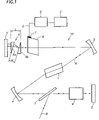
- FIG. 1 is a schematic illustration of a multiple passage laser amplification cavity including the acousto-optical device associated with a train of two correction prisms;
- FIG. 2 is a schematic illustration of a multiple passage laser amplification cavity including the prismatic correction function integrated into the acousto-optical device and into the bottom mirror of said cavity;
- FIG. 3 is a sectional view of a birefringent acousto-optical crystal demonstrating the interaction of optical and acoustic waves;
- FIG. 4 illustrates to within a scaling factor, the curves of the ordinary and extraordinary indices of a uniaxial birefringent acousto-optical crystal, as well as the curve of acoustic slownesses (reciprocal of acoustic velocities) of the acousto-optical crystal;
- FIG. 5 illustrates the curves of the variation of the group delay time versus the wavelength of the light pulse for different dimensional parameters of the train of both prisms.
- the optical signal as ultra-short pulses travels along the path A several times in the laser amplification cavity 10 ; at each passage, the optical signal is amplified in the optical amplifier 1 and is reflected between the bottom mirrors 2 and 3 of said cavity, as well as on the intermediate mirrors 4 and 5 .
- a Pockels cell 6 is centered on the optical path, associated with a polarizer 7 , providing introduction or extraction of the optical signal by switching the polarization of the optical wave.
- An acousto-optical device 8 for example of the type of those which are described in Patent FR No 00 08278 filed in the name of the applicant, which involve at least one birefringent acousto-optical crystal comprising an input face Fe onto which the optical signal is applied and an output Fs from which emerge the diffracted optical signal and the direct optical signal, along a passage direction, and vice versa during the passage in the reverse direction, and at least one transducer T onto which is applied an electrical signal E from a signal generator G controlled by a computer C.
- the direction of propagation of the energy of the acoustic wave may be collinear or quasi-collinear with the direction of propagation of the energy of the optical wave at their interaction area.
- tellurium dioxide provides a relatively high acousto-optical efficiency under the conditions mentioned earlier, notably in the case of a slow shear acoustic wave: this material will therefore be used preferably.
- a train 9 of two prisms 9 a and 9 b is positioned on the path of the optical signal A, between the mirror 3 of said laser amplifier cavity and the acousto-optical device 8 ; said two prisms are positioned so that the apices are inverted relatively to the path A of the optical signal; both faces perpendicular to said path A are separated by a distance of L; both faces oblique to said path A are separated by a distance of d.
- the latter will be amplified by the optical amplifier 1 , filtered by the acousto-optical device 8 and corrected by the train 9 of prisms.
- an electrical signal E may be applied at the transducer D so as to change the shape of the spectrum of the light pulses at the output of the amplifier cavity 10 , via the Pockels cell 6 and the polarizer 7 following the path B.
- Said programming of the electrical signal E applied to the transducer T will be such that the wavelength spectrum of the ultra-short light pulses will comply with the desired template.
- the prismatic function allowing the non-linear dispersions introduced by the acousto-optical crystal to be compensated for, is provided by the train 9 of two prisms 9 a , 9 b.
- the prismatic function may be integrated into the acousto-optical crystal on the one hand, and into the bottom mirror of the laser amplifier cavity on the other hand.
- the prism 9 a is associated with the bottom cavity mirror 3 and the prism 9 b is associated with the acousto-optical crystal 8 ; advantageously, the material making up the prisms 9 a and 9 b is of the same nature as the one making up the acousto-optical crystal 8 .
- the optical beam will be aligned with the Poynting vector of the acoustic beam.
- the programmable acousto-optical device involves an acousto-optical crystal schematically illustrated by a rectangle R and which has, on a small side of said rectangle, an input face Fe, onto which an incident optical beam O i is applied, perpendicularly to said face Fe, polarized perpendicularly to the plane P containing said rectangle R.
- the incident optical beam O i propagates in the acousto-optical crystal and emerges out of an output face Fs, located on the other small side of said rectangle, in two beams, one non-diffracted direct beam O s , perpendicular to the output face Fs, and a diffracted extraordinary beam O d , not perpendicular to the output face Fs.
- the acoustic wave is illustrated by its wave vector K forming an angle ⁇ a with the [110] axis of the crystal and the Poynting vector P a , forming an angle ⁇ a with the [110] axis.
- the incident optical wave O i is directed perpendicularly to the input face Fe of the crystal; its wave vector k o forms an angle ⁇ o with the [110] axis; its polarization is perpendicular to the plane P along the [ 1 10] axis.
- the angle ⁇ o which the wave vector k o forms with the [110] axis will be identical with the ⁇ a which the Poynting vector P a of the acoustic wave forms with the [110] axis.
- the incident optical wave O i will be diffracted according to an extraordinary optical wave O d , the polarization of which is perpendicular to that of the incident optical wave O i , and the wave vector k d forms an angle ⁇ d with the [110] axis.
- the result of the filtering, performed by the acousto-optical crystal is utilized on the non-diffracted direct optical wave O s , with a polarization identical with the one of the incident optical wave O i .
- the crystal illustrated by rectangle R is turned in such a way that the angle ⁇ a which the acoustic wave vector K forms with the [110] axis, lies between 0° and 15°.
- the curves of the C o and C e indices represent the curve of the ordinary index n o and the curve of the extraordinary index n e , respectively.
- the curve of slownesses C L illustrates the variation of the reciprocal of the phase velocity of the shear acoustic wave.
- the crystal is thereby turned in such a way that the Poynting vector of the acoustic wave forms an angle ⁇ a , relatively to the [110] axis, identical with the one which the incident optical wave vector k o forms relatively to the same axis.
- a train 9 of two prisms is positioned according to the invention between said acousto-optical device and the bottom mirror 3 of the laser amplifier cavity 10 .
- the dimensions of parameters L and d respectively define the distance which separates both faces of the prisms, normal to the path of the optical signal A, and the distance which separates both oblique faces of said prisms.
- the L/d ratio varying from 1 to 3 defines a variation of the group time, reduced to the distance d, of +/ ⁇ 0.06.
- Said group time variation is close to zero for a L/d ratio located between 1.8 and 2.
- the non-linear dispersions will be compensated as the group time variation is quasi zero for a given geometry of the train of prisms.
Landscapes
- Physics & Mathematics (AREA)
- Electromagnetism (AREA)
- Engineering & Computer Science (AREA)
- Plasma & Fusion (AREA)
- Optics & Photonics (AREA)
- Lasers (AREA)
- Optical Modulation, Optical Deflection, Nonlinear Optics, Optical Demodulation, Optical Logic Elements (AREA)
- Spectrometry And Color Measurement (AREA)
Applications Claiming Priority (3)
| Application Number | Priority Date | Filing Date | Title |
|---|---|---|---|
| FR03/02667 | 2003-03-03 | ||
| FR0302667A FR2852155B1 (fr) | 2003-03-03 | 2003-03-03 | Procede et dispositif pour le controle de l'amplitude du spectre en longueurs d'ondes des impulsions lumineuses ultra breves emises par les amplificateurs laser a passages multiples |
| PCT/FR2004/000491 WO2004082083A2 (fr) | 2003-03-03 | 2004-03-03 | Procede et dispositif pour le controle de l'amplitude du spectre en longueurs d'ondes des impulsions lumineuses ultra breves emises par les amplificateurs laser a passages multiples. |
Publications (2)
| Publication Number | Publication Date |
|---|---|
| US20060274403A1 US20060274403A1 (en) | 2006-12-07 |
| US7486704B2 true US7486704B2 (en) | 2009-02-03 |
Family
ID=32865241
Family Applications (1)
| Application Number | Title | Priority Date | Filing Date |
|---|---|---|---|
| US10/547,703 Expired - Lifetime US7486704B2 (en) | 2003-03-03 | 2004-03-03 | Method and device for controlling the amplitude of the wavelength spectrum of ultra-short light pulses emitted by multiple passage laser amplifiers |
Country Status (6)
| Country | Link |
|---|---|
| US (1) | US7486704B2 (de) |
| EP (1) | EP1604435B8 (de) |
| AT (1) | ATE449441T1 (de) |
| DE (1) | DE602004024176D1 (de) |
| FR (1) | FR2852155B1 (de) |
| WO (1) | WO2004082083A2 (de) |
Cited By (3)
| Publication number | Priority date | Publication date | Assignee | Title |
|---|---|---|---|---|
| US8207009B2 (en) | 2011-04-19 | 2012-06-26 | Primestar Solar, Inc. | Methods of temporally varying the laser intensity during scribing a photovoltaic device |
| US20120300799A1 (en) * | 2010-02-17 | 2012-11-29 | High Q Laser Gmbh | Laser amplification system and method for generating retrievable laser pulses |
| US8461481B2 (en) | 2011-04-19 | 2013-06-11 | Primestar Solar, Inc. | Methods and apparatus for reducing variations in the laser intensity during scribing a photovoltaic device |
Families Citing this family (24)
| Publication number | Priority date | Publication date | Assignee | Title |
|---|---|---|---|---|
| US7973936B2 (en) | 2001-01-30 | 2011-07-05 | Board Of Trustees Of Michigan State University | Control system and apparatus for use with ultra-fast laser |
| AU2002245345A1 (en) * | 2001-01-30 | 2002-08-12 | Board Of Trustees Operating Michigan State University | Control system and apparatus for use with laser excitation or ionization |
| US7583710B2 (en) | 2001-01-30 | 2009-09-01 | Board Of Trustees Operating Michigan State University | Laser and environmental monitoring system |
| US7450618B2 (en) | 2001-01-30 | 2008-11-11 | Board Of Trustees Operating Michigan State University | Laser system using ultrashort laser pulses |
| US7609731B2 (en) * | 2001-01-30 | 2009-10-27 | Board Of Trustees Operating Michigan State University | Laser system using ultra-short laser pulses |
| US8208505B2 (en) | 2001-01-30 | 2012-06-26 | Board Of Trustees Of Michigan State University | Laser system employing harmonic generation |
| US7567596B2 (en) | 2001-01-30 | 2009-07-28 | Board Of Trustees Of Michigan State University | Control system and apparatus for use with ultra-fast laser |
| EP1851532A1 (de) | 2005-02-14 | 2007-11-07 | Board of Trustees of Michigan State University | Ultraschnelles lasersystem |
| FR2892834B1 (fr) * | 2005-11-03 | 2008-01-25 | Fastlite Sarl | Dispositif de dispersion d'impulsions lumineuses programmable en amplitude spectrale. |
| WO2007064703A2 (en) | 2005-11-30 | 2007-06-07 | Board Of Trustees Of Michigan State University | Laser based identification of molecular characteristics |
| CN100378566C (zh) * | 2006-03-08 | 2008-04-02 | 中国科学院上海光学精密机械研究所 | 宽带高增益再生放大器 |
| US9018562B2 (en) | 2006-04-10 | 2015-04-28 | Board Of Trustees Of Michigan State University | Laser material processing system |
| FR2903819B1 (fr) * | 2006-07-11 | 2008-08-22 | Thales Sa | Dispositif d'etirement et de controle spectral pour lasers impulsionnels a forte puissance crete |
| JP2009032916A (ja) * | 2007-07-27 | 2009-02-12 | Fujifilm Corp | 分散補償器およびそれを用いた固体レーザ装置並びに分散補償方法 |
| EP2232653B1 (de) | 2007-12-21 | 2013-03-27 | Board of Trustees of Michigan State University | Phasensteuerung in ultrakurzpulslasern mit einem verformbaren spiegel im pulsdehner |
| EP2211430A3 (de) | 2009-01-23 | 2015-05-27 | Board of Trustees of Michigan State University | Laserautokorrelationssystem |
| WO2010141128A2 (en) | 2009-03-05 | 2010-12-09 | Board Of Trustees Of Michigan State University | Laser amplification system |
| US8630322B2 (en) | 2010-03-01 | 2014-01-14 | Board Of Trustees Of Michigan State University | Laser system for output manipulation |
| US20120069427A1 (en) * | 2010-09-22 | 2012-03-22 | Fastlite | Method and device for acousto-optic filtering with long optical and acoustic interaction length |
| JP5799538B2 (ja) * | 2011-03-18 | 2015-10-28 | セイコーエプソン株式会社 | テラヘルツ波発生装置、カメラ、イメージング装置、計測装置および光源装置 |
| WO2019012642A1 (ja) * | 2017-07-13 | 2019-01-17 | ギガフォトン株式会社 | レーザシステム |
| CN110673352B (zh) * | 2018-07-02 | 2024-08-30 | 天津大学 | 用于超分辨率成像的太赫兹结构光调制装置 |
| CN110768092B (zh) * | 2019-10-28 | 2020-10-30 | 华中科技大学 | 一种基于声光效应的激光再生放大器 |
| RU2751446C1 (ru) * | 2020-12-29 | 2021-07-13 | Федеральное государственное автономное образовательное учреждение высшего образования "Национальный исследовательский технологический университет "МИСиС" | Способ компенсации сужения спектра излучения в лазерном регенеративном усилителе и устройство для его осуществления |
Citations (12)
| Publication number | Priority date | Publication date | Assignee | Title |
|---|---|---|---|---|
| US3644015A (en) | 1970-06-18 | 1972-02-22 | Hewlett Packard Co | Acousto-optic band reject light filter and apparatus using same |
| US3817598A (en) * | 1972-09-25 | 1974-06-18 | Us Navy | Laser beam deflection system |
| US3951509A (en) * | 1973-04-17 | 1976-04-20 | Fuji Photo Film Co., Ltd. | Apparatus for deflecting light and scanning line conversion system |
| US4017807A (en) | 1976-02-23 | 1977-04-12 | The United States Of America As Represented By The Secretary Of The Navy | Electronically controlled digital laser |
| US4622845A (en) * | 1985-03-21 | 1986-11-18 | Westinghouse Electric Corp. | Method and apparatus for the detection and measurement of gases |
| US4685772A (en) | 1982-12-23 | 1987-08-11 | The United States Of America As Represented By The Secretary Of The Air Force | Tunable acousto-optic filter with improved spectral resolution and increased aperture |
| US5189676A (en) * | 1989-09-06 | 1993-02-23 | The Board Of Trustees Of The Leland Stanford Junior University | Broadband laser source |
| FR2684194A1 (fr) | 1991-11-22 | 1993-05-28 | Sapriel Jacques | Dispositif acousto-optique utilisant un materiau, notamment un materiau semi-conducteur, au voisinage de son seuil d'absorption optique. |
| FR2751094A1 (fr) | 1996-07-09 | 1998-01-16 | Thomson Csf | Dispositif de controle d'impulsions lumineuses par un dispositif programmable acousto-optique |
| US6072813A (en) | 1996-07-09 | 2000-06-06 | Thomson-Csf | Device for controlling light pulses by a programmable acoustooptic device |
| FR2810750A1 (fr) | 2000-06-21 | 2001-12-28 | Fastlite | Dispositif acousto-optique programmable pour le controle de l'amplitude du spectre en longueurs d'onde des systemes de communications optiques multiplexes en longueurs d'onde |
| FR2820837A1 (fr) | 2001-02-12 | 2002-08-16 | Fastlite | Perfectionnement aux dispositif acousto-optiques programmables pour systemes de communication optiques |
-
2003
- 2003-03-03 FR FR0302667A patent/FR2852155B1/fr not_active Expired - Fee Related
-
2004
- 2004-03-03 DE DE602004024176T patent/DE602004024176D1/de not_active Expired - Lifetime
- 2004-03-03 EP EP04716625A patent/EP1604435B8/de not_active Expired - Lifetime
- 2004-03-03 US US10/547,703 patent/US7486704B2/en not_active Expired - Lifetime
- 2004-03-03 WO PCT/FR2004/000491 patent/WO2004082083A2/fr not_active Ceased
- 2004-03-03 AT AT04716625T patent/ATE449441T1/de active
Patent Citations (13)
| Publication number | Priority date | Publication date | Assignee | Title |
|---|---|---|---|---|
| US3644015A (en) | 1970-06-18 | 1972-02-22 | Hewlett Packard Co | Acousto-optic band reject light filter and apparatus using same |
| US3817598A (en) * | 1972-09-25 | 1974-06-18 | Us Navy | Laser beam deflection system |
| US3951509A (en) * | 1973-04-17 | 1976-04-20 | Fuji Photo Film Co., Ltd. | Apparatus for deflecting light and scanning line conversion system |
| US4017807A (en) | 1976-02-23 | 1977-04-12 | The United States Of America As Represented By The Secretary Of The Navy | Electronically controlled digital laser |
| US4685772A (en) | 1982-12-23 | 1987-08-11 | The United States Of America As Represented By The Secretary Of The Air Force | Tunable acousto-optic filter with improved spectral resolution and increased aperture |
| US4622845A (en) * | 1985-03-21 | 1986-11-18 | Westinghouse Electric Corp. | Method and apparatus for the detection and measurement of gases |
| US5189676A (en) * | 1989-09-06 | 1993-02-23 | The Board Of Trustees Of The Leland Stanford Junior University | Broadband laser source |
| FR2684194A1 (fr) | 1991-11-22 | 1993-05-28 | Sapriel Jacques | Dispositif acousto-optique utilisant un materiau, notamment un materiau semi-conducteur, au voisinage de son seuil d'absorption optique. |
| FR2751094A1 (fr) | 1996-07-09 | 1998-01-16 | Thomson Csf | Dispositif de controle d'impulsions lumineuses par un dispositif programmable acousto-optique |
| US6072813A (en) | 1996-07-09 | 2000-06-06 | Thomson-Csf | Device for controlling light pulses by a programmable acoustooptic device |
| FR2810750A1 (fr) | 2000-06-21 | 2001-12-28 | Fastlite | Dispositif acousto-optique programmable pour le controle de l'amplitude du spectre en longueurs d'onde des systemes de communications optiques multiplexes en longueurs d'onde |
| US20040012837A1 (en) | 2000-06-21 | 2004-01-22 | Daniel Kaplan | Programmable acousto-optic device |
| FR2820837A1 (fr) | 2001-02-12 | 2002-08-16 | Fastlite | Perfectionnement aux dispositif acousto-optiques programmables pour systemes de communication optiques |
Non-Patent Citations (7)
Cited By (4)
| Publication number | Priority date | Publication date | Assignee | Title |
|---|---|---|---|---|
| US20120300799A1 (en) * | 2010-02-17 | 2012-11-29 | High Q Laser Gmbh | Laser amplification system and method for generating retrievable laser pulses |
| US8582614B2 (en) * | 2010-02-17 | 2013-11-12 | High Q Laser Gmbh | Laser amplification system and method for generating retrievable laser pulses |
| US8207009B2 (en) | 2011-04-19 | 2012-06-26 | Primestar Solar, Inc. | Methods of temporally varying the laser intensity during scribing a photovoltaic device |
| US8461481B2 (en) | 2011-04-19 | 2013-06-11 | Primestar Solar, Inc. | Methods and apparatus for reducing variations in the laser intensity during scribing a photovoltaic device |
Also Published As
| Publication number | Publication date |
|---|---|
| FR2852155A1 (fr) | 2004-09-10 |
| EP1604435B1 (de) | 2009-11-18 |
| EP1604435A2 (de) | 2005-12-14 |
| WO2004082083A2 (fr) | 2004-09-23 |
| FR2852155B1 (fr) | 2006-08-25 |
| US20060274403A1 (en) | 2006-12-07 |
| ATE449441T1 (de) | 2009-12-15 |
| DE602004024176D1 (de) | 2009-12-31 |
| EP1604435B8 (de) | 2010-02-17 |
| WO2004082083A3 (fr) | 2005-03-24 |
Similar Documents
| Publication | Publication Date | Title |
|---|---|---|
| US20060274403A1 (en) | Method and device for controlling the amplitude of the wavelength spectrum of ultra-short light pulses emitted by multiple passage laser amplifiers | |
| US7630418B2 (en) | Laser system for generation of high-power sub-nanosecond pulses with controllable wavelength in 2-15 μm region | |
| US5572358A (en) | Regenerative amplifier incorporating a spectral filter within the resonant cavity | |
| US5592327A (en) | Regenerative amplifier incorporating a spectral filter within the resonant cavity | |
| US8049956B2 (en) | Apparatus for spectrum-doubled optical parametric chirped pulse amplification (OPCPA) using third-order dispersion chirping | |
| DE69331453T2 (de) | Vorrichtung zur Erzeugung von Laserstrahlen | |
| US5835512A (en) | Wavelength selecting method in wavelength tunable laser and wavelength selectable laser oscillator in wavelength tunable laser | |
| JP5376652B2 (ja) | レーザー装置及びレーザー増幅方法 | |
| US6870664B2 (en) | Nondegenerate optical parametric chirped pulse amplifier | |
| CN103311791B (zh) | 飞秒光学参量放大器 | |
| US20040012837A1 (en) | Programmable acousto-optic device | |
| US9448363B2 (en) | Device for compensation of time dispersion applied to the generation of ultrashort light pulses | |
| WO2025173653A1 (ja) | 波長変換機構および波長変換方法 | |
| JP2005208472A (ja) | コヒーレント光源 | |
| CN115113408A (zh) | 一种啁啾脉冲展宽压缩装置及放大系统 | |
| EP2051137A1 (de) | Lasersystem und Verfahren zur Erzeugung und Verstärkung optischer Impulse mit einer abstimmbaren Ausgangswellenlänge zwischen ca. 0,75 und 2,5 m | |
| JP7794586B2 (ja) | レーザ増幅装置及びレーザ増幅方法 | |
| CN1123102C (zh) | 同步输出十太瓦级不同脉宽的双脉冲激光装置 | |
| CN111146670A (zh) | 一种紫外脉冲激光器 | |
| JP5388224B2 (ja) | コヒーレント光源 | |
| RU2453878C1 (ru) | Акустооптическая дисперсионная линия задержки | |
| WO2025173654A1 (ja) | 波長変換機構および波長変換方法 | |
| JP2025125009A (ja) | 波長変換装置および波長変換方法 | |
| EP2431791B1 (de) | Verfahren und Vorrichtung zur akusto-optischen Filterung mit großer akusto-optischer Interaktionslänge | |
| Bournet et al. | On the efficiency of Intrapulse Difference Frequency Generation MIR systems |
Legal Events
| Date | Code | Title | Description |
|---|---|---|---|
| AS | Assignment |
Owner name: FASTLITE, FRANCE Free format text: ASSIGNMENT OF ASSIGNORS INTEREST;ASSIGNORS:KAPLAN, DANIEL;OKSENHENDLER, THOMAS;TOURNOIS, PIERRE;REEL/FRAME:018238/0740 Effective date: 20060701 |
|
| STCF | Information on status: patent grant |
Free format text: PATENTED CASE |
|
| FPAY | Fee payment |
Year of fee payment: 4 |
|
| FPAY | Fee payment |
Year of fee payment: 8 |
|
| MAFP | Maintenance fee payment |
Free format text: PAYMENT OF MAINTENANCE FEE, 12TH YR, SMALL ENTITY (ORIGINAL EVENT CODE: M2553); ENTITY STATUS OF PATENT OWNER: SMALL ENTITY Year of fee payment: 12 |