US748480A - Lubricator. - Google Patents
Lubricator. Download PDFInfo
- Publication number
- US748480A US748480A US15236703A US1903152367A US748480A US 748480 A US748480 A US 748480A US 15236703 A US15236703 A US 15236703A US 1903152367 A US1903152367 A US 1903152367A US 748480 A US748480 A US 748480A
- Authority
- US
- United States
- Prior art keywords
- journal
- lubricator
- spreader
- shaft
- plates
- Prior art date
- Legal status (The legal status is an assumption and is not a legal conclusion. Google has not performed a legal analysis and makes no representation as to the accuracy of the status listed.)
- Expired - Lifetime
Links
Images

Classifications
-
- B—PERFORMING OPERATIONS; TRANSPORTING
- B61—RAILWAYS
- B61F—RAIL VEHICLE SUSPENSIONS, e.g. UNDERFRAMES, BOGIES OR ARRANGEMENTS OF WHEEL AXLES; RAIL VEHICLES FOR USE ON TRACKS OF DIFFERENT WIDTH; PREVENTING DERAILING OF RAIL VEHICLES; WHEEL GUARDS, OBSTRUCTION REMOVERS OR THE LIKE FOR RAIL VEHICLES
- B61F17/00—Lubrication specially adapted for axle-boxes of rail vehicles
- B61F17/02—Lubrication specially adapted for axle-boxes of rail vehicles with oil
- B61F17/14—Rotating lubricating devices
- B61F17/22—Rotating lubricating devices with discs, rollers, or belts engaging the axle
Definitions
- My invention relates to improvements in that type of car-axle or other bearinglnbricator mechanisms in which the lubricant is fed to the journal by roller conveyors held in contact with the journal under the action of spring-pressed means; and my invention primarily seeks to provide an improved lubricator of the type referred to in which the several cooperative parts thereof are compactly arranged, capable of being economically constructed and readily assembled, and which effectively serve for their intended purposes.
- my invention comprehends an improved means for conveying the lubricant to the journal in a uniform manner, a spreading device which automatically adjusts itself to allow for feeding a thin layer of oil over the journal and in which the oil conveying or take-up devices are designed to also provide for lubricating the actuating parts forming the complete lubricator.
- my invention includes a peculiar construction of oilspreader devices combined with ameans for carrying the oil thereto and adapted to maintain the entire lubricator parts in a proper radial line with respect to the journal and for uniformly holding the oil-carryin g devices in contact with the said journal.
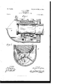
- My invention also embodies a simple and efiective springsupporting means for sustaining the lubricant feed and spreader devices in a proper operative condition when used either within a round or a flat bottom journal-box and having suflicient tension for causing the spreader devices to automatically adjust themselves to take up the wear thereon caused by long and continued use of the complete lubricator, and, finally, my invention consists in certain details of construction and peculiar combination of parts, all of which will hereinafter be fully described, and specifically pointed out in the appended claims, reference'being had to the drawings, in which- Figure 1 is. a longitudinal section of a caraxle box, showing my construction of lubricator devices applied for use. Fig.
- Fig. 2 is a transverse sectionof the same, taken practically on the line 2 2 of Fig. 1 looking in the direction of the arrow, the dotted lines indieating-the relative length of the spring parts used in a fiat-bottom journal-box.
- Fig. 3 is an inverted plan View of the lubricator devices.
- Fig. 4 is a detail view of a slightlymodified form of my lubricator, the parts being shown in use as single ring oiler for short journals.
- Figji is a detail view of several of the combined spreader and seat plates shown in Figs. 1 and 2.
- Fig. 6 is a cross-section taken on the line 6 6 of Fig. 4.
- Fig. 7 is a transverse section of a slightly-modified arrangement of my invention.
- a roller 6 Near each end of the axle 9 is loosely mounted a roller 6, and upon each of the rollers 6 is loosely held to rotate thereon a ring 5, which is preferably of hard metal, but may be formed of some suitable flexible material, such as leather, hard metal being preferred on account of its durability.
- the rings 5 act as oil-carriers, and they are held in frictional contact with the journal A.
- 11 11 represent the oil-spreader devices, each of which comprises a longitudinally-extended plate 11, curved in such manner that the outer edge only thereof bears against the journal, as clearly shown in Fig. 2, and the said plates 11 have inwardly-projecting arms 7 7 formed integrally therewith, the ends of which are cut out, as. at 7, whereby to extend over but not encircle the shaft 9, and the plates 11 are also formed with integrally inwardly projecting arms 8 8, the ends of which are apertured, whereby to fit around the shaft to form bearings thereon for the plates 11
- the arms 1 1 are provided to hold the opposite spreader-plates 11* in contact with the under side of the journal (see Fig. 2) under sufficient pressure whereby to automatically adjust the said spreader-plates to take up wear, and the said spring-brackets maintain the shaft under asufficient upward pressure to hold the spring under the desired pressure against the plates 11 and at the same time hold the lubricant-conveying rings 5 in a proper frictional contact with the journal A.
- brackets 4 are curved upwardly to form smooth bearings to engage the bottom of the axle-boxes, and the length of the bearing ends of the said brackets is such as to properly engage with a round bottom journal-box, as shown in Fig. 2, or with a fiat journal-box bottom in a manner clearly understood by referring to Fig. 7.
- the oil-spreaders 11 11 have a series of narrow ribs 3 on their upper or journal-engaging edges whereby to hold the said edges off from the journal-periphery a distance only sufficient to permit a thin layer or film of oil to pass between the said spreader edges to distribute over or adhere to the journal-faces.
- the spreader devices By arranging the spreader devices as shown and described they not alone serve to distribute the oil in a uniform thin layer onto the journal, but they also serve as a means for balancing the whole device in a proper radial adjustment with the journal.
- Figs. 4 and 6 is illustrated a modified form of my invention, in which the parts are especially constructed for application to a short journal, and in this latter form the spring-brackets or supporting portions 4 and 1 are disposed outside of the arms 8 8 and joined with the shaft 9 by single or double turn coils, and a single ring 5 is mounted on the shaft 9 between the members 8 8, the spreader-plate 11 being constructed similar to that shown in the other construction, before described, and illustrated in Figs. 1, 2, and 3.
Description
PATENTED DEC. 29, 1903.
A. E. CLIFTON. LUBRIGATOR. APPLICATION FILEDAPR. 1a, 1903.
2 SHEETS-SHEET 1.
' no MODEL.
' WITNESSES:
' INVENTOH ire/ e71? C Zz ion.
iJ/M No. 748,480. PATENTED DEC. 29, 1903 A. EZGLIFTON.
LUBRIGATUR.
APPLICATION FILED APR. 13. 1903.
N0 MODEL. 2 SHEETS-SHEET 2- WITNESSES:
INVENTO/i Jr's/lei [,Uion.
UNIT D STATES Iatented becemloer Q9, 1903.
PATENT OFFICE.
ARCHER. EVANS CLIFTON, OF PITTSBURG, PENNSYLVANIA, ASSIGNOR OF ONE-HALF TO GEORGE H. TRUMP, OF PITTSBURG, PENNSYLVANIA.
LUBRICATOR.
SPECIFICATION forming part of Letters Patent N 0. 748,480, dated December 29, 1903.
Application filed April 18, 1903. Serial No- 152 36'7. (No model.)
To aZZ whom it may concern:
Be it known that I, ARCHER EVANS CLIF- TON, residing at Pittsburg, inthe county of Allegheny and State of Pennsylvania, have invented a new and Improved Lubricator, of which the following is a specification.
My invention relates to improvements in that type of car-axle or other bearinglnbricator mechanisms in which the lubricant is fed to the journal by roller conveyors held in contact with the journal under the action of spring-pressed means; and my invention primarily seeks to provide an improved lubricator of the type referred to in which the several cooperative parts thereof are compactly arranged, capable of being economically constructed and readily assembled, and which effectively serve for their intended purposes.
In its generic nature my invention comprehends an improved means for conveying the lubricant to the journal in a uniform manner, a spreading device which automatically adjusts itself to allow for feeding a thin layer of oil over the journal and in which the oil conveying or take-up devices are designed to also provide for lubricating the actuating parts forming the complete lubricator.
In its more complete nature my invention includes a peculiar construction of oilspreader devices combined with ameans for carrying the oil thereto and adapted to maintain the entire lubricator parts in a proper radial line with respect to the journal and for uniformly holding the oil-carryin g devices in contact with the said journal. My invention also embodies a simple and efiective springsupporting means for sustaining the lubricant feed and spreader devices in a proper operative condition when used either within a round or a flat bottom journal-box and having suflicient tension for causing the spreader devices to automatically adjust themselves to take up the wear thereon caused by long and continued use of the complete lubricator, and, finally, my invention consists in certain details of construction and peculiar combination of parts, all of which will hereinafter be fully described, and specifically pointed out in the appended claims, reference'being had to the drawings, in which- Figure 1 is. a longitudinal section of a caraxle box, showing my construction of lubricator devices applied for use. Fig. 2 is a transverse sectionof the same, taken practically on the line 2 2 of Fig. 1 looking in the direction of the arrow, the dotted lines indieating-the relative length of the spring parts used in a fiat-bottom journal-box. Fig. 3 is an inverted plan View of the lubricator devices. Fig. 4 is a detail view of a slightlymodified form of my lubricator, the parts being shown in use as single ring oiler for short journals. Figji is a detail view of several of the combined spreader and seat plates shown in Figs. 1 and 2. Fig. 6 is a cross-section taken on the line 6 6 of Fig. 4. Fig. 7 is a transverse section of a slightly-modified arrangement of my invention.
In the practical application of my invention the same embodies a short shaft 9, of
steel or other hard wearing metal, which extends in the longitudinal plane of the axlejournal A, mounted in the journal-box Bin the usual manner.
Near each end of the axle 9 is loosely mounted a roller 6, and upon each of the rollers 6 is loosely held to rotate thereon a ring 5, which is preferably of hard metal, but may be formed of some suitable flexible material, such as leather, hard metal being preferred on account of its durability.
The rings 5 act as oil-carriers, and they are held in frictional contact with the journal A.
11 11 represent the oil-spreader devices, each of which comprises a longitudinally-extended plate 11, curved in such manner that the outer edge only thereof bears against the journal, as clearly shown in Fig. 2, and the said plates 11 have inwardly-projecting arms 7 7 formed integrally therewith, the ends of which are cut out, as. at 7, whereby to extend over but not encircle the shaft 9, and the plates 11 are also formed with integrally inwardly projecting arms 8 8, the ends of which are apertured, whereby to fit around the shaft to form bearings thereon for the plates 11 The shaft 9, which forms the main support for the operating parts. when the lubricator devices are arranged as shown in Figs. 1 and 2, is sustained upon U-shaped brackets 4 4,
formed of stout spring-rods, the cross members of which are in the nature of springcoils 4. The coil portions 4 of the said two brackets are intertwisted upon the shaft 9, as clearly shown in Fig. 3, by reference to which it will also be noticedthe coils 4 have their ends disposed adjacent a supplemental set of spring arms or brackets 1 1, having coils that encircle the shaft 9 and having their spread ends projected upwardly in engagement with the apertured ears 2 on the under side of the combined seat and spreader plates 11.
The arms 1 1 are provided to hold the opposite spreader-plates 11* in contact with the under side of the journal (see Fig. 2) under sufficient pressure whereby to automatically adjust the said spreader-plates to take up wear, and the said spring-brackets maintain the shaft under asufficient upward pressure to hold the spring under the desired pressure against the plates 11 and at the same time hold the lubricant-conveying rings 5 in a proper frictional contact with the journal A.
The extremities of the brackets 4; are curved upwardly to form smooth bearings to engage the bottom of the axle-boxes, and the length of the bearing ends of the said brackets is such as to properly engage with a round bottom journal-box, as shown in Fig. 2, or with a fiat journal-box bottom in a manner clearly understood by referring to Fig. 7.
The oil-spreaders 11 11 have a series of narrow ribs 3 on their upper or journal-engaging edges whereby to hold the said edges off from the journal-periphery a distance only sufficient to permit a thin layer or film of oil to pass between the said spreader edges to distribute over or adhere to the journal-faces.
By arranging the spreader devices as shown and described they not alone serve to distribute the oil in a uniform thin layer onto the journal, but they also serve as a means for balancing the whole device in a proper radial adjustment with the journal.
It will be apparent that by reason of the rings 5 5 being held in a spring-pressed frictional engagement with the journal the said rings will be caused to turn on their bearingroll'ers 6 6,and the latter will in turn be caused to rotate upon the shaft 9, and by reason of the free revolution of the rings 5 around the r0llers'6 and that of the rollers 6 around the shaft 9 the several parts will be self-oiling, as the oil which adheres to the inside of the rings 5, the lower portions of which are immersed in the lubricant, (see Fig. 2,) is distributed to the roller 6 and the shaft 9, while the oil carried upon the external face of rings 5 is taken up by the journal.
In Figs. 4 and 6 is illustrated a modified form of my invention, in which the parts are especially constructed for application to a short journal, and in this latter form the spring-brackets or supporting portions 4 and 1 are disposed outside of the arms 8 8 and joined with the shaft 9 by single or double turn coils, and a single ring 5 is mounted on the shaft 9 between the members 8 8, the spreader-plate 11 being constructed similar to that shown in the other construction, before described, and illustrated in Figs. 1, 2, and 3.
By placing a single ring 5 between the spreader-arms 8 in the manner shown sufficient oil will be carried up thereby to the spreaders for efiectively lubricating a short journal.
From the foregoing description, taken in connection with the accompanying drawings, the complete operations and advantages of my invention will be readily apparent to those skilled in the art to which it appertains.
While the details of construction shown present a preferred arrangement of my invention, it is manifest the same may be modified or varied without departing from the spirit of my invention or the scope of the appended claims.
Having thus described my invention, what I claim, and desire to secure by Letters Patent, is-- 1. The combination in a lubricator for car or other axle bearings, with a journal, and an oil-reservoir under the journal; of a support under the journal extended in the longitudinal plane thereof, said support including expansible spring-legs for resting on the bottom of the oil-reservoir, spreader-plates projected in the longitudinal direction of the journal for engaging the opposite sides of the under side of the said journal, spring-brackets for sustaining the uppermost edges only of the spreaders in contact with the journal, said spring-brackets being mounted on the spring-pressed support under the journal, for the purposes set forth.
2. 'In a lubricator for the purposes described; the combination with the journalbox and the journal; of a shaft mounted lengthwise of the journal-box under the journal, spring-rod brackets sustained on the bottom of the box and having bearings for the supporting-shaft, spring-rod brackets mounted on each end of the shaft including upwardly-diverging ends which project laterally under the journal, spreader-plates supported on the extremities of the said diverging ends, one at each side of the journal, said spreader-plates being transversely curved and held so their upper edges only engage the journal,substantially as shown and described.
3. The combination in a lubricator, of a box, a journal, plates extended lengthwise of the journal, one at each side thereof, said plates being curved transversely and having ribs on the inner face of their outer edges, a ring frictionally engaging the under side of the journal, a means mounted on the bottom of the box for holding the ring in frictional contact with the journal, said means including a longitudinally-extended shaft located tact with the under side of the journal, a spreader-plate on each side of the lower face of the journal extended lengthwise thereof, said plates having inwardly-extended brackets mounted on the supporting-shaft with their extremities spread laterally in opposite directions under the journal, and connected to the spreader-plates to press them against the journal, substantially as shown and for the purposes described.
ARCHER EVANS CLIFTON. Witnesses:
D. B. OAKS, S. W. CANNER.
Priority Applications (1)
| Application Number | Priority Date | Filing Date | Title |
|---|---|---|---|
| US15236703A US748480A (en) | 1903-04-13 | 1903-04-13 | Lubricator. |
Applications Claiming Priority (1)
| Application Number | Priority Date | Filing Date | Title |
|---|---|---|---|
| US15236703A US748480A (en) | 1903-04-13 | 1903-04-13 | Lubricator. |
Publications (1)
| Publication Number | Publication Date |
|---|---|
| US748480A true US748480A (en) | 1903-12-29 |
Family
ID=2816974
Family Applications (1)
| Application Number | Title | Priority Date | Filing Date |
|---|---|---|---|
| US15236703A Expired - Lifetime US748480A (en) | 1903-04-13 | 1903-04-13 | Lubricator. |
Country Status (1)
| Country | Link |
|---|---|
| US (1) | US748480A (en) |
Cited By (1)
| Publication number | Priority date | Publication date | Assignee | Title |
|---|---|---|---|---|
| US2668741A (en) * | 1952-01-23 | 1954-02-09 | Harley T Rockwell | Journal lubricator |
-
1903
- 1903-04-13 US US15236703A patent/US748480A/en not_active Expired - Lifetime
Cited By (1)
| Publication number | Priority date | Publication date | Assignee | Title |
|---|---|---|---|---|
| US2668741A (en) * | 1952-01-23 | 1954-02-09 | Harley T Rockwell | Journal lubricator |
Similar Documents
| Publication | Publication Date | Title |
|---|---|---|
| US748480A (en) | Lubricator. | |
| US591406A (en) | Self-oiling device for journals | |
| US332646A (en) | Car-axle box | |
| US2476618A (en) | Waste guard | |
| US260955A (en) | William don | |
| US496325A (en) | Axle-lubricator | |
| US642134A (en) | Automatic journal-oiler. | |
| US371258A (en) | Cae axle lubricator | |
| US273991A (en) | holmes | |
| US732318A (en) | Journal-lubricator. | |
| US1481544A (en) | Lubricator | |
| US1068199A (en) | Lubricator. | |
| US310755A (en) | Car-axle lubricator | |
| US337779A (en) | Car-axle lubricator | |
| US1404651A (en) | Free-oil journal lubrication | |
| US1432496A (en) | Lubricating device | |
| US663407A (en) | Oiler for car-journals. | |
| US322278A (en) | Car-axle lubricator | |
| US769130A (en) | Journal-box. | |
| US293706A (en) | Addison beadfobd | |
| US205768A (en) | Improvement in car-axle boxes | |
| US434983A (en) | Journal-lubricating device | |
| US416535A (en) | Car-axle lubricator | |
| US686715A (en) | Dust-guard for car-axle boxes. | |
| US641866A (en) | Automatic journal-oiler for locomotive-axle journals. |